EP1081370A2 - Intake and exhaust control systems for engine - Google Patents
Intake and exhaust control systems for engine Download PDFInfo
- Publication number
- EP1081370A2 EP1081370A2 EP00117434A EP00117434A EP1081370A2 EP 1081370 A2 EP1081370 A2 EP 1081370A2 EP 00117434 A EP00117434 A EP 00117434A EP 00117434 A EP00117434 A EP 00117434A EP 1081370 A2 EP1081370 A2 EP 1081370A2
- Authority
- EP
- European Patent Office
- Prior art keywords
- exhaust
- valve
- intake
- engine
- pipe
- Prior art date
- Legal status (The legal status is an assumption and is not a legal conclusion. Google has not performed a legal analysis and makes no representation as to the accuracy of the status listed.)
- Granted
Links
- 239000007789 gas Substances 0.000 claims description 48
- 238000004891 communication Methods 0.000 claims description 44
- 230000000903 blocking effect Effects 0.000 claims description 3
- 230000005540 biological transmission Effects 0.000 abstract description 23
- 238000009413 insulation Methods 0.000 description 19
- 230000000694 effects Effects 0.000 description 18
- 239000003054 catalyst Substances 0.000 description 10
- 230000002093 peripheral effect Effects 0.000 description 8
- 230000010349 pulsation Effects 0.000 description 8
- 238000011144 upstream manufacturing Methods 0.000 description 8
- OKTJSMMVPCPJKN-UHFFFAOYSA-N Carbon Chemical compound [C] OKTJSMMVPCPJKN-UHFFFAOYSA-N 0.000 description 4
- 238000006243 chemical reaction Methods 0.000 description 4
- 239000000446 fuel Substances 0.000 description 4
- 238000005192 partition Methods 0.000 description 4
- 238000007789 sealing Methods 0.000 description 4
- 229910000831 Steel Inorganic materials 0.000 description 3
- 230000004913 activation Effects 0.000 description 3
- 239000011491 glass wool Substances 0.000 description 3
- 230000000717 retained effect Effects 0.000 description 3
- 239000010959 steel Substances 0.000 description 3
- 210000002268 wool Anatomy 0.000 description 3
- 229910052799 carbon Inorganic materials 0.000 description 2
- 230000003197 catalytic effect Effects 0.000 description 2
- 239000002828 fuel tank Substances 0.000 description 2
- 229910002804 graphite Inorganic materials 0.000 description 2
- 239000010439 graphite Substances 0.000 description 2
- 239000000463 material Substances 0.000 description 2
- 239000000203 mixture Substances 0.000 description 2
- 229910052755 nonmetal Inorganic materials 0.000 description 2
- 238000013021 overheating Methods 0.000 description 2
- 238000000638 solvent extraction Methods 0.000 description 2
- 238000003466 welding Methods 0.000 description 2
- 230000002411 adverse Effects 0.000 description 1
- 230000015572 biosynthetic process Effects 0.000 description 1
- 230000006835 compression Effects 0.000 description 1
- 238000007906 compression Methods 0.000 description 1
- 230000006866 deterioration Effects 0.000 description 1
- 230000008030 elimination Effects 0.000 description 1
- 238000003379 elimination reaction Methods 0.000 description 1
- 238000002347 injection Methods 0.000 description 1
- 239000007924 injection Substances 0.000 description 1
- 238000004804 winding Methods 0.000 description 1
Images







Classifications
-
- F—MECHANICAL ENGINEERING; LIGHTING; HEATING; WEAPONS; BLASTING
- F02—COMBUSTION ENGINES; HOT-GAS OR COMBUSTION-PRODUCT ENGINE PLANTS
- F02M—SUPPLYING COMBUSTION ENGINES IN GENERAL WITH COMBUSTIBLE MIXTURES OR CONSTITUENTS THEREOF
- F02M35/00—Combustion-air cleaners, air intakes, intake silencers, or induction systems specially adapted for, or arranged on, internal-combustion engines
- F02M35/10—Air intakes; Induction systems
- F02M35/10006—Air intakes; Induction systems characterised by the position of elements of the air intake system in direction of the air intake flow, i.e. between ambient air inlet and supply to the combustion chamber
- F02M35/10013—Means upstream of the air filter; Connection to the ambient air
-
- F—MECHANICAL ENGINEERING; LIGHTING; HEATING; WEAPONS; BLASTING
- F02—COMBUSTION ENGINES; HOT-GAS OR COMBUSTION-PRODUCT ENGINE PLANTS
- F02B—INTERNAL-COMBUSTION PISTON ENGINES; COMBUSTION ENGINES IN GENERAL
- F02B27/00—Use of kinetic or wave energy of charge in induction systems, or of combustion residues in exhaust systems, for improving quantity of charge or for increasing removal of combustion residues
- F02B27/02—Use of kinetic or wave energy of charge in induction systems, or of combustion residues in exhaust systems, for improving quantity of charge or for increasing removal of combustion residues the systems having variable, i.e. adjustable, cross-sectional areas, chambers of variable volume, or like variable means
-
- F—MECHANICAL ENGINEERING; LIGHTING; HEATING; WEAPONS; BLASTING
- F02—COMBUSTION ENGINES; HOT-GAS OR COMBUSTION-PRODUCT ENGINE PLANTS
- F02B—INTERNAL-COMBUSTION PISTON ENGINES; COMBUSTION ENGINES IN GENERAL
- F02B27/00—Use of kinetic or wave energy of charge in induction systems, or of combustion residues in exhaust systems, for improving quantity of charge or for increasing removal of combustion residues
- F02B27/02—Use of kinetic or wave energy of charge in induction systems, or of combustion residues in exhaust systems, for improving quantity of charge or for increasing removal of combustion residues the systems having variable, i.e. adjustable, cross-sectional areas, chambers of variable volume, or like variable means
- F02B27/0205—Use of kinetic or wave energy of charge in induction systems, or of combustion residues in exhaust systems, for improving quantity of charge or for increasing removal of combustion residues the systems having variable, i.e. adjustable, cross-sectional areas, chambers of variable volume, or like variable means characterised by the charging effect
- F02B27/0215—Oscillating pipe charging, i.e. variable intake pipe length charging
-
- F—MECHANICAL ENGINEERING; LIGHTING; HEATING; WEAPONS; BLASTING
- F02—COMBUSTION ENGINES; HOT-GAS OR COMBUSTION-PRODUCT ENGINE PLANTS
- F02B—INTERNAL-COMBUSTION PISTON ENGINES; COMBUSTION ENGINES IN GENERAL
- F02B27/00—Use of kinetic or wave energy of charge in induction systems, or of combustion residues in exhaust systems, for improving quantity of charge or for increasing removal of combustion residues
- F02B27/02—Use of kinetic or wave energy of charge in induction systems, or of combustion residues in exhaust systems, for improving quantity of charge or for increasing removal of combustion residues the systems having variable, i.e. adjustable, cross-sectional areas, chambers of variable volume, or like variable means
- F02B27/0226—Use of kinetic or wave energy of charge in induction systems, or of combustion residues in exhaust systems, for improving quantity of charge or for increasing removal of combustion residues the systems having variable, i.e. adjustable, cross-sectional areas, chambers of variable volume, or like variable means characterised by the means generating the charging effect
- F02B27/0268—Valves
- F02B27/0273—Flap valves
-
- F—MECHANICAL ENGINEERING; LIGHTING; HEATING; WEAPONS; BLASTING
- F02—COMBUSTION ENGINES; HOT-GAS OR COMBUSTION-PRODUCT ENGINE PLANTS
- F02B—INTERNAL-COMBUSTION PISTON ENGINES; COMBUSTION ENGINES IN GENERAL
- F02B27/00—Use of kinetic or wave energy of charge in induction systems, or of combustion residues in exhaust systems, for improving quantity of charge or for increasing removal of combustion residues
- F02B27/02—Use of kinetic or wave energy of charge in induction systems, or of combustion residues in exhaust systems, for improving quantity of charge or for increasing removal of combustion residues the systems having variable, i.e. adjustable, cross-sectional areas, chambers of variable volume, or like variable means
- F02B27/0294—Actuators or controllers therefor; Diagnosis; Calibration
-
- F—MECHANICAL ENGINEERING; LIGHTING; HEATING; WEAPONS; BLASTING
- F02—COMBUSTION ENGINES; HOT-GAS OR COMBUSTION-PRODUCT ENGINE PLANTS
- F02B—INTERNAL-COMBUSTION PISTON ENGINES; COMBUSTION ENGINES IN GENERAL
- F02B27/00—Use of kinetic or wave energy of charge in induction systems, or of combustion residues in exhaust systems, for improving quantity of charge or for increasing removal of combustion residues
- F02B27/04—Use of kinetic or wave energy of charge in induction systems, or of combustion residues in exhaust systems, for improving quantity of charge or for increasing removal of combustion residues in exhaust systems only, e.g. for sucking-off combustion gases
- F02B27/06—Use of kinetic or wave energy of charge in induction systems, or of combustion residues in exhaust systems, for improving quantity of charge or for increasing removal of combustion residues in exhaust systems only, e.g. for sucking-off combustion gases the systems having variable, i.e. adjustable, cross-sectional areas, chambers of variable volume, or like variable means
-
- F—MECHANICAL ENGINEERING; LIGHTING; HEATING; WEAPONS; BLASTING
- F02—COMBUSTION ENGINES; HOT-GAS OR COMBUSTION-PRODUCT ENGINE PLANTS
- F02B—INTERNAL-COMBUSTION PISTON ENGINES; COMBUSTION ENGINES IN GENERAL
- F02B61/00—Adaptations of engines for driving vehicles or for driving propellers; Combinations of engines with gearing
- F02B61/02—Adaptations of engines for driving vehicles or for driving propellers; Combinations of engines with gearing for driving cycles
-
- F—MECHANICAL ENGINEERING; LIGHTING; HEATING; WEAPONS; BLASTING
- F02—COMBUSTION ENGINES; HOT-GAS OR COMBUSTION-PRODUCT ENGINE PLANTS
- F02B—INTERNAL-COMBUSTION PISTON ENGINES; COMBUSTION ENGINES IN GENERAL
- F02B75/00—Other engines
- F02B75/16—Engines characterised by number of cylinders, e.g. single-cylinder engines
- F02B75/18—Multi-cylinder engines
- F02B75/20—Multi-cylinder engines with cylinders all in one line
-
- F—MECHANICAL ENGINEERING; LIGHTING; HEATING; WEAPONS; BLASTING
- F02—COMBUSTION ENGINES; HOT-GAS OR COMBUSTION-PRODUCT ENGINE PLANTS
- F02M—SUPPLYING COMBUSTION ENGINES IN GENERAL WITH COMBUSTIBLE MIXTURES OR CONSTITUENTS THEREOF
- F02M35/00—Combustion-air cleaners, air intakes, intake silencers, or induction systems specially adapted for, or arranged on, internal-combustion engines
- F02M35/10—Air intakes; Induction systems
- F02M35/10006—Air intakes; Induction systems characterised by the position of elements of the air intake system in direction of the air intake flow, i.e. between ambient air inlet and supply to the combustion chamber
- F02M35/10026—Plenum chambers
- F02M35/10039—Intake ducts situated partly within or on the plenum chamber housing
-
- F—MECHANICAL ENGINEERING; LIGHTING; HEATING; WEAPONS; BLASTING
- F02—COMBUSTION ENGINES; HOT-GAS OR COMBUSTION-PRODUCT ENGINE PLANTS
- F02M—SUPPLYING COMBUSTION ENGINES IN GENERAL WITH COMBUSTIBLE MIXTURES OR CONSTITUENTS THEREOF
- F02M35/00—Combustion-air cleaners, air intakes, intake silencers, or induction systems specially adapted for, or arranged on, internal-combustion engines
- F02M35/10—Air intakes; Induction systems
- F02M35/10091—Air intakes; Induction systems characterised by details of intake ducts: shapes; connections; arrangements
- F02M35/10118—Air intakes; Induction systems characterised by details of intake ducts: shapes; connections; arrangements with variable cross-sections of intake ducts along their length; Venturis; Diffusers
-
- F—MECHANICAL ENGINEERING; LIGHTING; HEATING; WEAPONS; BLASTING
- F02—COMBUSTION ENGINES; HOT-GAS OR COMBUSTION-PRODUCT ENGINE PLANTS
- F02M—SUPPLYING COMBUSTION ENGINES IN GENERAL WITH COMBUSTIBLE MIXTURES OR CONSTITUENTS THEREOF
- F02M35/00—Combustion-air cleaners, air intakes, intake silencers, or induction systems specially adapted for, or arranged on, internal-combustion engines
- F02M35/10—Air intakes; Induction systems
- F02M35/10209—Fluid connections to the air intake system; their arrangement of pipes, valves or the like
- F02M35/10216—Fuel injectors; Fuel pipes or rails; Fuel pumps or pressure regulators
-
- F—MECHANICAL ENGINEERING; LIGHTING; HEATING; WEAPONS; BLASTING
- F02—COMBUSTION ENGINES; HOT-GAS OR COMBUSTION-PRODUCT ENGINE PLANTS
- F02M—SUPPLYING COMBUSTION ENGINES IN GENERAL WITH COMBUSTIBLE MIXTURES OR CONSTITUENTS THEREOF
- F02M35/00—Combustion-air cleaners, air intakes, intake silencers, or induction systems specially adapted for, or arranged on, internal-combustion engines
- F02M35/10—Air intakes; Induction systems
- F02M35/10242—Devices or means connected to or integrated into air intakes; Air intakes combined with other engine or vehicle parts
- F02M35/10301—Flexible, resilient, pivotally or movable parts; Membranes
-
- F—MECHANICAL ENGINEERING; LIGHTING; HEATING; WEAPONS; BLASTING
- F02—COMBUSTION ENGINES; HOT-GAS OR COMBUSTION-PRODUCT ENGINE PLANTS
- F02M—SUPPLYING COMBUSTION ENGINES IN GENERAL WITH COMBUSTIBLE MIXTURES OR CONSTITUENTS THEREOF
- F02M35/00—Combustion-air cleaners, air intakes, intake silencers, or induction systems specially adapted for, or arranged on, internal-combustion engines
- F02M35/10—Air intakes; Induction systems
- F02M35/104—Intake manifolds
- F02M35/112—Intake manifolds for engines with cylinders all in one line
-
- F—MECHANICAL ENGINEERING; LIGHTING; HEATING; WEAPONS; BLASTING
- F02—COMBUSTION ENGINES; HOT-GAS OR COMBUSTION-PRODUCT ENGINE PLANTS
- F02M—SUPPLYING COMBUSTION ENGINES IN GENERAL WITH COMBUSTIBLE MIXTURES OR CONSTITUENTS THEREOF
- F02M35/00—Combustion-air cleaners, air intakes, intake silencers, or induction systems specially adapted for, or arranged on, internal-combustion engines
- F02M35/16—Combustion-air cleaners, air intakes, intake silencers, or induction systems specially adapted for, or arranged on, internal-combustion engines characterised by use in vehicles
- F02M35/162—Motorcycles; All-terrain vehicles, e.g. quads, snowmobiles; Small vehicles, e.g. forklifts
-
- F—MECHANICAL ENGINEERING; LIGHTING; HEATING; WEAPONS; BLASTING
- F02—COMBUSTION ENGINES; HOT-GAS OR COMBUSTION-PRODUCT ENGINE PLANTS
- F02B—INTERNAL-COMBUSTION PISTON ENGINES; COMBUSTION ENGINES IN GENERAL
- F02B75/00—Other engines
- F02B75/16—Engines characterised by number of cylinders, e.g. single-cylinder engines
- F02B75/18—Multi-cylinder engines
- F02B2075/1804—Number of cylinders
- F02B2075/1816—Number of cylinders four
-
- Y—GENERAL TAGGING OF NEW TECHNOLOGICAL DEVELOPMENTS; GENERAL TAGGING OF CROSS-SECTIONAL TECHNOLOGIES SPANNING OVER SEVERAL SECTIONS OF THE IPC; TECHNICAL SUBJECTS COVERED BY FORMER USPC CROSS-REFERENCE ART COLLECTIONS [XRACs] AND DIGESTS
- Y02—TECHNOLOGIES OR APPLICATIONS FOR MITIGATION OR ADAPTATION AGAINST CLIMATE CHANGE
- Y02T—CLIMATE CHANGE MITIGATION TECHNOLOGIES RELATED TO TRANSPORTATION
- Y02T10/00—Road transport of goods or passengers
- Y02T10/10—Internal combustion engine [ICE] based vehicles
- Y02T10/12—Improving ICE efficiencies
-
- Y—GENERAL TAGGING OF NEW TECHNOLOGICAL DEVELOPMENTS; GENERAL TAGGING OF CROSS-SECTIONAL TECHNOLOGIES SPANNING OVER SEVERAL SECTIONS OF THE IPC; TECHNICAL SUBJECTS COVERED BY FORMER USPC CROSS-REFERENCE ART COLLECTIONS [XRACs] AND DIGESTS
- Y02—TECHNOLOGIES OR APPLICATIONS FOR MITIGATION OR ADAPTATION AGAINST CLIMATE CHANGE
- Y02T—CLIMATE CHANGE MITIGATION TECHNOLOGIES RELATED TO TRANSPORTATION
- Y02T10/00—Road transport of goods or passengers
- Y02T10/10—Internal combustion engine [ICE] based vehicles
- Y02T10/40—Engine management systems
Definitions
- the present invention relates to intake and exhaust control systems for an engine, in which an intake control valve for changing an intake mode in accordance with an operational state of an engine is provided in an intake system of the engine and an exhaust control valve for changing an exhaust mode in accordance with an operational state of the engine is provided, in an exhaust system of the engine, characterized by ensuring a desired output performance in accordance with a change in operational state.
- An intake control system wherein an intake system for an engine has an intake control valve operated between a first intake control position at which it gives a low speed side compatible function to the intake system and a second intake control position at which it gives a high speed side compatible function to the intake system, has been disclosed, for example, in Japanese Patent Laid-open No. Sho 58-155270.
- an exhaust control system wherein an exhaust system for an engine has an exhaust control valve operated between a first exhaust control position at which it gives a low speed side compatible function to the exhaust system and a second exhaust control position at which it gives a high speed side compatible function to the exhaust system, has been disclosed, for example, in Japanese Patent Publication No. Hei 6-76780.
- an object of the present invention is to provide intake and exhaust control systems for an engine, including an intake control valve and an exhaust control valve provided in an intake system and an exhaust system of the engine respectively, which systems are capable of further improving the output performance of the engine in a wide operational region including a low speed rotational range and a high speed rotational range and simply driving both the control valves, thereby satisfying requirements in terms of both performance and economy.
- intake and exhaust control systems for an engine characterized in that an intake control valve for changing an intake mode in accordance with an operational state of an engine is provided in an intake system of the engine and an exhaust control valve for changing an exhaust mode in accordance with an operational state of the engine is provided in an exhaust system of the engine; and the intake control valve and the exhaust control valve are driven by a common actuator.
- the intake control valve is operated between a first intake control position at which the intake control valve gives a low speed side compatible function to the intake system and a second intake control position at which the intake control valve gives a high speed side compatible function to the intake system; and the exhaust control valve is operated between a first exhaust control position at which the exhaust control valve gives a low speed side compatible function to the exhaust system and a second exhaust control position at which the exhaust control valve gives a high speed side compatible function to the exhaust system.
- the first exhaust control position and the second exhaust control position of the exhaust control valve are equivalent to a medium speed control position D and a high speed control position E of a valve body 57 of an exhaust control valve 55 in an embodiment of the present invention to be described later.
- a lost motion mechanism for absorbing a difference in operational amount between the intake control valve and the exhaust control valve is provided between the actuator and the intake control valve or between the actuator and the exhaust control valve.
- an exhaust control system for an engine characterized in that the system includes an exhaust control valve, the exhaust control valve including a common valve housing interposed on the way of a first exhaust pipe and a second exhaust pipe connected to cylinders different in ignition timing and a valve body mounted in the valve housing and switchingly turned between a low speed control position, a medium speed control position, and a high speed control position, wherein at the low speed control position of the valve body, the first exhaust pipe is communicated to the second exhaust pipe and the first exhaust pipe is closed on the downstream side of the communicated portion; at the medium speed control position, the first exhaust pipe and the second exhaust pipe individually allow exhaust gases to pass therethrough; and at the high speed control position, the first exhaust pipe and the second exhaust pipe individually allow exhaust gases to pass therethrough, and an intermediate portion of the first exhaust pipe is communicated to an intermediate portion of the second exhaust pipe.
- the first exhaust pipe is equivalent to first and fourth exhaust pipes 51a and 51d in the embodiment of the present invention to be described later, and
- exhaust gas flowing in the first exhaust pipe is curved, on the way, onto the second exhaust pipe side by controlling the valve body at the low speed control position, to increase the exhaust resistance, so that it is possible to apply an exhaust pressure suitable for the low speed rotational range to the engine, and hence to improve the low speed output performance by suppressing the blow-by of a new air from each cylinder to the exhaust system during the valve overlapping period.
- the effective pipe length of each of the first and second exhaust pipes is set at the maximum length matched to the medium speed operational range of the engine by controlling the valve body at the medium speed control position, to enhance the volume efficiency by making use of an exhaust inertia effect and/or an exhaust pulsation effect, thereby increasing the medium speed output performance of the engine.
- each of the first and second exhaust pipes is set at the minimum length matched to the high speed operational range of the engine by controlling the valve body at the high speed control position, to enhance the volume efficiency by making use of the exhaust inertia effect and/or the exhaust pulsation effect, thereby increasing the high speed output performance of the engine.
- the valve body is supported in the valve housing in such a manner as to be turned between the low speed control position, the medium speed control position, and the high speed control position, and the valve body has a through-hole crossing the axial line of the valve body and a communication hole for opening one side surface of the through-hole in the radial direction of the valve body; and at the low speed control position of the valve body, the communication hole and the through-hole are concerned with the mutual communication of the first exhaust pipe and the second exhaust pipe, and a valve wall, opposed to the communication hole, of the valve body is concerned with the closing of the downstream side of the first exhaust pipe; at the medium control position, the through-hole is matched to the pipe line of the first exhaust pipe, and the valve wall is concerned with the blocking between the first exhaust pipe and the second exhaust pipe; and at the high speed control position, the through-hole is matched to the pipe line of the first exhaust pipe, and the communication hole is concerned to the communication between the first exhaust pipe and the second exhaust
- only the second exhaust pipe is connected to a primary exhaust purifying system; the first exhaust pipe and the second exhaust pipe are connected to an exhaust collection pipe on the downstream side from the primary exhaust purifying system; and a secondary exhaust purifying system is provided in the exhaust collection pipe.
- the exhaust collection pipe is equivalent to a second exhaust collection pipe 53 in the embodiment of the present invention to be described later.
- the valve body in the low speed operational range of the engine in which the flow rate of exhaust gas is relatively small, the valve body is controlled at the low speed control position.
- all of the exhaust gas having passed through the valve housing can be sequentially introduced to the primary and secondary purifying systems, to thereby desirably purifying the exhaust gas; the primary exhaust purifying system can be heated to an activation temperature at an early stage; and the entire cost of the exhaust purifying systems can be reduced because any exhaust purifying system is not provided on the first exhaust pipe side.
- the valve body In the medium or high speed operational range of the engine, the valve body is controlled at the medium or high speed control position.
- the exhaust gas having passed through the first exhaust pipe does not pass through the primary exhaust purifying system; however, in such a state, the flow rate of the exhaust gas becomes relatively large and all of the amount of the exhaust gas passes through the secondary exhaust purifying system, so that the purifying function of the secondary exhaust purifying system is sufficiently enhanced by the exhaust heat of the large amount of the exhaust gas and the reaction heat and thereby all the exhaust gas can be effectively purified.
- intake and exhaust control systems for an engine characterized in that an intake control valve for changing an intake mode in accordance with an operational state of an engine is provided in an intake system of the engine and an exhaust control valve for changing an exhaust mode in accordance with an operational state of the engine is provided in an exhaust system of the engine; and the intake control valve and the exhaust control valve are driven by a common actuator. Accordingly, it is possible to effectively obtain a desired output performance of the engine irrespective of a change in operational state of the engine by operating the intake control valve and the exhaust control valve in accordance with the operational state of the engine by the actuator. Further, since the intake control valve and the exhaust control valve are driven by the common single actuator, it is possible to simplify the configuration of the drive system and hence to improve the engine performance and reduce the cost of the drive system, and also to reduce the weight of the drive system. [0070]
- the intake control valve is operated between a first intake control position at which the intake control valve gives a low speed side compatible function to the intake system and a second intake control position at which the intake control valve gives a high speed side compatible function to the intake system; and the exhaust control valve is operated between a first exhaust control position at which the exhaust control valve gives a low speed side compatible function to the exhaust system and a second exhaust control position at which the exhaust control valve gives a high speed side compatible function to the exhaust system.
- a lost motion mechanism for absorbing a difference in operational amount between the intake control valve and the exhaust control valve is provided between the actuator and the intake control valve or between the actuator and the exhaust control valve, and accordingly, even if there is a large difference between the operational amounts of the intake control valve and the exhaust control valve, both the control valves can be certainly operated by the common actuator.
- an exhaust control system for an engine characterized in that the system includes an exhaust control valve, the exhaust control valve including a common valve housing interposed on the way of a first exhaust pipe and a second exhaust pipe connected to cylinders different in ignition timing and a valve body mounted in the valve housing and switchingly turned between a low speed control position, a medium speed control position, and a high speed control position, wherein at the low speed control position of the valve body, the first exhaust pipe is communicated to the second exhaust pipe and the first exhaust pipe is closed on the downstream side of the communicated portion; at the medium speed control position, the first exhaust pipe and the second exhaust pipe individually allow exhaust gases to pass therethrough; and at the high speed control position, the first exhaust pipe and the second exhaust pipe individually allow exhaust gases to pass therethrough, and an intermediate portion of the first exhaust pipe is communicated to an intermediate portion of the second exhaust pipe.
- the output performance in each operational range can be improved by controlling the valve body at the low speed, medium speed, or high speed control position in accordance with the low speed, medium speed, or high speed operational range of the engine, thereby increasing the back pressure of the engine or changing the effective pipe length of each exhaust pipe.
- the valve body is supported in the valve housing in such a manner as to be turned between the low speed control position, the medium speed control position, and the high speed control position, and the valve body has a through-hole crossing the axial line of the valve body and a communication hole for opening one side surface of the through-hole in the radial direction of the valve body; and at the low speed control position of the valve body, the communication hole and the through-hole are concerned with the mutual communication of the first exhaust pipe and the second exhaust pipe, and a valve wall, opposed to the communication hole, of the valve body is concerned with the closing of the downstream side of the first exhaust pipe; at the medium control position, the through-hole is matched to the pipe line of the first exhaust pipe, and the valve wall is concerned with the blocking between the first exhaust pipe and the second exhaust pipe; and at the high speed control position, the through-hole is matched to the pipe line of the first exhaust pipe, and the communication hole is concerned to the communication between the first exhaust pipe and the second exhaust pipe.
- the valve body is controlled at the low speed control position.
- all of the exhaust gas having passed through the valve housing can be sequentially introduced to the primary and secondary purifying systems, to thereby desirably purifying the exhaust gas; the primary exhaust purifying system can be heated to an activation temperature at an early stage; and the entire cost of the exhaust purifying systems can be reduced because any exhaust purifying system is not provided on the first exhaust pipe side.
- the valve body is controlled at the medium or high speed control position.
- the exhaust gas having passed through the first exhaust pipe does not pass through the primary exhaust purifying system; however, in such a state, the flow rate of the exhaust gas becomes relatively large and all of the amount of the exhaust gas passes through the secondary exhaust purifying system, so that the purifying function of the secondary exhaust purifying system is sufficiently enhanced by the exhaust heat of the large amount of the exhaust gas and the reaction heat and thereby all of the exhaust gas can be effectively purified.
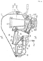
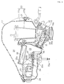
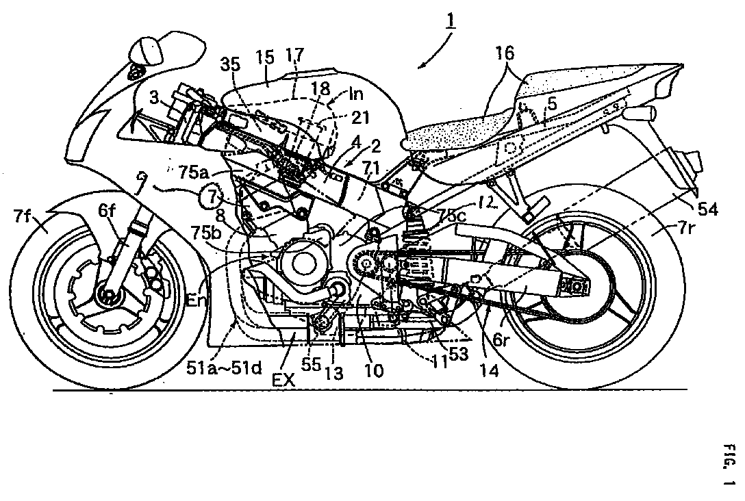
- a body frame 2 of a motorcycle 1 includes a pair of right and left main frames 4 which have a head pipe 3 at the front ends thereof, extend rearwardly, downwardly therefrom, and are connected to each other at the rear ends thereof; and seat rails 5 connected to the rear ends of the main frames 4 and extending rearwardly, upwardly therefrom.
- a parallel four-cylinder engine En is mounted on the pair of main frames 4 in such a manner that a cylinder block 8 and a cylinder head 9 are tilted slightly forwardly and the cylinder head 9 is inserted between the main frames 4.
- a front fork 6f for rotatably supporting a front wheel 7f is steerably connected to the head pipe 3.
- a rear fork 6r for supporting a rear wheel 7r is vertically swingably connected, via a pivot 11, to a rear portion of a crank case 10 of the engine En, and a rear cushion 12 is interposed between the rear fork 6r and the main frames 4.
- the rear wheel 7r is driven via a chain transmission system 14 by an output shaft 13, disposed in front of the pivot 11, of the engine En.
- a fuel tank 15 is mounted on the main frames 4, and a tandem main seat 16 is mounted on the seat rails 5.
- An intake system In of the engine En including an air cleaner 17 and throttle bodies 18 is disposed over the cylinder head 9 in such a manner as to be covered with the fuel tank 15.
- An exhaust system Ex of the engine En including exhaust pipes 51a to 51d and an exhaust muffler 54 projects from the front surfaces of the cylinder head 9 and the cylinder block 8, passes under the crank case 10, and extends obliquely, upwardly.
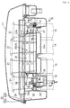
- FIG. 1 to 4 four pieces of the throttle bodies 18 corresponding to four cylinders of the engine En are connected to the cylinder head 9 of the engine En.
- Air funnels 21 are connected to inlets of intake passages 18a of the throttle valves 18.
- a cleaner case 22 of the air cleaner 17 is mounted to the four throttle valves 18 in such a manner as to house all of the air funnels 21.
- the cleaner case 22 includes a lower case half 22b fixed to the throttle bodies 18, and a upper case half 22a separably connected to the lower case half 22b with a small screw 27.
- An element mounting plate 25 for partitioning the inside of the cleaner case 22 into a lower side non-clean chamber 23 and an upper side clean chamber 24 is held between both the case halves 22a and 22b.
- a cleaner element 26 is mounted in a mounting hole 25a provided in the element mounting plate 25.
- An air inlet 28 through which the non-clean chamber 23 is opened to atmospheric air is provided in one side surface of the lower case half 22b.
- the air funnels 21 pass through a bottom wall of the lower case half 22b, and inlets of the air funnels 21 are opened to the clean chamber 24. Accordingly, during operation of the engine En, air having flowed in the non-clean chamber 23 from the air inlet 28 is filtered by the cleaner element 26 and is supplied in the clean chamber 24.
- the air supplied in the cleaner chamber 24 flows in the throttle bodies 18 through the air funnels 21.
- the flow rate of the air is adjusted by a throttle valve 29.
- the air whose flow rate has been adjusted by each throttle body 18 is then sucked in the engine En.
- fuel is injected from a fuel injection valve 32 mounted on one side wall of each throttle body 18 into an intake port of the engine En.
- Valve shafts 29a of the throttle valves 29 provided in the four throttle bodies 18 are interlocked with each other, and are operated to open/close the throttle valves 29 by a throttle grip additionally provided on a steering handlebar of the motorcycle 1 via a pulley 30 fixed on the outermost valve shaft 29a and an operating wire 31 wound around the pulley 30.
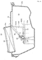
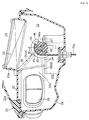
- a partition wall 34 for partitioning an intermediate portion of the non-clean chamber 23 into a lower small cross-section passage 33a and an upper large cross-section passage 33b is integrally provided on the inner side of the lower case half 22b, and an intake control valve 35 for opening/closing the large cross-section passage 33b is rotatably supported by the partition wall 34.
- the intake control valve 35 includes a valve plate 36 and a valve shaft 37 integrally provided on one end of the valve plate 36.
- One bearing 38 for rotatably supporting one end portion of the valve shaft 37 and a pair of right and left bearings 39 for rotatably supporting the other end portion of the valve shaft 37 are provided on the partition wall 34.
- the intake control valve 35 is turned between a first intake control position A (see Fig. 2) and a second intake control position B (see Fig. 3).
- first intake control position A the tip of the valve plate 36 is brought into contact with a ceiling surface of the large cross-section passage 33b to fully close the large cross-section passage 33b.
- second intake control position B the valve plate 36 is thrown down in parallel to the partition wall 34 to fully open the large cross-section passage 33b.
- the turning angle of the intake control valve 35 between the first and second intake control positions A and B is set at approximately 45°.
- the valve plate 36 is tilted with its tip directed to the upstream side of the large cross-section passage 33b, and the intake negative pressure of the engine En acts to bias the valve plate 36 in the closing direction.
- An arm 40 is integrally formed on one end portion of the valve shaft 37.
- a return spring 41 for biasing the valve plate 36 in the closing direction, that is, on the first intake control position A side via the arm 40 is connected to the arm 40.
- a driven pulley 46 is rotatably mounted on the other end portion of the valve shaft 37 at a position between the pair of bearings 39.
- the driven pulley 46 is connected to a drive pulley 73 of an actuator 71 (which will be described later) via a first transmission wire 75a.
- a lost motion mechanism 42 for connecting the driven pulley 46 and the valve shaft 37 to each other is provided between the driven pulley 46 and the valve shaft 37.
- the lost motion mechanism 42 includes a transmission pin 43 projecting from one side surface of the valve shaft 37, a circular-arc groove 44 formed in the inner peripheral surface of the driven pulley 46 and extending in the circumferential direction to be engaged with the transmission pin 43, and a lost motion spring 45 for biasing the driven pulley 46 on the first intake control position A side of the intake control valve 35.
- the center angle of the circular-arc groove 44 is set to be larger than the opening/closing angle of the intake control valve 35.
- the parallel four cylinders 50a to 50d of the engine En are arranged in this order from the left side of the vehicle, and ignition of each cylinder is performed in the order of the first, second, fourth, and third cylinders 50a, 50b, 50d and 50c.
- the first to fourth exhaust pipes 51a to 51d corresponding to the first to fourth cylinders 50a to 50d are connected to the front surface of the cylinder head 9. These exhaust pipes 51a to 51d extend downwardly along the front surface of the engine E and curve rearwardly under the engine En.
- the first and fourth exhaust pipes 51a and 51d are, under the engine En, adjacently disposed in the lateral direction, and the second and third exhaust pipes 51b and 51c are, directly under the first and fourth exhaust pipes 51a and 51d, adjacently disposed.
- An exhaust control valve 55 is provided at intermediate portions of these exhaust pipes 51a and 51d.
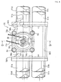
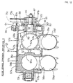
- the exhaust control valve 55 includes a common valve housing 56 interposed in the intermediate portions of the first to fourth exhaust pipes 51a to 51d, and a valve body 57 mounted in the valve housing 56.
- the upstream sides and the down stream sides of the first to fourth exhaust pipes 51a and 51d are connected to a front flange 56A and a rear flange 56B formed at both ends of the valve housing 56 in the longitudinal direction, respectively.
- the valve housing 56 has a pair of inlet ports 56a opened to the end surface of the front flange 56A and matched to the upstream pipe lines of the first and fourth exhaust piped 51a and 51d and a pair of outlet ports 56b opened to the end surface of the rear flange 56B and matched to the downstream pipe lines of the first and fourth exhaust pipes 51a and 51d; a cylindrical valve chamber 56c interposed between the inlet ports 56a and the outlet ports 56b and extending in the direction perpendicular to the axial lines of these ports; and a pair of communication ports 56d formed between the front and rear flanges 56A and 56B and matched to the upstream pipe lines and the downstream pipe lines of the second and third exhaust pipes 51b and 51c.
- a pair of communication holes 56e for communicating the communication ports 56d to the valve chamber 56c are provided on the upper side of the communication ports 56d.
- valve chamber 56c One end of the valve chamber 56c is blocked with an end wall integrated with the valve housing 56, and a bearing bush 59 is mounted in the end wall.
- the other end of the valve chamber 56c is opened and is closed with a bearing bracket 58 fixed to the valve housing 56 with a bolt 64.
- the bearing bracket 58 includes a bearing bush 60 disposed coaxially with the bearing bush 59.
- the valve body 57 is rotatably mounted in the valve chamber 56c.
- the valve body 57 is basically formed into a cylindrical shape.
- Valve shafts 61 and 62 integrally formed on both ends of the valve body 57 in the axial direction are rotatably supported by the bearing bushes 59 and 60, respectively, and are turned between a low speed control position C, a medium speed control position D, and a high speed control position E.
- the bearing bush 60 of the bearing bracket 58 projects slightly from the inner end surface of the bearing bracket 58 for supporting the end surface of the valve body 57.
- the bearing bush 60 is made from a nonmetal material excellent in not only bearing characteristic but also sealing characteristic, for example, carbon graphite.
- a driven pulley 67 is fixed to the tip portion, projecting outwardly from the bearing bracket 58, of the valve shaft 62 with a nut 65.
- the driven pulley 67 is driven via second and third transmission wires 75b and 75c by the drive pulley 73 of the actuator 71 to be described later.
- a flange portion 80 having an annular holding recess 80a opened to the bearing bracket 58 side is integrally formed on the driven pulley 67.
- An annular retainer 81 and two thrust washers 82 and 82' relatively rotatably held in the retainer 81 are housed in the holding recess 80a.
- a thrust spring 83 is provided between the thrust washers 82 and 82' and the bearing bracket 58 in such a manner as to be contracted by a specific load, whereby the end surface of the valve body 57 is pressed to the end surface of the bearing bush 60 in a sealing state. In this state, a gap “g" is formed between the end wall, opposed to the bearing bracket 58, of the valve housing 56 and the opposed end surface of the valve body 57. The gap "g” is formed to absorb thermal expansion of the valve body 57 in the axial direction.
- the valve body 57 has a pair of through-holes 57a crossing the axial line of the valve body 57 and being allowed to be matched to the inlet ports 56a and the outlet ports 56b, and communication holes 57b for opening one-sided surfaces of the through-holes 57a in the radial direction of the valve body 57.
- the communication holes 57b are matched to the inlet ports 56a of the valve housing 56 and the one-end sides of the through-holes 57a are matched to the communication holes 56e of the valve housing 56, and the outlet ports 56b are closed with valve walls 57A, opposed to the communication holes 57b, of the valve body 57.
- the through-holes 57a are matched to the inlet and outlet ports 56a and 56b, and the communication holes 56e are closed with the valve walls 57A.
- the outer surface of the valve wall 57A has a circular-arc recess 57c which is continuous to the inner peripheral surface of the communication port 56d at the medium speed control position D (see Fig. 11).
- the through-holes 57a are matched to the inlet and outlet ports 56a and 56b, and the communication holes 57b are matched to the communication holes 56e. Accordingly, the medium speed control position D and the high speed control position E of the valve body 57 are separated from each other by about 180° and the low speed control position C is present at an intermediate point therebetween.
- the first and fourth exhaust pipes 51a and 51d are connected to an upper first exhaust collection pipe 52a for collecting the first and fourth exhaust pipes 51a and 51d
- the second and third exhaust pipes 51b and 51c are connected to a lower first exhaust collection pipe 52b for collecting the second and third exhaust pipes 51b and 51c.
- the exhaust collection pipes 52a and 52b are connected to a second exhaust collection pipe 53 for collecting the exhaust collection pipes 52a and 52b
- the exhaust muffler 54 is connected to the rear end of the second exhaust collection pipe 53.
- first exhaust collection pipe 52a and 52b Of the upper and lower first exhaust collection pipes 52a and 52b, only the lower first exhaust collection pipe 52b connected to the communication ports 56d of the exhaust control valve 55 is provided with a primary exhaust purifying system 84, and the second exhaust collection pipe 53 is provided with a secondary exhaust purifying system 85.
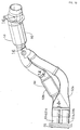
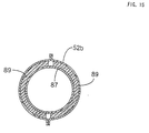
- the type of the primary exhaust purifying system 84 is not particularly limited, but according to this embodiment, the primary exhaust purifying system 84 is configured as a three way catalytic converter as shown in Figs. 14 and 15, which mainly includes a circular catalyst support 87 having a large number of through-holes 88 formed in its peripheral wall.
- the catalyst support 87 is held in the lower first exhaust collection pipe 52b in such a manner that one end portion is welded to the inner wall of the lower first exhaust collection pipe 52b and the other end portion is slidably held by the same inner wall via a heat insulation member 89 made from glass wool, steel wool, or the like, and a cylindrical heat insulation space 90 is provided between an intermediate portion of the catalyst support 87 excluding both the ends and the lower first exhaust collection pipe 52b. Accordingly, thermal extension of the primary exhaust purifying system 84 is permitted by a sliding motion of the primary exhaust purifying system 84 against the heat insulation member 89, so that it is possible to suppress occurrence of thermal strain of the primary exhaust purifying system 84 and the lower first exhaust collection pipe 52b. By the presence of the heat insulation member 89 and the heat insulation space 90, it is possible to thermally insulate the primary exhaust purifying system 84 and to prevent the over-heating of the lower first exhaust collection pipe 52b.
- the second exhaust collection pipe 53 includes an outer pipe 92 extending on the upstream side and an inner pipe 93 extending on the downstream side.
- the inner pipe 93 is disposed in the outer pipe 92 with a cylindrical heat insulation space 94 put therebetween.
- the downstream end of the outer pipe 92 is welded to the outer periphery of the inner pipe 93, and the upstream end of the inner pipe 93 is relatively slidably supported by the outer pipe 92 via a heat insulation member 95 made from glass wool, steel wool, or the like.
- An intermediate portion of the second exhaust collection pipe 53 is slightly bent, and at the bent portion, a guide ring 96 surrounding the inner pipe 93 is welded to the inner peripheral surface of the outer pipe 92.
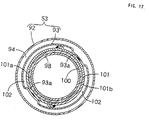
- the type of the secondary exhaust purifying system 85 is not particularly limited, but according to this embodiment, the secondary exhaust purifying system 85 is configured as a three way catalytic converter as shown in Figs. 16 and 17, which mainly includes a circular catalyst support 98 having a large number of through-holes 99 formed in its peripheral wall.
- the catalyst support 98 is mounted, at its axial central portion, to the inner pipe 93 via a heat insulation member 100 and a retainer ring 101.
- the heat insulation member 100 is made from glass wool, steel wool, or the like.
- the retainer ring 101 is formed by overlapping and welding end portions, opposed to each other, of a pair of semi-annular bodies 101a and 101b to each other.
- the inner pipe 93 has a pair of projections 93a projecting radially inwardly and opposed to each other in the diameter direction.
- the outer peripheral surface of the retainer ring 101 is welded to the projections 93a, and a heat insulation space 102 is provided between the retainer ring 101 and the inner pipe 93 while excluding the welded portion.
- a portion, other than the central portion retained by the retainer ring 101, of the catalyst support 98 is sufficiently separated from the inner peripheral surface of the inner pipe 93 for allowing exhaust gas to flow in or out of the catalyst support 98 through the large number of through-holes 99.
- the thermal extension of the secondary exhaust purifying system 85 is permitted by a sliding motion of the secondary exhaust purifying system 85 against the heat insulation member 100, so that it is possible to suppress occurrence of the thermal strain of the secondary exhaust purifying system 85 and the inner pipe 93.
- the thermal extension of the secondary exhaust purifying system 85 is permitted by a sliding motion of the secondary exhaust purifying system 85 against the heat insulation member 100, so that it is possible to suppress occurrence of the thermal strain of the secondary exhaust purifying system 85 and the inner pipe 93.
- the heat insulation member 100, heat insulation space 102, inner pipe 93, and heat insulation space 94 located outside the inner pipe 93 it is possible to reserve the heat of the secondary exhaust purifying system 85 and to prevent the over-heating of the outer pipe 92.
- the secondary exhaust purifying system 85 Since the secondary exhaust purifying system 85 is stably retained at one retaining portion and exhaust gas is allowed to flow in or out of the catalyst support 98 through the through-holes 88 at the portion other than the retaining portion, it is possible to effectively purify the exhaust gas.
- the difference in thermal extension between the outer pipe 92 and the inner pipe 93 constituting the secondary exhaust collection pipe 53 is permitted by a sliding motion between the inner pipe 93, heat insulation member 95, and outer pipe 92.
- By the presence of the double heat insulation spaces 94 and 102 between the secondary exhaust purifying system 85 and the outer pipe 92 it is possible to effectively prevent the thermal deterioration of the secondary exhaust purifying system 85.
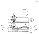
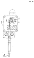
- a pair of brackets 70 are fixed on the inner surface of the main frame 4 at a position over the crank case 10 of the engine En, and the common actuator 71 is mounted via an elastic member 77 to the brackets 70 with a bolt 78.
- the actuator 71 is disposed such that a distance between the intake control valve 35 and the same is nearly equal to a distance between the exhaust control valve 55 and the same.
- the actuator 71 is configured as a normally/reversely rotatable electric motor.
- the drive pulley 73 fixed to the output shaft 72 of the motor has a small-diameter first wire groove 73a, and large-diameter second and third transmission wire grooves 73b and 73c.
- a first transmission wire 75a is engaged in both the first wire groove 73a and a wire groove 46a of the driven pulley 46 (see Fig. 6) on the intake control valve 35 side, and both terminals of the wire 75a are connected to the drive pulley 73 and the driven pulley 46.
- the second and third transmission wires 75b and 75c are respectively engaged in the second and third wire grooves 73b and 73c and a pair of wire grooves 67b and 67c of the driven pulley 67 (see Fig.
- An electronic control unit 76 connected to the actuator 71 decides a low speed rotational range, a medium speed rotational range, and a high speed rotational range of the engine En on the basis of the speed of the engine En, boosted negative pressure, and the like inputted from sensors (not shown), and controls the actuator 71 in accordance with the decided rotational range. In this way, as shown in Fig.
- the actuator 71 holds the drive pulley 73 at an initial position "a" in the medium speed rotational range of the engine En; drives the drive pulley 73 from the initial position "a” to a first drive position “b” separated therefrom in the reversal rotation direction R by a specific angle in the low speed rotational range; and drives the drive pulley 73 from the first drive position "b” to a second drive position "c" separated therefrom while passing through the initial position "a” in the normal rotation direction F by a specific angle in the high speed rotational range.
- the drive pulley 73 When the drive pulley 73 is driven to the first drive position "b" by the actuator 71 in the low speed rotational range of the engine En, the drive pulley 73 pulls the first and second transmission wires 75a and 75b to turn the driven pulley 46 on the intake control valve 35 side in the valve opening direction (counterclockwise in Fig. 6) by a specific angle, and to turn the driven pulley 67 on the exhaust control valve 35 side counterclockwise in Fig. 8 by a specific angle for moving the valve body 57 of the exhaust control valve 35 to the low speed control position C shown in Figs. 9 and 10.
- the rotation of the driven pulley 46 by the specific angle is performed within the range of the play angle ⁇ between the drive pulley 73 and the intake control valve 35 in the lost motion mechanism 42, and accordingly, the valve plate 36 of the intake control valve 35 is held at the first intake control position A by the biasing force of the return spring 41.
- valve body 57 of the exhaust control valve 55 When the valve body 57 of the exhaust control valve 55 is moved to the low speed control position C shown in Figs. 9 and 10, as described above, the communication holes 57b of the valve body 57 are matched to the inlet ports 56a of the valve housing 56 and the one-end sides of the through-holes 57a of the valve body 57 are matched to the communication holes 56e of the valve housing 56, and the output ports 56b are closed with the valve walls 57A of the valve body 57.
- the exhaust resistance is increased, to apply an exhaust pressure suitable for the low speed rotational range from the exhaust pipes 51a to 51d to the engine En, thereby improving the low speed output performance by suppressing the blow-by of a new air from the cylinders 50a to 50d into the exhaust system during the valve overlapping period.
- the exhaust gases having passed through the communication ports 56d of the valve housing 56 collectively flow in the lower first exhaust collection pipe 52b by way of the downstream sides of the second and third exhaust pipes 51b and 51c, and the joined exhaust gas is purified by the primary exhaust purifying system 84. Accordingly, the exhaust gases generated by the engine En all flow in the primary exhaust purifying system 84, and since the primary exhaust purifying system 84 is thermally insulated as described above, the primary exhaust purifying system 84 can be early activated, even directly after start-up of the engine En, by the exhaust heat and reaction heat.
- the exhaust gas having passed through the lower first exhaust collection pipe 52b is fed to the second exhaust collection pipe 53, and is further purified by the secondary exhaust purifying system 85. Since the secondary exhaust purifying system 85 is also thermally insulated as described above, it is possible to promote activation of the secondary exhaust purifying system 85.
- the downstream sides of the first and fourth exhaust pipes 51a and 51d are closed with the valve walls 57A of the valve body 57 to block the flow of the exhaust gases to the upper first exhaust collection pipe 52a, and accordingly, it is not required to provide any exhaust purifying system to the upper first exhaust collection pipe 52a.
- the drive pulley 73 loosens the first transmission wire 75a and pulls the third transmission wire 75c.
- the loosening of the first transmission wire 75a allows the driven pulley 46 on the intake control valve 35 side to be only returned to the initial position shown in Fig. 6 within the range of the play angle ⁇ by the biasing force of the lost motion spring 45. At this time, there occurs no change of the intake control valve 35 located at the first intake control position A.
- the driven pulley 67 on the exhaust control valve 55 side is turned by pulling the third transmission wire 75c, to, move the valve body 57 to the medium speed control position D shown in Fig. 9.
- the through-holes 57a of the valve body 57 are matched to the inlet and outlet ports 56a and 56b of the valve housing 56 and the communication holes 56e are closed with the valve walls 57A, so that the first to fourth exhaust pipes 51a to 51d individually allow exhaust gases to pass therethrough.
- valve body 57 since the through-holes 57a of the valve body 57 are matched to the pipe lines of the first and fourth exhaust pipes 51a and 51d via the inlet and outlet ports 56a and 56b, it is possible to equalize the cross-section of the pipe line of each of the first and fourth exhaust pipes 51a and 51d over the entire length.
- each of the first to fourth exhaust pipes 51a to 51d achieves an effective exhaust inertia effect and/or an effective exhaust pulsation effect by making use of the equalized cross-section thereof over the entire length.
- the effective pipe length of each of the exhaust pipes 51a to 51d becomes the maximum length extending from the engine En to the upper and lower first exhaust collection pipes 52a and 52b.
- the maximum effective pipe length is set such that the exhaust inertia effect and/or the exhaust pulsation effect due to the maximum pipe length enhance the volume efficiency of the engine En in the medium speed rotational range. As a result, it is possible to enhance the medium speed output performance of the engine En.
- the drive pulley 73 When the rotational state of the engine En is shifted to the high speed rotational range and the drive pulley 73 is driven to the second drive position "c" by the actuator 71, the drive pulley 73 largely pulls the first and second transmission wires 75a and 75b.
- the large pull of the first transmission wire 75a turns the driven pulley 46 on the intake control valve 35 side in the valve opening direction largely over the play angle ⁇ , to bring the one end wall of the circular-arc groove 44 into contact with the transmission pin 44 of the intake control valve 35, thereby moving the valve plate 36 of the intake control valve 35 to the second intake control position B shown in Fig. 3.
- the large pull of the second transmission wire 75b turns the driven pulley 67 on the exhaust control valve 55 side by about 180° , thereby shifting the valve body 57 from the medium control position D to the high speed control position E shown in Fig. 12 while passing through the low speed control position C.
- valve plate 36 of the intake control valve 35 When the valve plate 36 of the intake control valve 35 reaches the second intake control position B, as shown in Fig. 3, the valve plate 36 fully opens the large cross-section passage 33b, with a result that air sucked in the engine En can pass through both the large cross-section passage 33b and the small cross-section passage 33a of the air cleaner 17. Accordingly, it is possible to reduce the intake resistance, and hence to enhance the volume efficiency of the engine En and improve the high speed output performance.
- valve body 57 of the exhaust control valve 55 reaches the high speed control position E, as described above, the through-holes 57a of the valve body 57 are matched to the inlet and outlet ports 56a and 56b of the valve housing 56 and the communication holes 57b of the valve body 57 are matched to the communication holes 56e of the valve housing 56, and accordingly, the exhaust gas passing states of the first to fourth exhaust pipes 51a to 51d are not changed; however, the intermediate portions of the first and fourth exhaust pipes 51a and 51d are communicated to the communication holes 56e and the intermediate portions of the second and third exhaust pipes 51b and 51c are communicated to the communication holes 57b.
- the effective length of each of the exhaust pipes 51a to 51d becomes the minimum length extending from the engine En to the exhaust control valve 55.
- the minimum effective pipe length is set such that the exhaust inertia effect and/or the exhaust pulsation effect due to the minimum pipe length enhance the volume efficiency of the engine En in the high speed rotational range. As a result, it is possible to enhance the high speed output performance of the engine En.
- the exhaust gases having passed through the first and fourth exhaust pipes 51a and 51d are joined to each other at the upper first exhaust collection pipe 52a, and the joined exhaust gas flows to the second exhaust collection pipe 53, while the exhaust gases having passed through the second and third exhaust pipes 51b and 51c are joined to each other at the lower first exhaust collection pipe 52b and purified by the primary exhaust purifying system 84, and the joined and purified exhaust gas flows to the second exhaust collection pipe 53; and all the exhaust gases joined to each other at the second exhaust collection pipe 53 are purified by the secondary exhaust purifying system 85.
- the exhaust gases having passed through the first and fourth exhaust pipes 51a and 51d are purified only by the secondary exhaust purifying system 85; however, there occurs no problem on the basis of the following reason; namely, the flow rate of the exhaust gases becomes relatively large in the medium or high speed operational range, so that the purifying function of the secondary exhaust purifying system 85 is sufficiently enhanced by the exhaust heat and reaction heat due to the large amount of the exhaust gases, with a result that all of the exhaust gases are effectively purified.
- the actuator 71 is used commonly between both the control valves 35 and 55, it is possible to simplify the configuration of the drive system for driving both the control valves 35 and 55, and hence to improve the engine performance while reducing the cost of the drive system and further reduce the weight of the drive system.
- the bearing bush 60, on the driven pulley 67 side, of the valve housing 56 of the exhaust control valve 55 not only supports one valve shaft 62 of the valve body 57 but also receives one end surface of the valve body 57 biased to the bearing bush 60 side due to a load applied to the thrust spring 83.
- the bearing bush 60 is pressed to the one end surface of the valve body 57 in a sealing state, so that the contact area between valve body 57 and the bearing bush 60 can be sealed to thereby prevent the leakage of the exhaust gas from the bearing bush 60 side, without use of any special seal member.
- the elimination of the need of provision of any seal member is effective to reduce the number of parts and to reduce the cost.
- the use of the bearing bush 60 made from a nonmetal material such as carbon graphite makes it possible to ensure a desirable sealing performance, and to suppress the occurrence of noise by absorbing vibration of the valve body 57 occurring in the thrust direction due to exhaust pulsation.
- the intake control valve 35 may be configured such that the effective pipe length of the intake system In is variable depending on the operational state of the engine En.
- the present invention can be applied to a two-cylinder engine, wherein two exhaust pipes of the engine can be controlled by the exhaust control valve 55 like the first and fourth exhaust pipes 51a and 51d and the second and third exhaust pipes 51b and 51c.
- the present invention can be also applied to other multi-cylinder engines.
Landscapes
- Engineering & Computer Science (AREA)
- Chemical & Material Sciences (AREA)
- Combustion & Propulsion (AREA)
- Mechanical Engineering (AREA)
- General Engineering & Computer Science (AREA)
- Biomedical Technology (AREA)
- Health & Medical Sciences (AREA)
- Characterised By The Charging Evacuation (AREA)
- Control Of Throttle Valves Provided In The Intake System Or In The Exhaust System (AREA)
- Exhaust Gas After Treatment (AREA)
- Electrical Control Of Air Or Fuel Supplied To Internal-Combustion Engine (AREA)
- Combined Controls Of Internal Combustion Engines (AREA)
- Exhaust Silencers (AREA)
- Output Control And Ontrol Of Special Type Engine (AREA)
Abstract
Description
- The present invention relates to intake and exhaust control systems for an engine, in which an intake control valve for changing an intake mode in accordance with an operational state of an engine is provided in an intake system of the engine and an exhaust control valve for changing an exhaust mode in accordance with an operational state of the engine is provided, in an exhaust system of the engine, characterized by ensuring a desired output performance in accordance with a change in operational state.
- An intake control system, wherein an intake system for an engine has an intake control valve operated between a first intake control position at which it gives a low speed side compatible function to the intake system and a second intake control position at which it gives a high speed side compatible function to the intake system, has been disclosed, for example, in Japanese Patent Laid-open No. Sho 58-155270. Further, an exhaust control system, wherein an exhaust system for an engine has an exhaust control valve operated between a first exhaust control position at which it gives a low speed side compatible function to the exhaust system and a second exhaust control position at which it gives a high speed side compatible function to the exhaust system, has been disclosed, for example, in Japanese Patent Publication No. Hei 6-76780.
- By the way, if the above-described intake control valve and exhaust control valve are provided in an intake system and an exhaust system of the same engine, respectively, the output performance in a wide rotational range of the engine can be further improved. In this case, if the control valves are individually driven by separate actuators, the number of parts is increased, thereby giving rise to a problem in raising the cost.
- In view of the foregoing, the present invention has been made, and an object of the present invention is to provide intake and exhaust control systems for an engine, including an intake control valve and an exhaust control valve provided in an intake system and an exhaust system of the engine respectively, which systems are capable of further improving the output performance of the engine in a wide operational region including a low speed rotational range and a high speed rotational range and simply driving both the control valves, thereby satisfying requirements in terms of both performance and economy.
- To achieve the above object, according to a first feature of the present invention, there is provided intake and exhaust control systems for an engine, characterized in that an intake control valve for changing an intake mode in accordance with an operational state of an engine is provided in an intake system of the engine and an exhaust control valve for changing an exhaust mode in accordance with an operational state of the engine is provided in an exhaust system of the engine; and the intake control valve and the exhaust control valve are driven by a common actuator.
- With this first feature, it is possible to effectively obtain a desired output performance of the engine irrespective of a change in operational state of the engine by operating the intake control valve and the exhaust control valve in accordance with the operational state of the engine by the actuator. Further, since the intake control valve and the exhaust control valve are driven by the common single actuator, it is possible to simplify the configuration of the drive system and hence to improve the engine performance and reduce the cost of the drive system, and also to reduce the weight of the drive system.
- According to a second feature of the present invention, in addition to the first feature, the intake control valve is operated between a first intake control position at which the intake control valve gives a low speed side compatible function to the intake system and a second intake control position at which the intake control valve gives a high speed side compatible function to the intake system; and the exhaust control valve is operated between a first exhaust control position at which the exhaust control valve gives a low speed side compatible function to the exhaust system and a second exhaust control position at which the exhaust control valve gives a high speed side compatible function to the exhaust system. In addition, the first exhaust control position and the second exhaust control position of the exhaust control valve are equivalent to a medium speed control position D and a high speed control position E of a
valve body 57 of anexhaust control valve 55 in an embodiment of the present invention to be described later. - With this second feature, since at the low speed rotational range of the engine, the intake control valve and the exhaust control valve are held at the first intake control position and the first exhaust control position by the actuator, respectively, it is possible to give the low speed side compatible function to both the intake system and the exhaust system, and hence to effectively enhance the low speed side output performance of the engine. When the rotational state of the engine is shifted to the high speed rotational range, since the intake control valve and the exhaust control valve are moved to the second intake control position and the second exhaust control position by the actuator, respectively, it is possible to give the high speed side compatible function to both the intake system and the exhaust system, and hence to effectively enhance the high speed side output performance of the engine.
- According to a third feature of the present invention, in addition to the first or second feature, a lost motion mechanism for absorbing a difference in operational amount between the intake control valve and the exhaust control valve is provided between the actuator and the intake control valve or between the actuator and the exhaust control valve.
- With this third feature, even if there is a large difference between the operational amounts of the intake control valve and the exhaust control valve, such a difference can be absorbed by the lost motion mechanism, so that both the control valves can be certainly operated by the common actuator.
- According to a fourth feature of the present invention, there is provided an exhaust control system for an engine, characterized in that the system includes an exhaust control valve, the exhaust control valve including a common valve housing interposed on the way of a first exhaust pipe and a second exhaust pipe connected to cylinders different in ignition timing and a valve body mounted in the valve housing and switchingly turned between a low speed control position, a medium speed control position, and a high speed control position, wherein at the low speed control position of the valve body, the first exhaust pipe is communicated to the second exhaust pipe and the first exhaust pipe is closed on the downstream side of the communicated portion; at the medium speed control position, the first exhaust pipe and the second exhaust pipe individually allow exhaust gases to pass therethrough; and at the high speed control position, the first exhaust pipe and the second exhaust pipe individually allow exhaust gases to pass therethrough, and an intermediate portion of the first exhaust pipe is communicated to an intermediate portion of the second exhaust pipe. In addition, the first exhaust pipe is equivalent to first and
fourth exhaust pipes third exhaust pipes - With this fourth feature, exhaust gas flowing in the first exhaust pipe is curved, on the way, onto the second exhaust pipe side by controlling the valve body at the low speed control position, to increase the exhaust resistance, so that it is possible to apply an exhaust pressure suitable for the low speed rotational range to the engine, and hence to improve the low speed output performance by suppressing the blow-by of a new air from each cylinder to the exhaust system during the valve overlapping period. The effective pipe length of each of the first and second exhaust pipes is set at the maximum length matched to the medium speed operational range of the engine by controlling the valve body at the medium speed control position, to enhance the volume efficiency by making use of an exhaust inertia effect and/or an exhaust pulsation effect, thereby increasing the medium speed output performance of the engine. Further, the effective pipe length of each of the first and second exhaust pipes is set at the minimum length matched to the high speed operational range of the engine by controlling the valve body at the high speed control position, to enhance the volume efficiency by making use of the exhaust inertia effect and/or the exhaust pulsation effect, thereby increasing the high speed output performance of the engine.
- According to a fifth feature of the present invention, in addition to the fourth feature, the valve body is supported in the valve housing in such a manner as to be turned between the low speed control position, the medium speed control position, and the high speed control position, and the valve body has a through-hole crossing the axial line of the valve body and a communication hole for opening one side surface of the through-hole in the radial direction of the valve body; and at the low speed control position of the valve body, the communication hole and the through-hole are concerned with the mutual communication of the first exhaust pipe and the second exhaust pipe, and a valve wall, opposed to the communication hole, of the valve body is concerned with the closing of the downstream side of the first exhaust pipe; at the medium control position, the through-hole is matched to the pipe line of the first exhaust pipe, and the valve wall is concerned with the blocking between the first exhaust pipe and the second exhaust pipe; and at the high speed control position, the through-hole is matched to the pipe line of the first exhaust pipe, and the communication hole is concerned to the communication between the first exhaust pipe and the second exhaust pipe.
- With this fifth feature, it is possible to equalize the cross-section of the pipe line of each exhaust pipe over the effective pipe length matched to each operational range of the engine irrespective of the presence of the valve body, and hence to obtain effective exhaust inertia effect and/or exhaust pulsation effect matched to each operational range. In particular, when the valve body is controlled at the medium speed control position, it is possible to equalize the cross-section of the pipe line of each exhaust pipe over the entire length, and hence to significantly obtain the above-described effect and improve the medium speed output performance of the engine.
- According to a sixth feature of the present invention, in addition to the fourth feature, of the first exhaust pipe and the second exhaust pipe on the downstream side from the valve housing, only the second exhaust pipe is connected to a primary exhaust purifying system; the first exhaust pipe and the second exhaust pipe are connected to an exhaust collection pipe on the downstream side from the primary exhaust purifying system; and a secondary exhaust purifying system is provided in the exhaust collection pipe. The exhaust collection pipe is equivalent to a second
exhaust collection pipe 53 in the embodiment of the present invention to be described later. - With this sixth feature, in the low speed operational range of the engine in which the flow rate of exhaust gas is relatively small, the valve body is controlled at the low speed control position. In this case, all of the exhaust gas having passed through the valve housing can be sequentially introduced to the primary and secondary purifying systems, to thereby desirably purifying the exhaust gas; the primary exhaust purifying system can be heated to an activation temperature at an early stage; and the entire cost of the exhaust purifying systems can be reduced because any exhaust purifying system is not provided on the first exhaust pipe side. In the medium or high speed operational range of the engine, the valve body is controlled at the medium or high speed control position. In this case, the exhaust gas having passed through the first exhaust pipe does not pass through the primary exhaust purifying system; however, in such a state, the flow rate of the exhaust gas becomes relatively large and all of the amount of the exhaust gas passes through the secondary exhaust purifying system, so that the purifying function of the secondary exhaust purifying system is sufficiently enhanced by the exhaust heat of the large amount of the exhaust gas and the reaction heat and thereby all the exhaust gas can be effectively purified.
- As described above, according to the first feature of the present invention, there is provided intake and exhaust control systems for an engine, characterized in that an intake control valve for changing an intake mode in accordance with an operational state of an engine is provided in an intake system of the engine and an exhaust control valve for changing an exhaust mode in accordance with an operational state of the engine is provided in an exhaust system of the engine; and the intake control valve and the exhaust control valve are driven by a common actuator. Accordingly, it is possible to effectively obtain a desired output performance of the engine irrespective of a change in operational state of the engine by operating the intake control valve and the exhaust control valve in accordance with the operational state of the engine by the actuator. Further, since the intake control valve and the exhaust control valve are driven by the common single actuator, it is possible to simplify the configuration of the drive system and hence to improve the engine performance and reduce the cost of the drive system, and also to reduce the weight of the drive system.
[0070] - According to the second feature of the present invention, the intake control valve is operated between a first intake control position at which the intake control valve gives a low speed side compatible function to the intake system and a second intake control position at which the intake control valve gives a high speed side compatible function to the intake system; and the exhaust control valve is operated between a first exhaust control position at which the exhaust control valve gives a low speed side compatible function to the exhaust system and a second exhaust control position at which the exhaust control valve gives a high speed side compatible function to the exhaust system. Accordingly, it is possible to effectively enhance the output performance in a wide operational region of the engine from the low speed operational range to the high speed rotational range by operation of the intake control valve between the first and second intake control positions by means of the actuator, and operation of the exhaust control valve between the first and second exhaust control positions by means of the actuator.
- According to the third feature of the present invention, a lost motion mechanism for absorbing a difference in operational amount between the intake control valve and the exhaust control valve is provided between the actuator and the intake control valve or between the actuator and the exhaust control valve, and accordingly, even if there is a large difference between the operational amounts of the intake control valve and the exhaust control valve, both the control valves can be certainly operated by the common actuator.
- According to the fourth feature of the present invention, there is provided an exhaust control system for an engine, characterized in that the system includes an exhaust control valve, the exhaust control valve including a common valve housing interposed on the way of a first exhaust pipe and a second exhaust pipe connected to cylinders different in ignition timing and a valve body mounted in the valve housing and switchingly turned between a low speed control position, a medium speed control position, and a high speed control position, wherein at the low speed control position of the valve body, the first exhaust pipe is communicated to the second exhaust pipe and the first exhaust pipe is closed on the downstream side of the communicated portion; at the medium speed control position, the first exhaust pipe and the second exhaust pipe individually allow exhaust gases to pass therethrough; and at the high speed control position, the first exhaust pipe and the second exhaust pipe individually allow exhaust gases to pass therethrough, and an intermediate portion of the first exhaust pipe is communicated to an intermediate portion of the second exhaust pipe. Accordingly, the output performance in each operational range can be improved by controlling the valve body at the low speed, medium speed, or high speed control position in accordance with the low speed, medium speed, or high speed operational range of the engine, thereby increasing the back pressure of the engine or changing the effective pipe length of each exhaust pipe.
- According to the fifth feature of the present invention, the valve body is supported in the valve housing in such a manner as to be turned between the low speed control position, the medium speed control position, and the high speed control position, and the valve body has a through-hole crossing the axial line of the valve body and a communication hole for opening one side surface of the through-hole in the radial direction of the valve body; and at the low speed control position of the valve body, the communication hole and the through-hole are concerned with the mutual communication of the first exhaust pipe and the second exhaust pipe, and a valve wall, opposed to the communication hole, of the valve body is concerned with the closing of the downstream side of the first exhaust pipe; at the medium control position, the through-hole is matched to the pipe line of the first exhaust pipe, and the valve wall is concerned with the blocking between the first exhaust pipe and the second exhaust pipe; and at the high speed control position, the through-hole is matched to the pipe line of the first exhaust pipe, and the communication hole is concerned to the communication between the first exhaust pipe and the second exhaust pipe. Accordingly, it is possible to equalize the cross-section of the pipe line of each exhaust pipe over the effective pipe length matched to each operational range of the engine irrespective of the presence of the valve body, and hence to obtain effective exhaust inertia effect and/or exhaust pulsation effect matched to each operational range. In particular, when the valve body is controlled at the medium speed control position, it is possible to equalize the cross-section of the pipe line of each exhaust pipe over the entire length, and hence to significantly obtain the above-described effect and improve the medium speed output performance of the engine.
- According to the sixth feature of the present invention, of the first exhaust pipe and the second exhaust pipe on the downstream side from the valve housing, only the second exhaust pipe is connected to a primary exhaust purifying system; the first exhaust pipe and the second exhaust pipe are connected to an exhaust collection pipe on the downstream side from the primary exhaust purifying system; and a secondary exhaust purifying system is provided in the exhaust collection pipe. Accordingly, in the low speed operational range of the engine in which the flow rate of exhaust gas is relatively small, the valve body is controlled at the low speed control position. In this case, all of the exhaust gas having passed through the valve housing can be sequentially introduced to the primary and secondary purifying systems, to thereby desirably purifying the exhaust gas; the primary exhaust purifying system can be heated to an activation temperature at an early stage; and the entire cost of the exhaust purifying systems can be reduced because any exhaust purifying system is not provided on the first exhaust pipe side. Further, in the medium or high speed operational range of the engine, the valve body is controlled at the medium or high speed control position. In this case, the exhaust gas having passed through the first exhaust pipe does not pass through the primary exhaust purifying system; however, in such a state, the flow rate of the exhaust gas becomes relatively large and all of the amount of the exhaust gas passes through the secondary exhaust purifying system, so that the purifying function of the secondary exhaust purifying system is sufficiently enhanced by the exhaust heat of the large amount of the exhaust gas and the reaction heat and thereby all of the exhaust gas can be effectively purified.
- Hereinafter, one embodiment of the present invention will be described with reference to the accompanying drawings.
-
- Fig. 1
A side view of a motorcycle including intake and exhaust control systems for an engine according to the present invention. - Fig. 2
A vertical sectional side view showing an essential portion of the intake control system. - Fig. 3
A view illustrating the function of the intake control system shown in Fig. 2. - Fig. 4
A sectional view taken on line 4-4 of Fig. 2. - Fig. 5
A sectional view taken on line 5-5 of Fig. 4. - Fig. 6
A sectional view taken on line 6-6 of Fig. 4. - Fig. 7
A perspective view of an exhaust system. - Fig. 8
A side view of the exhaust control system. - Fig. 9
A sectional view taken on line 9-9 of Fig. 8, showing an exhaust control valve located at a low speed control position. - Fig. 10
A sectional view taken on line 10-10 of Fig. 9. - Fig. 11
A sectional view, similar to Fig. 9, showing the exhaust control valve located at a medium speed control position. - Fig. 12
A sectional view, similar to Fig. 9, showing the exhaust control valve located at a high speed control position. - Fig. 13
An enlarged plan view showing an essential portion of an exhaust system. - Fig. 14
A sectional view taken on line 14-14 of Fig. 13. - Fig. 15
A sectional view taken on line 15-15 of Fig. 14. - Fig. 16
A sectional view taken on line 16-16 of Fig. 13. - Fig. 17
A sectional view taken on line 17-17 of Fig. 16. - Fig. 18
A plan view showing a drive system for driving the intake control valve and the exhaust control valve. - Fig. 19
A sectional view taken on line 19-19 of Fig. 18. - Fig. 20
A sectional view taken on line 20-20 of Fig. 18. -
- Referring to Fig. 1, a body frame 2 of a
motorcycle 1 includes a pair of right and left main frames 4 which have a head pipe 3 at the front ends thereof, extend rearwardly, downwardly therefrom, and are connected to each other at the rear ends thereof; andseat rails 5 connected to the rear ends of the main frames 4 and extending rearwardly, upwardly therefrom. A parallel four-cylinder engine En is mounted on the pair of main frames 4 in such a manner that a cylinder block 8 and a cylinder head 9 are tilted slightly forwardly and the cylinder head 9 is inserted between the main frames 4. - A
front fork 6f for rotatably supporting afront wheel 7f is steerably connected to the head pipe 3. Arear fork 6r for supporting arear wheel 7r is vertically swingably connected, via a pivot 11, to a rear portion of a crankcase 10 of the engine En, and arear cushion 12 is interposed between therear fork 6r and the main frames 4. Therear wheel 7r is driven via achain transmission system 14 by anoutput shaft 13, disposed in front of the pivot 11, of the engine En. - A
fuel tank 15 is mounted on the main frames 4, and a tandemmain seat 16 is mounted on the seat rails 5. - An intake system In of the engine En including an
air cleaner 17 andthrottle bodies 18 is disposed over the cylinder head 9 in such a manner as to be covered with thefuel tank 15. An exhaust system Ex of the engine En includingexhaust pipes 51a to 51d and anexhaust muffler 54 projects from the front surfaces of the cylinder head 9 and the cylinder block 8, passes under thecrank case 10, and extends obliquely, upwardly. - Referring to Figs. 1 to 6, the intake system In of the engine En will be first described.
- Referring to Figs. 1 to 4, four pieces of the
throttle bodies 18 corresponding to four cylinders of the engine En are connected to the cylinder head 9 of the engine En. Air funnels 21 are connected to inlets ofintake passages 18a of thethrottle valves 18. Acleaner case 22 of theair cleaner 17 is mounted to the fourthrottle valves 18 in such a manner as to house all of the air funnels 21. Thecleaner case 22 includes alower case half 22b fixed to thethrottle bodies 18, and aupper case half 22a separably connected to thelower case half 22b with asmall screw 27. Anelement mounting plate 25 for partitioning the inside of thecleaner case 22 into a lower sidenon-clean chamber 23 and an upper sideclean chamber 24 is held between both the case halves 22a and 22b. Acleaner element 26 is mounted in a mountinghole 25a provided in theelement mounting plate 25. - An
air inlet 28 through which thenon-clean chamber 23 is opened to atmospheric air is provided in one side surface of thelower case half 22b. On the other hand, the air funnels 21 pass through a bottom wall of thelower case half 22b, and inlets of the air funnels 21 are opened to theclean chamber 24. Accordingly, during operation of the engine En, air having flowed in thenon-clean chamber 23 from theair inlet 28 is filtered by thecleaner element 26 and is supplied in theclean chamber 24. The air supplied in thecleaner chamber 24 flows in thethrottle bodies 18 through the air funnels 21. In each of thethrottle bodies 18, the flow rate of the air is adjusted by athrottle valve 29. The air whose flow rate has been adjusted by eachthrottle body 18 is then sucked in the engine En. At this time, fuel is injected from afuel injection valve 32 mounted on one side wall of eachthrottle body 18 into an intake port of the engine En. -
Valve shafts 29a of thethrottle valves 29 provided in the fourthrottle bodies 18 are interlocked with each other, and are operated to open/close thethrottle valves 29 by a throttle grip additionally provided on a steering handlebar of themotorcycle 1 via apulley 30 fixed on theoutermost valve shaft 29a and anoperating wire 31 wound around thepulley 30. - A
partition wall 34 for partitioning an intermediate portion of thenon-clean chamber 23 into a lowersmall cross-section passage 33a and an upperlarge cross-section passage 33b is integrally provided on the inner side of thelower case half 22b, and anintake control valve 35 for opening/closing thelarge cross-section passage 33b is rotatably supported by thepartition wall 34. - The
intake control valve 35 includes avalve plate 36 and avalve shaft 37 integrally provided on one end of thevalve plate 36. Onebearing 38 for rotatably supporting one end portion of thevalve shaft 37 and a pair of right and leftbearings 39 for rotatably supporting the other end portion of thevalve shaft 37 are provided on thepartition wall 34. - The
intake control valve 35 is turned between a first intake control position A (see Fig. 2) and a second intake control position B (see Fig. 3). At the first intake control position A, the tip of thevalve plate 36 is brought into contact with a ceiling surface of thelarge cross-section passage 33b to fully close thelarge cross-section passage 33b. At the second intake control position B, thevalve plate 36 is thrown down in parallel to thepartition wall 34 to fully open thelarge cross-section passage 33b. In the example of theintake control valve 35 shown in the figures, the turning angle of theintake control valve 35 between the first and second intake control positions A and B is set at approximately 45°. Additionally, at the second intake control position B of theintake control valve 35, thevalve plate 36 is tilted with its tip directed to the upstream side of thelarge cross-section passage 33b, and the intake negative pressure of the engine En acts to bias thevalve plate 36 in the closing direction. - An
arm 40 is integrally formed on one end portion of thevalve shaft 37. Areturn spring 41 for biasing thevalve plate 36 in the closing direction, that is, on the first intake control position A side via thearm 40 is connected to thearm 40. A drivenpulley 46 is rotatably mounted on the other end portion of thevalve shaft 37 at a position between the pair ofbearings 39. The drivenpulley 46 is connected to a drivepulley 73 of an actuator 71 (which will be described later) via afirst transmission wire 75a. A lostmotion mechanism 42 for connecting the drivenpulley 46 and thevalve shaft 37 to each other is provided between the drivenpulley 46 and thevalve shaft 37. The lostmotion mechanism 42 includes atransmission pin 43 projecting from one side surface of thevalve shaft 37, a circular-arc groove 44 formed in the inner peripheral surface of the drivenpulley 46 and extending in the circumferential direction to be engaged with thetransmission pin 43, and a lostmotion spring 45 for biasing the drivenpulley 46 on the first intake control position A side of theintake control valve 35. The center angle of the circular-arc groove 44 is set to be larger than the opening/closing angle of theintake control valve 35. That is to say, when the drivenpulley 46 is turned from the retreated position in the direction of opening theintake control valve 35, that is, on the second intake control position B side, one end surface of the circular-arc groove 44 is brought into contact with thetransmission pin 43 after it is turned by a specific play angle α, to move theintake control valve 35 on the second intake control position B side. - Next, the exhaust system Ex of the engine En will be described in detail with reference to Fig. 1 and Fig. 7 to 17.
- Referring first to Figs. 1 and 7, the parallel four cylinders 50a to 50d of the engine En are arranged in this order from the left side of the vehicle, and ignition of each cylinder is performed in the order of the first, second, fourth, and
third cylinders fourth exhaust pipes 51a to 51d corresponding to the first to fourth cylinders 50a to 50d are connected to the front surface of the cylinder head 9. Theseexhaust pipes 51a to 51d extend downwardly along the front surface of the engine E and curve rearwardly under the engine En. The first andfourth exhaust pipes third exhaust pipes fourth exhaust pipes exhaust control valve 55 is provided at intermediate portions of theseexhaust pipes - Referring to Figs. 8 to 12, the
exhaust control valve 55 includes acommon valve housing 56 interposed in the intermediate portions of the first tofourth exhaust pipes 51a to 51d, and avalve body 57 mounted in thevalve housing 56. The upstream sides and the down stream sides of the first tofourth exhaust pipes front flange 56A and arear flange 56B formed at both ends of thevalve housing 56 in the longitudinal direction, respectively. Thevalve housing 56 has a pair ofinlet ports 56a opened to the end surface of thefront flange 56A and matched to the upstream pipe lines of the first and fourth exhaust piped 51a and 51d and a pair ofoutlet ports 56b opened to the end surface of therear flange 56B and matched to the downstream pipe lines of the first andfourth exhaust pipes cylindrical valve chamber 56c interposed between theinlet ports 56a and theoutlet ports 56b and extending in the direction perpendicular to the axial lines of these ports; and a pair ofcommunication ports 56d formed between the front andrear flanges third exhaust pipes communication holes 56e for communicating thecommunication ports 56d to thevalve chamber 56c are provided on the upper side of thecommunication ports 56d. - One end of the
valve chamber 56c is blocked with an end wall integrated with thevalve housing 56, and a bearingbush 59 is mounted in the end wall. The other end of thevalve chamber 56c is opened and is closed with a bearingbracket 58 fixed to thevalve housing 56 with abolt 64. The bearingbracket 58 includes a bearingbush 60 disposed coaxially with the bearingbush 59. - The
valve body 57 is rotatably mounted in thevalve chamber 56c. Thevalve body 57 is basically formed into a cylindrical shape.Valve shafts valve body 57 in the axial direction are rotatably supported by the bearingbushes - The bearing
bush 60 of the bearingbracket 58 projects slightly from the inner end surface of the bearingbracket 58 for supporting the end surface of thevalve body 57. The bearingbush 60 is made from a nonmetal material excellent in not only bearing characteristic but also sealing characteristic, for example, carbon graphite. - A driven
pulley 67 is fixed to the tip portion, projecting outwardly from the bearingbracket 58, of thevalve shaft 62 with anut 65. The drivenpulley 67 is driven via second andthird transmission wires drive pulley 73 of theactuator 71 to be described later. - A
flange portion 80 having anannular holding recess 80a opened to the bearingbracket 58 side is integrally formed on the drivenpulley 67. Anannular retainer 81 and twothrust washers 82 and 82' relatively rotatably held in theretainer 81 are housed in the holdingrecess 80a. Athrust spring 83 is provided between thethrust washers 82 and 82' and the bearingbracket 58 in such a manner as to be contracted by a specific load, whereby the end surface of thevalve body 57 is pressed to the end surface of the bearingbush 60 in a sealing state. In this state, a gap "g" is formed between the end wall, opposed to the bearingbracket 58, of thevalve housing 56 and the opposed end surface of thevalve body 57. The gap "g" is formed to absorb thermal expansion of thevalve body 57 in the axial direction. - The
valve body 57 has a pair of through-holes 57a crossing the axial line of thevalve body 57 and being allowed to be matched to theinlet ports 56a and theoutlet ports 56b, andcommunication holes 57b for opening one-sided surfaces of the through-holes 57a in the radial direction of thevalve body 57. - At the low speed control position C of the valve body 57 (see Figs. 9 and 10), the communication holes 57b are matched to the
inlet ports 56a of thevalve housing 56 and the one-end sides of the through-holes 57a are matched to thecommunication holes 56e of thevalve housing 56, and theoutlet ports 56b are closed withvalve walls 57A, opposed to thecommunication holes 57b, of thevalve body 57. At the medium speed control position D (see Fig. 11), the through-holes 57a are matched to the inlet andoutlet ports communication holes 56e are closed with thevalve walls 57A. The outer surface of thevalve wall 57A has a circular-arc recess 57c which is continuous to the inner peripheral surface of thecommunication port 56d at the medium speed control position D (see Fig. 11). At the high speed control position E (see Fig. 13), the through-holes 57a are matched to the inlet andoutlet ports communication holes 56e. Accordingly, the medium speed control position D and the high speed control position E of thevalve body 57 are separated from each other by about 180° and the low speed control position C is present at an intermediate point therebetween. - Referring to Figs. 1, 7 and 13, on the downstream side from the
exhaust control valve 55 located at the intermediate portions of the first tofourth exhaust pipes 51a to 51d, the first andfourth exhaust pipes exhaust collection pipe 52a for collecting the first andfourth exhaust pipes third exhaust pipes exhaust collection pipe 52b for collecting the second andthird exhaust pipes exhaust collection pipes exhaust collection pipe 53 for collecting theexhaust collection pipes exhaust muffler 54 is connected to the rear end of the secondexhaust collection pipe 53. Of the upper and lower firstexhaust collection pipes exhaust collection pipe 52b connected to thecommunication ports 56d of theexhaust control valve 55 is provided with a primaryexhaust purifying system 84, and the secondexhaust collection pipe 53 is provided with a secondaryexhaust purifying system 85. - The type of the primary
exhaust purifying system 84 is not particularly limited, but according to this embodiment, the primaryexhaust purifying system 84 is configured as a three way catalytic converter as shown in Figs. 14 and 15, which mainly includes acircular catalyst support 87 having a large number of through-holes 88 formed in its peripheral wall. To be more specific, thecatalyst support 87 is held in the lower firstexhaust collection pipe 52b in such a manner that one end portion is welded to the inner wall of the lower firstexhaust collection pipe 52b and the other end portion is slidably held by the same inner wall via aheat insulation member 89 made from glass wool, steel wool, or the like, and a cylindricalheat insulation space 90 is provided between an intermediate portion of thecatalyst support 87 excluding both the ends and the lower firstexhaust collection pipe 52b. Accordingly, thermal extension of the primaryexhaust purifying system 84 is permitted by a sliding motion of the primaryexhaust purifying system 84 against theheat insulation member 89, so that it is possible to suppress occurrence of thermal strain of the primaryexhaust purifying system 84 and the lower firstexhaust collection pipe 52b. By the presence of theheat insulation member 89 and theheat insulation space 90, it is possible to thermally insulate the primaryexhaust purifying system 84 and to prevent the over-heating of the lower firstexhaust collection pipe 52b. - Referring to Figs. 16 and 17, the second
exhaust collection pipe 53 includes anouter pipe 92 extending on the upstream side and aninner pipe 93 extending on the downstream side. Theinner pipe 93 is disposed in theouter pipe 92 with a cylindricalheat insulation space 94 put therebetween. The downstream end of theouter pipe 92 is welded to the outer periphery of theinner pipe 93, and the upstream end of theinner pipe 93 is relatively slidably supported by theouter pipe 92 via aheat insulation member 95 made from glass wool, steel wool, or the like. An intermediate portion of the secondexhaust collection pipe 53 is slightly bent, and at the bent portion, aguide ring 96 surrounding theinner pipe 93 is welded to the inner peripheral surface of theouter pipe 92. - The type of the secondary
exhaust purifying system 85 is not particularly limited, but according to this embodiment, the secondaryexhaust purifying system 85 is configured as a three way catalytic converter as shown in Figs. 16 and 17, which mainly includes acircular catalyst support 98 having a large number of through-holes 99 formed in its peripheral wall. Thecatalyst support 98 is mounted, at its axial central portion, to theinner pipe 93 via aheat insulation member 100 and aretainer ring 101. Theheat insulation member 100 is made from glass wool, steel wool, or the like. Theretainer ring 101 is formed by overlapping and welding end portions, opposed to each other, of a pair ofsemi-annular bodies retainer ring 101 by welding thesemi-annular bodies heat insulation member 100 to impart a frictional force, which is required for slidably retaining thecatalyst support 98, between theheat insulation member 100 and thecatalyst support 98. Theinner pipe 93 has a pair ofprojections 93a projecting radially inwardly and opposed to each other in the diameter direction. The outer peripheral surface of theretainer ring 101 is welded to theprojections 93a, and aheat insulation space 102 is provided between theretainer ring 101 and theinner pipe 93 while excluding the welded portion. A portion, other than the central portion retained by theretainer ring 101, of thecatalyst support 98 is sufficiently separated from the inner peripheral surface of theinner pipe 93 for allowing exhaust gas to flow in or out of thecatalyst support 98 through the large number of through-holes 99. - Since the secondary
exhaust purifying system 85 is slidably retained, at its central portion, by theinner pipe 93 via theheat insulation member 100 and theretainer ring 101, the thermal extension of the secondaryexhaust purifying system 85 is permitted by a sliding motion of the secondaryexhaust purifying system 85 against theheat insulation member 100, so that it is possible to suppress occurrence of the thermal strain of the secondaryexhaust purifying system 85 and theinner pipe 93. By the presence of theheat insulation member 100,heat insulation space 102,inner pipe 93, andheat insulation space 94 located outside theinner pipe 93, it is possible to reserve the heat of the secondaryexhaust purifying system 85 and to prevent the over-heating of theouter pipe 92. Since the secondaryexhaust purifying system 85 is stably retained at one retaining portion and exhaust gas is allowed to flow in or out of thecatalyst support 98 through the through-holes 88 at the portion other than the retaining portion, it is possible to effectively purify the exhaust gas. The difference in thermal extension between theouter pipe 92 and theinner pipe 93 constituting the secondaryexhaust collection pipe 53 is permitted by a sliding motion between theinner pipe 93,heat insulation member 95, andouter pipe 92. By the presence of the doubleheat insulation spaces exhaust purifying system 85 and theouter pipe 92, it is possible to effectively prevent the thermal deterioration of the secondaryexhaust purifying system 85. - Next, a drive system for driving the
intake control valve 35 and theexhaust control valve 55 will be described with reference to Fig. 1 and Figs. 18 to 20. - Referring to Figs. 1 and 18, a pair of
brackets 70 are fixed on the inner surface of the main frame 4 at a position over thecrank case 10 of the engine En, and thecommon actuator 71 is mounted via anelastic member 77 to thebrackets 70 with abolt 78. In this case, theactuator 71 is disposed such that a distance between theintake control valve 35 and the same is nearly equal to a distance between theexhaust control valve 55 and the same. According to the embodiment, as shown in Fig. 18, theactuator 71 is configured as a normally/reversely rotatable electric motor. Thedrive pulley 73 fixed to theoutput shaft 72 of the motor has a small-diameterfirst wire groove 73a, and large-diameter second and thirdtransmission wire grooves first transmission wire 75a is engaged in both thefirst wire groove 73a and awire groove 46a of the driven pulley 46 (see Fig. 6) on theintake control valve 35 side, and both terminals of thewire 75a are connected to the drivepulley 73 and the drivenpulley 46. The second andthird transmission wires third wire grooves wire grooves exhaust control valve 55 side. In this case, the winding direction of thesecond transmission wire 75b is opposed to that of thethird transmission wire 75c. Both terminals of each of the second andthird transmission wires pulley 73 and the drivenpulley 67. - An
electronic control unit 76 connected to theactuator 71 decides a low speed rotational range, a medium speed rotational range, and a high speed rotational range of the engine En on the basis of the speed of the engine En, boosted negative pressure, and the like inputted from sensors (not shown), and controls theactuator 71 in accordance with the decided rotational range. In this way, as shown in Fig. 20, theactuator 71 holds thedrive pulley 73 at an initial position "a" in the medium speed rotational range of the engine En; drives thedrive pulley 73 from the initial position "a" to a first drive position "b" separated therefrom in the reversal rotation direction R by a specific angle in the low speed rotational range; and drives thedrive pulley 73 from the first drive position "b" to a second drive position "c" separated therefrom while passing through the initial position "a" in the normal rotation direction F by a specific angle in the high speed rotational range. - The function of this embodiment will be described below.
- When the
drive pulley 73 is driven to the first drive position "b" by theactuator 71 in the low speed rotational range of the engine En, thedrive pulley 73 pulls the first andsecond transmission wires pulley 46 on theintake control valve 35 side in the valve opening direction (counterclockwise in Fig. 6) by a specific angle, and to turn the drivenpulley 67 on theexhaust control valve 35 side counterclockwise in Fig. 8 by a specific angle for moving thevalve body 57 of theexhaust control valve 35 to the low speed control position C shown in Figs. 9 and 10. - The rotation of the driven
pulley 46 by the specific angle, however, is performed within the range of the play angle α between thedrive pulley 73 and theintake control valve 35 in the lostmotion mechanism 42, and accordingly, thevalve plate 36 of theintake control valve 35 is held at the first intake control position A by the biasing force of thereturn spring 41. - In such a state of the
intake control valve 35, as shown in Fig. 2, thelarge cross-section passage 33b is fully closed with thevalve plate 36, so that air sucked in the engine En passes through theair cleaner 17 through thesmall cross-section passage 33a. Accordingly, even upon accelerating operation (rapid opening of the throttle valve 29) in the low speed rotational range, it is possible to supply a suitable rich air-fuel mixture to the engine En while suppressing the leaning of the air-fuel mixture, and hence to achieve a good accelerating performance. - When the
valve body 57 of theexhaust control valve 55 is moved to the low speed control position C shown in Figs. 9 and 10, as described above, the communication holes 57b of thevalve body 57 are matched to theinlet ports 56a of thevalve housing 56 and the one-end sides of the through-holes 57a of thevalve body 57 are matched to thecommunication holes 56e of thevalve housing 56, and theoutput ports 56b are closed with thevalve walls 57A of thevalve body 57. Accordingly, exhaust gases having flowed from the upstream sides of the first andsecond exhaust pipes valve chamber 56c through theinlet ports 56a of thevalve housing 56 collide against thevalve walls 57A of thevalve body 57 to be curved to thecommunication port 56d side, and are joined to exhaust gases having passed thecommunication ports 56d from the upstream sides of the second andthird exhaust pipes exhaust pipes 51a to 51d to the engine En, thereby improving the low speed output performance by suppressing the blow-by of a new air from the cylinders 50a to 50d into the exhaust system during the valve overlapping period. - The exhaust gases having passed through the
communication ports 56d of thevalve housing 56 collectively flow in the lower firstexhaust collection pipe 52b by way of the downstream sides of the second andthird exhaust pipes exhaust purifying system 84. Accordingly, the exhaust gases generated by the engine En all flow in the primaryexhaust purifying system 84, and since the primaryexhaust purifying system 84 is thermally insulated as described above, the primaryexhaust purifying system 84 can be early activated, even directly after start-up of the engine En, by the exhaust heat and reaction heat. The exhaust gas having passed through the lower firstexhaust collection pipe 52b is fed to the secondexhaust collection pipe 53, and is further purified by the secondaryexhaust purifying system 85. Since the secondaryexhaust purifying system 85 is also thermally insulated as described above, it is possible to promote activation of the secondaryexhaust purifying system 85. - In this way, in the low speed rotational range of the engine En, since all of the exhaust gases generated from the engine En are purified by the primary and secondary
exhaust purifying systems - During the above-described step, the downstream sides of the first and
fourth exhaust pipes valve walls 57A of thevalve body 57 to block the flow of the exhaust gases to the upper firstexhaust collection pipe 52a, and accordingly, it is not required to provide any exhaust purifying system to the upper firstexhaust collection pipe 52a. - When the rotational state of the engine En is shifted to the medium speed rotational range and the
drive pulley 73 is returned to the initial position "a" by theactuator 71, thedrive pulley 73 loosens thefirst transmission wire 75a and pulls thethird transmission wire 75c. The loosening of thefirst transmission wire 75a allows the drivenpulley 46 on theintake control valve 35 side to be only returned to the initial position shown in Fig. 6 within the range of the play angle α by the biasing force of the lostmotion spring 45. At this time, there occurs no change of theintake control valve 35 located at the first intake control position A. - On the other hand, the driven
pulley 67 on theexhaust control valve 55 side is turned by pulling thethird transmission wire 75c, to, move thevalve body 57 to the medium speed control position D shown in Fig. 9. As a result, as described above, the through-holes 57a of thevalve body 57 are matched to the inlet andoutlet ports valve housing 56 and thecommunication holes 56e are closed with thevalve walls 57A, so that the first tofourth exhaust pipes 51a to 51d individually allow exhaust gases to pass therethrough. In particular, since the through-holes 57a of thevalve body 57 are matched to the pipe lines of the first andfourth exhaust pipes outlet ports fourth exhaust pipes arc recesses 57c formed in the outer surfaces of thevalve walls 57A of thevalve body 57 in such a manner as to face to thecommunication holes 56e of thevalve housing 56 are continuous to the inner peripheral surfaces of thecommunication ports 56d matched to the pipe lines of the second andthird exhaust pipes third exhaust pipes fourth exhaust pipes 51a to 51d achieves an effective exhaust inertia effect and/or an effective exhaust pulsation effect by making use of the equalized cross-section thereof over the entire length. To be more specific, the effective pipe length of each of theexhaust pipes 51a to 51d becomes the maximum length extending from the engine En to the upper and lower firstexhaust collection pipes - When the rotational state of the engine En is shifted to the high speed rotational range and the
drive pulley 73 is driven to the second drive position "c" by theactuator 71, thedrive pulley 73 largely pulls the first andsecond transmission wires first transmission wire 75a turns the drivenpulley 46 on theintake control valve 35 side in the valve opening direction largely over the play angle α, to bring the one end wall of the circular-arc groove 44 into contact with thetransmission pin 44 of theintake control valve 35, thereby moving thevalve plate 36 of theintake control valve 35 to the second intake control position B shown in Fig. 3. - The large pull of the
second transmission wire 75b turns the drivenpulley 67 on theexhaust control valve 55 side by about 180° , thereby shifting thevalve body 57 from the medium control position D to the high speed control position E shown in Fig. 12 while passing through the low speed control position C. - When the
valve plate 36 of theintake control valve 35 reaches the second intake control position B, as shown in Fig. 3, thevalve plate 36 fully opens thelarge cross-section passage 33b, with a result that air sucked in the engine En can pass through both thelarge cross-section passage 33b and thesmall cross-section passage 33a of theair cleaner 17. Accordingly, it is possible to reduce the intake resistance, and hence to enhance the volume efficiency of the engine En and improve the high speed output performance. - On the other hand, when the
valve body 57 of theexhaust control valve 55 reaches the high speed control position E, as described above, the through-holes 57a of thevalve body 57 are matched to the inlet andoutlet ports valve housing 56 and the communication holes 57b of thevalve body 57 are matched to thecommunication holes 56e of thevalve housing 56, and accordingly, the exhaust gas passing states of the first tofourth exhaust pipes 51a to 51d are not changed; however, the intermediate portions of the first andfourth exhaust pipes communication holes 56e and the intermediate portions of the second andthird exhaust pipes exhaust pipes 51a to 51d becomes the minimum length extending from the engine En to theexhaust control valve 55. The minimum effective pipe length is set such that the exhaust inertia effect and/or the exhaust pulsation effect due to the minimum pipe length enhance the volume efficiency of the engine En in the high speed rotational range. As a result, it is possible to enhance the high speed output performance of the engine En. - In the medium or high speed rotational range of the engine En, the exhaust gases having passed through the first and
fourth exhaust pipes exhaust collection pipe 52a, and the joined exhaust gas flows to the secondexhaust collection pipe 53, while the exhaust gases having passed through the second andthird exhaust pipes exhaust collection pipe 52b and purified by the primaryexhaust purifying system 84, and the joined and purified exhaust gas flows to the secondexhaust collection pipe 53; and all the exhaust gases joined to each other at the secondexhaust collection pipe 53 are purified by the secondaryexhaust purifying system 85. Accordingly, the exhaust gases having passed through the first andfourth exhaust pipes exhaust purifying system 85; however, there occurs no problem on the basis of the following reason; namely, the flow rate of the exhaust gases becomes relatively large in the medium or high speed operational range, so that the purifying function of the secondaryexhaust purifying system 85 is sufficiently enhanced by the exhaust heat and reaction heat due to the large amount of the exhaust gases, with a result that all of the exhaust gases are effectively purified. - In this way, the functions matched to the operational state of the engine En are given to the intake system In and the exhaust system Ex, and accordingly, the output performance of the engine En can be effectively enhanced in accordance with the low speed rotational range, medium speed rotational range, and high speed rotational range.
- In the case where the
drive pulley 73 is returned again from the second drive position "c" to the first drive position "b" by theactuator 71, when theexhaust control valve 35 is shifted from the high speed control position E to the low speed control position C located at the intermediate point, the drivenpulley 46 and thevalve plate 36 of theintake control valve 35 are returned to the first intake control position A shown in Fig. 2 by the lostmotion spring 45 and thereturn spring 41, and then the drivenpulley 46 can be continuously turned within the range of the play angle α of the lostmotion mechanism 42. As a result, theexhaust control valve 35 can be turned, after passing through the low speed control position C, to the medium speed control position D. - In this way, even if there is a large difference between the rotational angles of the
intake control valve 35 and theexhaust control valve 55, such a difference can be absorbed by the lostmotion mechanism 42, with a result that both thecontrol valves common actuator 71. In particular, the turning of thedrive pulley 73 for operating theexhaust control valve 35 between the low speed control position C and the medium speed control position D is absorbed by the lostmotion mechanism 42 and thereby it does not exert adverse effect on theintake control valve 35 located at the first intake control position A. As a result, thevalve body 57 of theexhaust control valve 35 can be freely operated between the low speed control position C, medium speed control position D, and high speed control position E. In this way, since theactuator 71 is used commonly between both thecontrol valves control valves - By the way, as described above, the bearing
bush 60, on the drivenpulley 67 side, of thevalve housing 56 of theexhaust control valve 55 not only supports onevalve shaft 62 of thevalve body 57 but also receives one end surface of thevalve body 57 biased to the bearingbush 60 side due to a load applied to thethrust spring 83. In other words, the bearingbush 60 is pressed to the one end surface of thevalve body 57 in a sealing state, so that the contact area betweenvalve body 57 and the bearingbush 60 can be sealed to thereby prevent the leakage of the exhaust gas from the bearingbush 60 side, without use of any special seal member. The elimination of the need of provision of any seal member is effective to reduce the number of parts and to reduce the cost. In particular, the use of the bearingbush 60 made from a nonmetal material such as carbon graphite makes it possible to ensure a desirable sealing performance, and to suppress the occurrence of noise by absorbing vibration of thevalve body 57 occurring in the thrust direction due to exhaust pulsation. - The present invention is not limited to the above-described embodiment, and it is to be understood that various changes in design may be made without departing from the scope of the present invention. For example, the
intake control valve 35 may be configured such that the effective pipe length of the intake system In is variable depending on the operational state of the engine En. The present invention can be applied to a two-cylinder engine, wherein two exhaust pipes of the engine can be controlled by theexhaust control valve 55 like the first andfourth exhaust pipes third exhaust pipes - Object: To provide intake and exhaust control systems for an engine, which is capable of improving the output performance in a wide operational region from a low speed operational range to a high speed operational range of the engine with a simple structure.
- Solving Means: An
intake control valve 35 for changing an intake mode in accordance with an operational state of an engine En is provided in an intake system In of the engine En and anexhaust control valve 55 for changing an exhaust mode in accordance with an operational state of the engine En is provided in an exhaust system Ex of the engine En. Acommon actuator 71 is connected to theintake control valve 35 and theexhaust control valve 55 viatransmission wires 75a to 75c. -
-
- A: first intake control position, B: second intake control position, C: low speed control position, D: first exhaust control position (medium speed control position), E: second exhaust control position (high speed control position), En: engine, Ex: exhaust system, In: intake system, 35: intake control valve, 42: lost motion mechanism, 50a to 50d: cylinder, 51a, 51d: first exhaust pipe, 51b, 51c: second exhaust pipe, 53: exhaust collection pipe (second exhaust collection pipe), 55: exhaust control valve, 56: valve housing, 57: valve body, 57A: valve wall, 57a: through-hole, 57b: communication hole, 71: actuator, 84: primary exhaust purifying system, 85: secondary exhaust purifying system
-
Claims (6)
- Intake and exhaust control systems for an engine, characterized in thatan intake control valve (35) for changing an intake mode in accordance with an operational state of an engine (En) is provided in an intake system (In) of said engine (En) and an exhaust control valve (55) for changing an exhaust mode in accordance with an operational state of said engine (En) is provided in an exhaust system (Ex) of said engine (En); andsaid intake control valve (35) and said exhaust control valve (55) are driven by a common actuator (71).
- Intake and exhaust control systems for an engine according to claim 1, wherein said intake control valve (35) is operated between a first intake control position (A) at which said intake control valve (35) gives a low speed side compatible function to said intake system (In) and a second intake control position (B) at which said intake control valve (35) gives a high speed side compatible function to said intake system (In); andsaid exhaust control valve (55) is operated between a first exhaust control position (D) at which said exhaust control valve (55) gives a low speed side compatible function to said exhaust system (Ex) and a second exhaust control position (E) at which said exhaust control valve (55) gives a high speed side compatible function to said exhaust system (Ex).
- Intake and exhaust control systems for an engine according to claim 1 or 2, wherein a lost motion mechanism (42) for absorbing a difference in operational amount between said intake control valve (35) and said exhaust control valve (55) is provided between said actuator (71) and said intake control valve (35) or between said actuator (71) and said exhaust control valve (55).
- An exhaust control system for an engine, characterized in that said system includes an exhaust control valve (55), said exhaust control valve (55) including a common valve housing (56) interposed on the way of a first exhaust pipe (51a, 51d) and a second exhaust pipe (51b, 51c) connected to cylinders different in ignition timing and a valve body (57) mounted in said valve housing (56) and switchingly turned between a low speed control position (C), a medium speed control position (D), and a high speed control position (E),
wherein at said low speed control position (C) of said valve body (57), said first exhaust pipe (51a, 51d) is communicated to said second exhaust pipe (51b, 51c) and said first exhaust pipe (51a, 51d) is closed on the downstream side of said communicated portion;at said medium speed control position (D), said first exhaust pipe (51a, 51d) and said second exhaust pipe (51b, 51c) individually allow exhaust gases to pass therethrough; andat said high speed control position (E), said first exhaust pipe (51a, 51d) and said second exhaust pipe (51b, 51c) individually allow exhaust gases to pass therethrough, and an intermediate portion of said first exhaust pipe (51a, 51d) is communicated to an intermediate portion of said second exhaust pipe (51b, 51c). - An exhaust control system for an engine according to claim 4, wherein said valve body (57) is supported in said valve housing (56) in such a manner as to be turned between said low speed control position (C), said medium speed control position (D), and said high speed control position (E), and said valve body (57) has a through-hole (57a) crossing the axial line of said valve body (57) and a communication hole (57b) for opening one side surface of said through-hole (57a) in the radial direction of said valve body (57); andat said low speed control position (C) of said valve body (57), said communication hole (57b) and said through-hole (57a) are concerned with the mutual communication of said first exhaust pipe (51a, 51d) and said second exhaust pipe (51b, 51c), and a valve wall (57A), opposed to said communication hole (57b), of said valve body (57) is concerned with the closing of the downstream side of said first exhaust pipe (51a, 51d);at said medium control position (D), said through-hole (57a) is matched to the pipe line of said first exhaust pipe (51a, 51d), and said valve wall (57A) is concerned with the blocking between said first exhaust pipe (51a, 51d) and said second exhaust pipe (51b, 51c); andat said high speed control position (E), said through-hole (57a) is matched to the pipe line of said first exhaust pipe (51a, 51d), and said communication hole (57b) is concerned to the communication between said first exhaust pipe (51a, 51d) and said second exhaust pipe (51b, 51c).
- An exhaust control system for an engine according to claim 4, wherein of said first exhaust pipe (51a, 51d) and said second exhaust pipe (51b, 51c) on the downstream side from said valve housing (56), only said second exhaust pipe (51b, 51c) is connected to a primary exhaust purifying system (84);said first exhaust pipe (51a, 51d) and said second exhaust pipe (51b, 51c) are connected to an exhaust collection pipe (53) on the downstream side from said primary exhaust purifying system (84); anda secondary exhaust purifying system (85) is provided in said exhaust collection pipe (53).
Applications Claiming Priority (4)
| Application Number | Priority Date | Filing Date | Title |
|---|---|---|---|
| JP25081399 | 1999-09-03 | ||
| JP25081399 | 1999-09-03 | ||
| JP2000101330A JP4344455B2 (en) | 1999-09-03 | 2000-03-31 | Engine intake and exhaust control system |
| JP2000101330 | 2000-03-31 |
Publications (3)
| Publication Number | Publication Date |
|---|---|
| EP1081370A2 true EP1081370A2 (en) | 2001-03-07 |
| EP1081370A3 EP1081370A3 (en) | 2001-10-10 |
| EP1081370B1 EP1081370B1 (en) | 2004-12-22 |
Family
ID=26539929
Family Applications (1)
| Application Number | Title | Priority Date | Filing Date |
|---|---|---|---|
| EP00117434A Expired - Lifetime EP1081370B1 (en) | 1999-09-03 | 2000-08-11 | Intake and exhaust control systems for engine |
Country Status (4)
| Country | Link |
|---|---|
| US (2) | US6378471B1 (en) |
| EP (1) | EP1081370B1 (en) |
| JP (1) | JP4344455B2 (en) |
| DE (1) | DE60016854T2 (en) |
Cited By (4)
| Publication number | Priority date | Publication date | Assignee | Title |
|---|---|---|---|---|
| EP1493915A1 (en) * | 2003-07-01 | 2005-01-05 | HONDA MOTOR CO., Ltd. | Suction device of engine for a vehicle |
| EP1630381A1 (en) * | 2004-08-24 | 2006-03-01 | Ford Global Technologies, LLC, A subsidary of Ford Motor Company | Intake system with intake runners being lenght-controllable without steps and method to change the lenght of these intake runners |
| EP2173978A4 (en) * | 2007-08-06 | 2012-01-11 | Engine Solution Sweden Aktiebolag | Valve arrangement for a combustion engine |
| CN106437946A (en) * | 2015-08-10 | 2017-02-22 | 佛吉亚排放控制技术德国有限公司 | Component of an exhaust system |
Families Citing this family (23)
| Publication number | Priority date | Publication date | Assignee | Title |
|---|---|---|---|---|
| US6598390B2 (en) * | 2001-12-26 | 2003-07-29 | Liang Fei Industry Co. Ltd. | Easily controlled exhaust pipe |
| DE10231056A1 (en) * | 2002-07-10 | 2004-02-05 | J. Eberspächer GmbH & Co. KG | exhaust system |
| JP4474111B2 (en) * | 2003-03-31 | 2010-06-02 | 本田技研工業株式会社 | Motorcycle |
| JP4272029B2 (en) * | 2003-09-30 | 2009-06-03 | 本田技研工業株式会社 | Motorcycle exhaust control system |
| US7347045B2 (en) * | 2004-06-30 | 2008-03-25 | Harley-Davidson Motor Company Group, Inc. | Motorcycle dynamic exhaust system |
| EP1628014B1 (en) * | 2004-08-19 | 2014-12-03 | Perkins Engines Company Limited | Exhaust manifold arrangement |
| JP4444868B2 (en) * | 2005-03-31 | 2010-03-31 | 本田技研工業株式会社 | Air intake duct structure |
| JP2007023802A (en) * | 2005-07-12 | 2007-02-01 | Yamaha Motor Co Ltd | Saddle riding type vehicle |
| US7610993B2 (en) * | 2005-08-26 | 2009-11-03 | John Timothy Sullivan | Flow-through mufflers with optional thermo-electric, sound cancellation, and tuning capabilities |
| JP2007218174A (en) * | 2006-02-16 | 2007-08-30 | Toyota Motor Corp | Variable exhaust system |
| DE102006039952B4 (en) * | 2006-08-25 | 2012-12-20 | Mahle International Gmbh | air filter |
| US7401590B2 (en) * | 2006-10-09 | 2008-07-22 | Harley-Davidson Motor Company Group, Inc. | Active air intake for an engine |
| JP4909229B2 (en) * | 2007-09-28 | 2012-04-04 | 本田技研工業株式会社 | Exhaust control device for vehicle engine |
| JP4680971B2 (en) * | 2007-09-28 | 2011-05-11 | 本田技研工業株式会社 | Exhaust control device for vehicle engine |
| JP5086056B2 (en) * | 2007-12-27 | 2012-11-28 | 本田技研工業株式会社 | Catalyst arrangement structure for motorcycles |
| JP4996521B2 (en) * | 2008-03-28 | 2012-08-08 | 本田技研工業株式会社 | Radiator reserve tank arrangement structure for motorcycles |
| WO2010001777A1 (en) * | 2008-06-30 | 2010-01-07 | 本田技研工業株式会社 | Two-wheeled motor vehicle |
| JP6012483B2 (en) * | 2013-01-16 | 2016-10-25 | 本田技研工業株式会社 | Exhaust device for saddle riding type vehicle |
| JP6069154B2 (en) * | 2013-09-27 | 2017-02-01 | 本田技研工業株式会社 | Intake device for small vehicles |
| US10526043B2 (en) * | 2016-06-24 | 2020-01-07 | V&H Performance, Llc | Motorcycle exhaust with catalytic converter |
| US11808186B2 (en) | 2021-05-12 | 2023-11-07 | Tenneco Automotive Operating Company Inc. | Surface component for vehicle exhaust system |
| EP4458655B1 (en) * | 2022-01-25 | 2026-04-22 | Zhejiang CFMOTO Power Co., Ltd. | All-terrain vehicle |
| DE102023213300A1 (en) | 2022-12-28 | 2024-07-04 | Tenneco Automotive Operating Company Inc. | Vehicle exhaust system with built-in hood |
Citations (2)
| Publication number | Priority date | Publication date | Assignee | Title |
|---|---|---|---|---|
| JPS58155270A (en) | 1982-03-10 | 1983-09-14 | Yamaha Motor Co Ltd | Device for increasing amount of fuel upon engine acceleration |
| JPH0676780A (en) | 1992-08-28 | 1994-03-18 | Shimadzu Corp | X-ray micro analyzer |
Family Cites Families (17)
| Publication number | Priority date | Publication date | Assignee | Title |
|---|---|---|---|---|
| US2297235A (en) * | 1938-02-03 | 1942-09-29 | Muller Alfred | Control for supercharged engines |
| US2621472A (en) * | 1946-08-16 | 1952-12-16 | George M Holley | Exhaust driven supercharger control |
| US3094836A (en) * | 1961-02-20 | 1963-06-25 | Continental Motors Corp | Engine controls |
| JPS60147536A (en) * | 1984-01-11 | 1985-08-03 | Yamaha Motor Co Ltd | Intake and exhaust apparatus for four-cycle internal-combustion engine |
| JPS61218720A (en) * | 1985-03-25 | 1986-09-29 | Mazda Motor Corp | Intake device of engine with supercharger |
| US4840029A (en) * | 1986-03-07 | 1989-06-20 | Yamaha Hatsudoki Kabushiki Kaisha | Exhaust gas control means for engine |
| US4795420A (en) * | 1986-03-07 | 1989-01-03 | Yamaha Hatsudoki Kabushiki Kaisha | Exhaust gas control means for engine |
| JPH0819853B2 (en) * | 1986-09-13 | 1996-02-28 | ヤマハ発動機株式会社 | Engine exhaust control device |
| CA1289478C (en) * | 1986-10-27 | 1991-09-24 | Shinji Shiraishi | Exhaust gas control means for motorcycle |
| CA1316114C (en) * | 1988-02-05 | 1993-04-13 | Takashi Ichimura | Exhaust system for multi-cylinder internal combustion engines and method for controlling same |
| US4860538A (en) * | 1988-02-23 | 1989-08-29 | Yamaha Hatsudoki Kabushiki Kaisha | Exhaust gas control means for motorcycle and the like |
| JP2701206B2 (en) * | 1988-09-12 | 1998-01-21 | スズキ株式会社 | Exhaust control device |
| JPH02207132A (en) * | 1989-02-07 | 1990-08-16 | Honda Motor Co Ltd | internal combustion engine |
| JP2733097B2 (en) * | 1989-06-05 | 1998-03-30 | 本田技研工業株式会社 | Intake and exhaust devices for internal combustion engines |
| JP3083599B2 (en) * | 1991-09-30 | 2000-09-04 | 株式会社日立製作所 | Exhaust gas purification system |
| US5655362A (en) * | 1993-09-24 | 1997-08-12 | Honda Giken Kogyo Kabushiki Kaisha | Exhaust emission control system in engine |
| JP3336750B2 (en) * | 1994-08-08 | 2002-10-21 | トヨタ自動車株式会社 | Method for regenerating particulate collection filter and exhaust gas purifying device provided with particulate collection filter |
-
2000
- 2000-03-31 JP JP2000101330A patent/JP4344455B2/en not_active Expired - Fee Related
- 2000-08-11 EP EP00117434A patent/EP1081370B1/en not_active Expired - Lifetime
- 2000-08-11 DE DE60016854T patent/DE60016854T2/en not_active Expired - Lifetime
- 2000-09-01 US US09/654,260 patent/US6378471B1/en not_active Expired - Fee Related
-
2002
- 2002-03-06 US US10/090,777 patent/US6772588B2/en not_active Expired - Fee Related
Patent Citations (2)
| Publication number | Priority date | Publication date | Assignee | Title |
|---|---|---|---|---|
| JPS58155270A (en) | 1982-03-10 | 1983-09-14 | Yamaha Motor Co Ltd | Device for increasing amount of fuel upon engine acceleration |
| JPH0676780A (en) | 1992-08-28 | 1994-03-18 | Shimadzu Corp | X-ray micro analyzer |
Cited By (8)
| Publication number | Priority date | Publication date | Assignee | Title |
|---|---|---|---|---|
| EP1493915A1 (en) * | 2003-07-01 | 2005-01-05 | HONDA MOTOR CO., Ltd. | Suction device of engine for a vehicle |
| US7066135B2 (en) | 2003-07-01 | 2006-06-27 | Honda Motor Co., Ltd. | Intake system for a vehicle engine |
| EP1630381A1 (en) * | 2004-08-24 | 2006-03-01 | Ford Global Technologies, LLC, A subsidary of Ford Motor Company | Intake system with intake runners being lenght-controllable without steps and method to change the lenght of these intake runners |
| EP2173978A4 (en) * | 2007-08-06 | 2012-01-11 | Engine Solution Sweden Aktiebolag | Valve arrangement for a combustion engine |
| US8291873B2 (en) | 2007-08-06 | 2012-10-23 | Engine Solution Sweden Aktiebolag | Valve arrangement for a combustion engine |
| CN106437946A (en) * | 2015-08-10 | 2017-02-22 | 佛吉亚排放控制技术德国有限公司 | Component of an exhaust system |
| US10233814B2 (en) | 2015-08-10 | 2019-03-19 | Faurecia Emissions Control Technologies, Germany Gmbh | Component of an exhaust system |
| CN106437946B (en) * | 2015-08-10 | 2020-06-16 | 佛吉亚排放控制技术德国有限公司 | Component of an exhaust system |
Also Published As
| Publication number | Publication date |
|---|---|
| DE60016854D1 (en) | 2005-01-27 |
| US6772588B2 (en) | 2004-08-10 |
| EP1081370A3 (en) | 2001-10-10 |
| US20020112470A1 (en) | 2002-08-22 |
| JP2001140660A (en) | 2001-05-22 |
| EP1081370B1 (en) | 2004-12-22 |
| DE60016854T2 (en) | 2005-12-08 |
| US6378471B1 (en) | 2002-04-30 |
| JP4344455B2 (en) | 2009-10-14 |
Similar Documents
| Publication | Publication Date | Title |
|---|---|---|
| EP1081370B1 (en) | Intake and exhaust control systems for engine | |
| JP4537556B2 (en) | Exhaust control valve | |
| JP4015353B2 (en) | Exhaust control valve | |
| EP1081369B1 (en) | Intake control system for engine | |
| JPWO2017159021A1 (en) | Exhaust device for internal combustion engine | |
| US7028669B2 (en) | Fuel injection system for engine in small-type vehicle | |
| TWI439606B (en) | Vehicle engine unit, and straddle-type vehicle | |
| EP2131034A1 (en) | Motor cycle | |
| JP2005248733A5 (en) | ||
| US8006488B2 (en) | Exhaust system for motorcycle | |
| US8113893B2 (en) | Exhaust device for outboard motor multi-cylinder engine | |
| JP2014066158A (en) | Exhausting device of variable cylinder engine | |
| CN1854477A (en) | Exhaust gas purification device | |
| JP7736940B2 (en) | Intake structure of an internal combustion engine | |
| JP2016188585A (en) | Exhaust passage structure of internal combustion engine | |
| JPH10325315A (en) | Exhaust gas purification device for internal combustion engine | |
| JP2005083288A (en) | Engine intake system | |
| JP2581292Y2 (en) | Engine exhaust system | |
| JP2025060077A (en) | vehicle | |
| WO2020071295A1 (en) | Saddle-type vehicle | |
| JP2001073888A (en) | Air intake system for small vehicles | |
| JPH0264216A (en) | Variable exhaust system for multi-cylinder internal combustion engines | |
| JPH08121174A (en) | Engine exhaust system |
Legal Events
| Date | Code | Title | Description |
|---|---|---|---|
| PUAI | Public reference made under article 153(3) epc to a published international application that has entered the european phase |
Free format text: ORIGINAL CODE: 0009012 |
|
| AK | Designated contracting states |
Kind code of ref document: A2 Designated state(s): DE FR IT Kind code of ref document: A2 Designated state(s): AT BE CH CY DE DK ES FI FR GB GR IE IT LI LU MC NL PT SE |
|
| AX | Request for extension of the european patent |
Free format text: AL;LT;LV;MK;RO;SI |
|
| PUAL | Search report despatched |
Free format text: ORIGINAL CODE: 0009013 |
|
| AK | Designated contracting states |
Kind code of ref document: A3 Designated state(s): AT BE CH CY DE DK ES FI FR GB GR IE IT LI LU MC NL PT SE |
|
| AX | Request for extension of the european patent |
Free format text: AL;LT;LV;MK;RO;SI |
|
| 17P | Request for examination filed |
Effective date: 20011211 |
|
| AKX | Designation fees paid |
Free format text: DE FR IT |
|
| 17Q | First examination report despatched |
Effective date: 20030701 |
|
| GRAP | Despatch of communication of intention to grant a patent |
Free format text: ORIGINAL CODE: EPIDOSNIGR1 |
|
| GRAS | Grant fee paid |
Free format text: ORIGINAL CODE: EPIDOSNIGR3 |
|
| GRAA | (expected) grant |
Free format text: ORIGINAL CODE: 0009210 |
|
| AK | Designated contracting states |
Kind code of ref document: B1 Designated state(s): DE FR IT |
|
| REF | Corresponds to: |
Ref document number: 60016854 Country of ref document: DE Date of ref document: 20050127 Kind code of ref document: P |
|
| PGFP | Annual fee paid to national office [announced via postgrant information from national office to epo] |
Ref country code: FR Payment date: 20050823 Year of fee payment: 6 |
|
| PLBE | No opposition filed within time limit |
Free format text: ORIGINAL CODE: 0009261 |
|
| STAA | Information on the status of an ep patent application or granted ep patent |
Free format text: STATUS: NO OPPOSITION FILED WITHIN TIME LIMIT |
|
| ET | Fr: translation filed | ||
| 26N | No opposition filed |
Effective date: 20050923 |
|
| REG | Reference to a national code |
Ref country code: FR Ref legal event code: ST Effective date: 20070430 |
|
| PG25 | Lapsed in a contracting state [announced via postgrant information from national office to epo] |
Ref country code: FR Free format text: LAPSE BECAUSE OF NON-PAYMENT OF DUE FEES Effective date: 20060831 |
|
| PGFP | Annual fee paid to national office [announced via postgrant information from national office to epo] |
Ref country code: DE Payment date: 20110803 Year of fee payment: 12 |
|
| PGFP | Annual fee paid to national office [announced via postgrant information from national office to epo] |
Ref country code: IT Payment date: 20110822 Year of fee payment: 12 |
|
| PG25 | Lapsed in a contracting state [announced via postgrant information from national office to epo] |
Ref country code: IT Free format text: LAPSE BECAUSE OF NON-PAYMENT OF DUE FEES Effective date: 20120811 |
|
| PG25 | Lapsed in a contracting state [announced via postgrant information from national office to epo] |
Ref country code: DE Free format text: LAPSE BECAUSE OF NON-PAYMENT OF DUE FEES Effective date: 20130301 |
|
| REG | Reference to a national code |
Ref country code: DE Ref legal event code: R119 Ref document number: 60016854 Country of ref document: DE Effective date: 20130301 |