EP1081109A1 - Apparatus for coating optical fibers - Google Patents
Apparatus for coating optical fibers Download PDFInfo
- Publication number
- EP1081109A1 EP1081109A1 EP00402283A EP00402283A EP1081109A1 EP 1081109 A1 EP1081109 A1 EP 1081109A1 EP 00402283 A EP00402283 A EP 00402283A EP 00402283 A EP00402283 A EP 00402283A EP 1081109 A1 EP1081109 A1 EP 1081109A1
- Authority
- EP
- European Patent Office
- Prior art keywords
- die
- insert
- coating
- sizing
- fiber
- Prior art date
- Legal status (The legal status is an assumption and is not a legal conclusion. Google has not performed a legal analysis and makes no representation as to the accuracy of the status listed.)
- Granted
Links
Images



Classifications
-
- C—CHEMISTRY; METALLURGY
- C03—GLASS; MINERAL OR SLAG WOOL
- C03C—CHEMICAL COMPOSITION OF GLASSES, GLAZES OR VITREOUS ENAMELS; SURFACE TREATMENT OF GLASS; SURFACE TREATMENT OF FIBRES OR FILAMENTS MADE FROM GLASS, MINERALS OR SLAGS; JOINING GLASS TO GLASS OR OTHER MATERIALS
- C03C25/00—Surface treatment of fibres or filaments made from glass, minerals or slags
- C03C25/10—Coating
- C03C25/12—General methods of coating; Devices therefor
- C03C25/18—Extrusion
Definitions
- the high conductivity of the insert minimizes the differences or imbalances between the inner wall temperatures of the die so that the temperature of the inner wall is generally uniform. Therefore, the affects discussed above with regard to the generation of de-centering forces due to the variation in wall temperature is substantially reduced or even eliminated.
- the heat generated in a die having a high conductivity is quickly dissipated such that temperature uniformity is substantially improved. Therefore, even if one side of the fiber begins to be offset toward the adjacent wall of the die, there is a minimal temperature increase on that side of the fiber.
- the viscosity and pressure profile around the fiber remains generally uniform around the fiber in the land region so that the fiber is not drawn to one side and centering can be restored as best as possible by the centering force generated in the tapered region of the die.
- FIG. 2 is a cross-sectional view of coating applicator 18.
- the coating applicator 18 includes a cylindrically-shaped housing 32 having longitudinally-spaced, coaxial bores 34, 36 and 38 extending longitudinally therethrough.
- the housing 32 may be formed of steel or stainless steel or any machinable metal or the like.
- Bores 36 and 38 meet to form an inwardly projecting shoulder 40 upon which sizing die 42 is seated.
- a cylindrical, flow distribution area 44 to which the coating is supplied via inlets 46.
- Bores 34 and 36 also meet to form a shoulder 48 upon which a guide die 50 is seated.
Landscapes
- Life Sciences & Earth Sciences (AREA)
- Chemical & Material Sciences (AREA)
- General Life Sciences & Earth Sciences (AREA)
- Engineering & Computer Science (AREA)
- Chemical Kinetics & Catalysis (AREA)
- General Chemical & Material Sciences (AREA)
- Geochemistry & Mineralogy (AREA)
- Materials Engineering (AREA)
- Organic Chemistry (AREA)
- Surface Treatment Of Glass Fibres Or Filaments (AREA)
- Optical Fibers, Optical Fiber Cores, And Optical Fiber Bundles (AREA)
Abstract
Description
- The present invention relates to an apparatus for coating optical fibers such that the coating is concentrically applied and the thickness of the coating is uniform.
- After an optical fiber has been drawn from a preform, it is conventional to cover the optical fiber with a protective coating, such as an acrylate-based composition which is curable by exposure to ultraviolet (UV) light, to prevent the surface of the fiber from being damaged either during the subsequent manufacturing steps or subsequent use. This coating step is generally performed as an integral part of the drawing process using coating dies. The coating material may be applied in one or more layers.
- In the process of applying the coating layers, it is important that the coating layers be applied concentrically to the fiber and that the diameter of the coating or coatings be consistent as well. These features are important in contributing to the ease with which the optical fibers can be spliced and connected.
- As discussed in U.S. Patent No. 5,366,527 to Amos et al., which is incorporated herein by reference, significant efforts have been made to ensure that the coating is applied concentrically and ever more consistently at increasing draw rates. Higher draw rates are needed to reduce the cost of manufacturing and to increase the fiber output but they may affect adversely the consistency of fiber coating if draw techniques fail to be adequately adapted.
- A direct consequence of draw rate increase is to reduce the delay between fiber forming at temperatures close to 2000 °c and fiber coating. As a consequence, the temperature of the fiber entering the coating device may still be too high to allow good coating application unless forced cooling is applied. Various systems have been disclosed in U.S. Patent Nos. 4,594,088 to Paek et al., 4,514,205 to Darcangelo et al. and 5,043,001 to Cain et al. for cooling the drawn optical fiber prior to receiving the first layer of coating.
- High temperature of the entering fiber is not the only source of heat likely to disturb coating application: draw rate increase also results in an important increase in the heat produced by viscous losses in the coating flow. Thermal power associated with viscous losses may be computed easily knowing the draw speed and the viscous drag affecting the fiber in the coating applicator. Thermal power produced at current draw speeds of 900 to 1000 m/min for an observed drag force per applicator of 1 N is around 15 W. None of the above systems was designed to cope with or to get rid of this overly different source of heat.
- Viscous losses occur most intensively where shear stress is highest in the coating flow, i.e. around the fiber in the applicator chamber and, especially, in the narrowest part of the sizing die, the cylindrical land region. In the latter land region, high shear rate and viscous losses are shown to be concentrated in a narrow radial range limited by the inner wall of the die. This is a consequence of optimal coating conditions in which shear rate is minimized around the fiber and is highest on the inner wall of the die as a consequence. Heat production is highest over this peripheral region.
- This heat source may be especially detrimental to coating consistency as coating diameter and coating concentricity are mostly governed by temperature and pressure profiles in the land region as shown by numerical simulations. This fact is indirectly confirmed by U.S. Patent 5,366,527 which discloses a technique by which the coating diameter is controlled by adjusting the die temperature in the land region and by PCT Publication No. WO 97/20237-A2 which discloses a fiber coating system in which concentricity of the coating is controlled by non-axisymmetrically heating the land region in the sizing die. The latter system may be capable of compensating for spurious non-axisymmetrical heating or temperature profiles occurring in the coating flow. However, these systems are very complex requiring the ability to monitor the diameter and/or the concentricity of the coating as well as the ability to control the temperature of the coating die in a localized manner (e.g., portions of the bottom surface of the die).
- An object of the present invention is to provide a relatively simple apparatus for coating an optical fiber with coatings that are applied concentrically to the fiber to provide a consistent coated diameter.
- An other object of the invention is to restore as much as possible coating conditions prevailing at low draw rates and to suppress most of the effect of viscous loss rather than compensate it by means of feedback.
- These and other objects of the invention have been achieved by providing a coating die that includes an insert having a high thermal conductivity, which is greater than 1 W/cm*K. According to the preferred embodiment, the insert is made of diamond having a thermal conductivity in the range of 5 to 20 W/cm*K.
- Use of this highly conductive insert helps dissipate most efficiently the heat produced by viscous losses in the coating as most of these losses occur very close to the inner wall of the die in the land region.
- It also reduces to negligible level the wall temperature unbalance between opposite sides of the fiber when this fiber is off-centered thus restoring conditions prevailing at low draw rates and subsequent satisfactory centering force.
- It has been discovered that the high conductivity of the insert minimizes the differences or imbalances between the inner wall temperatures of the die so that the temperature of the inner wall is generally uniform. Therefore, the affects discussed above with regard to the generation of de-centering forces due to the variation in wall temperature is substantially reduced or even eliminated. In particular, whereas localized heat generated due to a non-uniform viscosity profile is relatively high in a die having a low thermal conductivity due to poor heat dissipation, the heat generated in a die having a high conductivity is quickly dissipated such that temperature uniformity is substantially improved. Therefore, even if one side of the fiber begins to be offset toward the adjacent wall of the die, there is a minimal temperature increase on that side of the fiber. As a result, the viscosity and pressure profile around the fiber remains generally uniform around the fiber in the land region so that the fiber is not drawn to one side and centering can be restored as best as possible by the centering force generated in the tapered region of the die.
-
- Fig. 1 is a schematical illustration of a fiber drawing and coating apparatus according to the present invention;
- Fig. 2 is a cross-sectional view of the coating applicator of the present invention; and
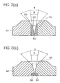
- Figs. 3(a)-(c) are cross-sectional views showing the sizing dies associated with different embodiments of the invention.
-
- The following description of preferred embodiments of the invention is offered for purposes of illustration of the principles of this invention and it is not intended to be limiting.
- Fig. 1 is a schematic illustration showing the basic structure of a fiber forming and coating line 10. The line 10 includes an optical
fiber forming device 12, a fiberdiameter measurement device 14, afiber coating device 16, aprimary coating applicator 18, a primary coating curing device, 20, asecondary coating applicator 22, a secondarycoating curing device 24, a coated fiberdiameter measurement device 26 and acapstan 28.Optical fiber 30 is drawn from thefiber forming device 12 and passes through the fiberdiameter measurement device 14 which measures the diameter of theoptical fiber 30. Thefiber 30 then passes throughprimary coating applicator 18 where it is coated with a primary layer. The primary coating is then cured by the primarycoating curing device 20 and thefiber 30 is then passed through thesecondary coating applicator 22 where a secondary coating layer is applied. The secondary coating is then cured by the secondarycoating curing device 24, after which the final diameter of the coated optical fiber is measured by themeasurement device 26. Theoptical fiber 30 is then wound aroundcapstan 28 and onto a spooling device (not shown). - The present invention is directed to the design of the
primary coating applicator 18, illustrated in Fig. 2. FIG. 2 is a cross-sectional view ofcoating applicator 18. Thecoating applicator 18 includes a cylindrically-shaped housing 32 having longitudinally-spaced,coaxial bores housing 32 may be formed of steel or stainless steel or any machinable metal or the like. Bores 36 and 38 meet to form an inwardly projectingshoulder 40 upon which sizing die 42 is seated. Immediately above sizing die 42 is a cylindrical,flow distribution area 44 to which the coating is supplied viainlets 46. Bores 34 and 36 also meet to form ashoulder 48 upon which a guide die 50 is seated. The guide die 50 is conventional and includes a taperedlongitudinal aperture 52 followed by a cylindrical aperture corresponding to a guide dieorifice 54. The presence ofguide die orifice 54 facilitates the initial feeding offiber 30 through the coater. It causes an inserted fiber to be centered so that it will readily pass through the coater without becoming snagged. Theorifice 54 is sufficiently large that the fiber does not come into contact with it during the fiber drawing and coating operation. - The
sizing die 42 has abore 56 in which adiamond insert 58 is located. With reference to Figs. 3(a) and 3(c), there are three alternative designs for the sizing die. Referring to Fig. 3(a), according to a first embodiment, the inlet end thesizing die 42 includes a firsttapered aperture 60 having a wide opening defined by a relatively wide angle (of approximately 90°). In contrast, thediamond insert 58 includes a secondtapered aperture 62 having a relatively narrow opening defined by an angle β (of approximately 12°) followed by acylindrical land opening 64. Thus, in this embodiment, the heatconductive diamond insert 58 includes both the taperedregion 62 and theland region 64 of the sizing die. Thus, wall continuity and smoothness is ensured in all locations that are contacted by the high speed and high shear rate coating flow. Flow eddies are thus avoided. - The extension of the insert to include part of the tapered
region 62 of the die is beneficial but not essential for heat transfer. For example, referring to Fig. 3(b), according to a second embodiment, the sizing die 42 includes a single taperedopening 66 that is initially defined by a relative wide angle (approximately 90°) but tapers down to a smaller angle β (approximately 12°). Theinsert 58 is located on the downstream side of the sizing die 42 and includes just aland region 68 having a sizingorifice 70. The size oforifice 70 is determined by various parameters including the diameter of the optical fiber to be coated, the thickness of the coating and the particular coating material employed. - Thus, in this particular embodiment the heat-conductive insert includes only the cylindrical land region of the sizing die. The sizing die 42 is made of a cast metal, such as cast iron, or a similar machinable material. This design is sufficient to allow dissipation of most of the heat produced by viscous losses as these losses occur mainly over the inner wall of the
land region 68 of thedie insert 58. Special care must be given to avoid discontinuities of the inner wall at the up stream side of theinsert 58. Turbulence in the coating flow may be otherwise initiated, as this limit is located in a region of extreme speed and shear rate in the coating flow. Provided successful manufacturing, this embodiment may be cheaper than state of the art Tungsten Carbide dies. - Referring to Fig. 3(c), a third, altogether different embodiment of the invention could be realized by replacing the heat
conductive insert 58 with a sufficientlythick layer 70 of heat conductive material like pyrolithic diamond over part or the entire inner wall of the sizing die. - According to an important aspect of the invention, the
die insert 58 in each embodiment is made of a material which has a high thermal conductivity, greater than 1 W/cm*K. Examples of such a material include all varieties of diamond, natural or synthetic (having a thermal conductivity in the range of 5 to 20 W/cm*K) or isotopically pure C12 diamond (with a conductivity of 50 W/cm*K). Another suitable but less performant material could be Silicon Carbide (with a conductivity in the range of 1 to 1.3 W/cm*K at room temperature). - This is in contrast to conventional coating die inserts having a thermal conductivity of only 0.15 W/cm*K. It has been discovered that the high conductivity of the insert minimizes the differences or imbalances between the inner wall temperatures of the die so that the temperature of the inner wall is generally uniform around the circumference of the die insert. Therefore, the effects discussed above with regard to the generation of de-centering forces due to the variation in wall temperature is substantially reduced or even eliminated. In particular, whereas localized heat generated due to a non-uniform viscosity profile is relatively high in a die having a low thermal conductivity due to poor heat dissipation, the heat generated in a die having a high conductivity is quickly dissipated such that localized heating is substantially reduced. Therefore, even if one side of the fiber begins to be offset toward the adjacent wall of the die, there is a minimal amount of heat remaining in the liquid on that side of the fiber. As a result, the pressure profile around the fiber remains generally uniform in the land region so that the fiber is not drawn to one side.
- Thus, the present invention provides a much simpler solution that the prior art systems discussed above in which the ability to monitor the concentricity of the coating on-line is required.
- Specifically, it has been confirmed by numerical simulation that a die insert having a high thermal conductivity is advantageous in rapidly dissipating heat generated by viscous heating (the result of the conversion of mechanical to thermal energy via fluid friction). Viscous heating tends to occur most where shear rate is highest in the coating flow. In the land region of the sizing die, high shear rate and subsequent heating are highest over the inner wall of the sizing die. This heat can be extracted easily if the heat conductivity of the die is sufficient.
- In addition, simulations show that shear rate and viscous dissipation on opposite sides of the fiber become unbalanced if the fiber is off-centered with respect to the sizing-die, a situation which often occurs in actual fiber manufacturing. This initial unbalance induces subsequent unbalances between temperatures, coating viscosities, and pressures on opposite sides of the fiber unless die heat conductivity is sufficiently high to both evacuate heat radially and to conduct it around the inner wall of the die to equalize temperatures as best as possible. Results of simulation show that in case of use of a high conductivity insert substantial centering force is generated in the tapered region of the die pulling back the off-centered fiber. To the contrary, if temperatures on either sides of the fiber are left unbalanced and uncontrolled, flow rates are likely to become in turn unbalanced, especially in the land region, and the global centering force is mitigated producing a loss of coating concentricity.
Claims (13)
- An apparatus for coating an optical fiber, comprising:wherein said sizing-die includes a housing (42) and an insert (58), and said insert defines at least said land region of said bore and has a thermal conductivity greater than 1 W/cm*K.a sizing die having a bore with a tapered region (60, 62) and an adjacent land region (64, 68) to which a curable coating material is supplied,means for curing said coating material,
- The apparatus of claim 1, wherein said insert is a diamond insert.
- The apparatus of claim 1 or 2, wherein said insert (58) defines both said tapered region (64) and said land region (68) of the bore.
- The apparatus of claim 3, wherein said land region is immediately downstream of said tapered region.
- The apparatus of one of claims 1 to 4, wherein said tapered region tapers from a relatively wide opening (66) at an entrance portion of said sizing die to a relatively narrow opening downstream thereof.
- The apparatus of one of claims 1 to 5, wherein said insert is a coating (70) applied to said housing (42).
- The apparatus of one of claims 1 and 3 to 6, wherein said insert is silicon carbide.
- A sizing-die for coating an optical fiber with a coating material, comprising:said housing and said die insert together defining a bore having a tapered region (60, 62) and a land region (64, 68) disposed downstream of said tapered region, wherein said die insert has a thermal conductivity greater than 1 W/cm*K such that heat generated during application of said coating is extracted efficiently from said insert.a housing (42) ; anda die insert (58) positioned in said housing,
- The sizing-die of claim 8, wherein said die insert is a diamond insert.
- The sizing-die of claim 8 or 9, wherein said die insert defines at least said land region (64, 68) of said bore.
- The sizing-die of claim 10, wherein said die insert includes a tapered entrance portion (62) upstream of said land region.
- The sizing-die of claim 8 or 10, wherein said die insert (70) is a coating applied to said housing.
- The sizing-die of claim 8, wherein said die insert is silicon carbide.
Applications Claiming Priority (2)
| Application Number | Priority Date | Filing Date | Title |
|---|---|---|---|
| US390022 | 1999-09-03 | ||
| US09/390,022 US6537377B1 (en) | 1999-09-03 | 1999-09-03 | Apparatus for coating optical fibers |
Publications (2)
| Publication Number | Publication Date |
|---|---|
| EP1081109A1 true EP1081109A1 (en) | 2001-03-07 |
| EP1081109B1 EP1081109B1 (en) | 2004-11-03 |
Family
ID=23540727
Family Applications (1)
| Application Number | Title | Priority Date | Filing Date |
|---|---|---|---|
| EP00402283A Expired - Lifetime EP1081109B1 (en) | 1999-09-03 | 2000-08-11 | Apparatus for coating optical fibers |
Country Status (4)
| Country | Link |
|---|---|
| US (1) | US6537377B1 (en) |
| EP (1) | EP1081109B1 (en) |
| JP (1) | JP4815045B2 (en) |
| DE (1) | DE60015462T2 (en) |
Families Citing this family (4)
| Publication number | Priority date | Publication date | Assignee | Title |
|---|---|---|---|---|
| US7165119B2 (en) * | 2003-10-14 | 2007-01-16 | America Online, Inc. | Search enhancement system and method having rankings, explicitly specified by the user, based upon applicability and validity of search parameters in regard to a subject matter |
| US7892460B1 (en) * | 2009-02-17 | 2011-02-22 | Paradigm Optics | Enclosed drawing method |
| CN111936443A (en) * | 2018-03-22 | 2020-11-13 | 住友电气工业株式会社 | Method and apparatus for manufacturing optical fiber |
| CN114392888A (en) * | 2021-06-07 | 2022-04-26 | 东莞庆泰电线电缆有限公司 | Coating process and coating system for cable and prepared cable |
Citations (6)
| Publication number | Priority date | Publication date | Assignee | Title |
|---|---|---|---|---|
| GB1371318A (en) * | 1973-03-29 | 1974-10-23 | Standard Telephones Cables Ltd | Coating glass optical fibre |
| US4531959A (en) * | 1984-10-04 | 1985-07-30 | Corning Glass Works | Method and apparatus for coating optical fibers |
| GB2170738A (en) * | 1985-02-08 | 1986-08-13 | Stc Plc | Coating optical fibres |
| US5151306A (en) * | 1990-11-26 | 1992-09-29 | At&T Bell Laboratories | Methods of coating elongated strand material |
| WO1997020237A2 (en) * | 1995-11-13 | 1997-06-05 | Corning Incorporated | Method and apparatus for coating optical fibers |
| DE19801700A1 (en) * | 1998-01-17 | 1999-07-22 | Cit Alcatel | Fiber coating equipment, especially for optical glass fiber |
Family Cites Families (13)
| Publication number | Priority date | Publication date | Assignee | Title |
|---|---|---|---|---|
| US3944459A (en) * | 1974-12-04 | 1976-03-16 | Dow Corning Corporation | Method and apparatus for applying reinforced insulation to a conductor |
| US4046103A (en) | 1976-03-29 | 1977-09-06 | Owens-Corning Fiberglas Corporation | Impregnating die |
| US4253731A (en) | 1979-04-09 | 1981-03-03 | Honeywell Inc. | Infrared fiber of AgCl clad AgBr and method of fabrication |
| US4514205A (en) | 1981-11-05 | 1985-04-30 | Corning Glass Works | Fiber cooling apparatus |
| US4678274A (en) | 1983-12-27 | 1987-07-07 | Fuller Research Corporation | Low loss cladded optical fibers from halides and process for making same |
| US4649856A (en) | 1984-04-06 | 1987-03-17 | Northern Telecom Limited | Production of insulated electrical conductors |
| US4594088A (en) | 1985-05-28 | 1986-06-10 | At&T Technologies, Inc. | Method and apparatus for making, coating and cooling lightguide fiber |
| US5186870A (en) | 1987-12-17 | 1993-02-16 | Fuller Research Corporation | Process for fabricating an IR transmitting optical fiber |
| US4955689A (en) | 1987-12-17 | 1990-09-11 | Fuller Research Corporation | IR transmitting optical fiber |
| US5043001A (en) | 1990-05-29 | 1991-08-27 | Corning Incorporated | Method and apparatus for fiber cooling |
| GB9100631D0 (en) | 1991-01-11 | 1991-02-27 | De Beers Ind Diamond | Wire drawing dies |
| US5366527A (en) | 1993-04-05 | 1994-11-22 | Corning Incorporated | Method and apparatus for coating optical waveguide fibers |
| JP2922208B2 (en) * | 1998-10-28 | 1999-07-19 | 川鉄建材株式会社 | Resin coater |
-
1999
- 1999-09-03 US US09/390,022 patent/US6537377B1/en not_active Expired - Lifetime
-
2000
- 2000-08-11 DE DE60015462T patent/DE60015462T2/en not_active Expired - Lifetime
- 2000-08-11 EP EP00402283A patent/EP1081109B1/en not_active Expired - Lifetime
- 2000-08-21 JP JP2000249268A patent/JP4815045B2/en not_active Expired - Fee Related
Patent Citations (6)
| Publication number | Priority date | Publication date | Assignee | Title |
|---|---|---|---|---|
| GB1371318A (en) * | 1973-03-29 | 1974-10-23 | Standard Telephones Cables Ltd | Coating glass optical fibre |
| US4531959A (en) * | 1984-10-04 | 1985-07-30 | Corning Glass Works | Method and apparatus for coating optical fibers |
| GB2170738A (en) * | 1985-02-08 | 1986-08-13 | Stc Plc | Coating optical fibres |
| US5151306A (en) * | 1990-11-26 | 1992-09-29 | At&T Bell Laboratories | Methods of coating elongated strand material |
| WO1997020237A2 (en) * | 1995-11-13 | 1997-06-05 | Corning Incorporated | Method and apparatus for coating optical fibers |
| DE19801700A1 (en) * | 1998-01-17 | 1999-07-22 | Cit Alcatel | Fiber coating equipment, especially for optical glass fiber |
Also Published As
| Publication number | Publication date |
|---|---|
| JP2001114536A (en) | 2001-04-24 |
| DE60015462T2 (en) | 2005-10-27 |
| US6537377B1 (en) | 2003-03-25 |
| DE60015462D1 (en) | 2004-12-09 |
| EP1081109B1 (en) | 2004-11-03 |
| JP4815045B2 (en) | 2011-11-16 |
Similar Documents
| Publication | Publication Date | Title |
|---|---|---|
| AU700985B2 (en) | Method and apparatus for coating optical fibers | |
| US4531959A (en) | Method and apparatus for coating optical fibers | |
| AU681863B2 (en) | Method and apparatus for coating optical waveguide fibers | |
| JPH0361622B2 (en) | ||
| US6958096B2 (en) | Systems and methods for coating optical fiber | |
| US4374161A (en) | Pressure coating of fibers | |
| JPH0655989B2 (en) | Fiber coating equipment | |
| US6537377B1 (en) | Apparatus for coating optical fibers | |
| US4480898A (en) | Fibers with multiple coatings | |
| WO1983000451A1 (en) | Methods of and apparatus for coating lightguide fiber | |
| FI104295B (en) | Resin coating device for optical fiber | |
| JP2005162598A (en) | Device and method of producing a plurality of glass fibers | |
| US6991679B2 (en) | Multiple feed applicator assembly for coating optical fibers | |
| KR20010024306A (en) | Draw constant downfeed process | |
| US6030664A (en) | Biconic coating die for making coated optical fibers | |
| US5358570A (en) | Crosshead apparatus for jacketing wire core | |
| US11524920B2 (en) | Optical fiber coating die with reduced wetted length | |
| US4579079A (en) | Apparatus for use in coating an elongate filament | |
| CA1177614A (en) | Method and apparatus for use in coating an elongate filament | |
| JP2023128454A (en) | Optical fiber manufacturing method and optical fiber manufacturing device | |
| MXPA98002058A (en) | Method and apparatus for supplying a contrachap glass current | |
| HK1003538B (en) | Method and apparatus for coating optical waveguide fibers | |
| JPH01145352A (en) | Production of optical fiber core covered with metal and dice therein | |
| JPH02279539A (en) | Device for coating optical fiber |
Legal Events
| Date | Code | Title | Description |
|---|---|---|---|
| PUAI | Public reference made under article 153(3) epc to a published international application that has entered the european phase |
Free format text: ORIGINAL CODE: 0009012 |
|
| AK | Designated contracting states |
Kind code of ref document: A1 Designated state(s): DE FR GB IT NL |
|
| AX | Request for extension of the european patent |
Free format text: AL;LT;LV;MK;RO;SI |
|
| 17P | Request for examination filed |
Effective date: 20010811 |
|
| AKX | Designation fees paid |
Free format text: DE FR GB IT NL |
|
| 17Q | First examination report despatched |
Effective date: 20020920 |
|
| GRAP | Despatch of communication of intention to grant a patent |
Free format text: ORIGINAL CODE: EPIDOSNIGR1 |
|
| GRAS | Grant fee paid |
Free format text: ORIGINAL CODE: EPIDOSNIGR3 |
|
| GRAA | (expected) grant |
Free format text: ORIGINAL CODE: 0009210 |
|
| AK | Designated contracting states |
Kind code of ref document: B1 Designated state(s): DE FR GB IT NL |
|
| REG | Reference to a national code |
Ref country code: GB Ref legal event code: FG4D |
|
| REF | Corresponds to: |
Ref document number: 60015462 Country of ref document: DE Date of ref document: 20041209 Kind code of ref document: P |
|
| RAP2 | Party data changed (patent owner data changed or rights of a patent transferred) |
Owner name: DRAKA COMTEQ B.V. |
|
| NLT2 | Nl: modifications (of names), taken from the european patent patent bulletin |
Owner name: DRAKA COMTEQ B.V. |
|
| PLBE | No opposition filed within time limit |
Free format text: ORIGINAL CODE: 0009261 |
|
| STAA | Information on the status of an ep patent application or granted ep patent |
Free format text: STATUS: NO OPPOSITION FILED WITHIN TIME LIMIT |
|
| 26N | No opposition filed |
Effective date: 20050804 |
|
| ET | Fr: translation filed | ||
| PGFP | Annual fee paid to national office [announced via postgrant information from national office to epo] |
Ref country code: DE Payment date: 20140827 Year of fee payment: 15 Ref country code: NL Payment date: 20140826 Year of fee payment: 15 |
|
| PGFP | Annual fee paid to national office [announced via postgrant information from national office to epo] |
Ref country code: GB Payment date: 20140827 Year of fee payment: 15 Ref country code: FR Payment date: 20140818 Year of fee payment: 15 |
|
| PGFP | Annual fee paid to national office [announced via postgrant information from national office to epo] |
Ref country code: IT Payment date: 20140827 Year of fee payment: 15 |
|
| REG | Reference to a national code |
Ref country code: DE Ref legal event code: R119 Ref document number: 60015462 Country of ref document: DE |
|
| GBPC | Gb: european patent ceased through non-payment of renewal fee |
Effective date: 20150811 |
|
| PG25 | Lapsed in a contracting state [announced via postgrant information from national office to epo] |
Ref country code: IT Free format text: LAPSE BECAUSE OF NON-PAYMENT OF DUE FEES Effective date: 20150811 |
|
| REG | Reference to a national code |
Ref country code: NL Ref legal event code: MM Effective date: 20150901 |
|
| REG | Reference to a national code |
Ref country code: FR Ref legal event code: ST Effective date: 20160429 |
|
| PG25 | Lapsed in a contracting state [announced via postgrant information from national office to epo] |
Ref country code: NL Free format text: LAPSE BECAUSE OF NON-PAYMENT OF DUE FEES Effective date: 20150901 |
|
| PG25 | Lapsed in a contracting state [announced via postgrant information from national office to epo] |
Ref country code: GB Free format text: LAPSE BECAUSE OF NON-PAYMENT OF DUE FEES Effective date: 20150811 Ref country code: DE Free format text: LAPSE BECAUSE OF NON-PAYMENT OF DUE FEES Effective date: 20160301 |
|
| PG25 | Lapsed in a contracting state [announced via postgrant information from national office to epo] |
Ref country code: FR Free format text: LAPSE BECAUSE OF NON-PAYMENT OF DUE FEES Effective date: 20150831 |