EP1080998A2 - Method of making a hidden tear seam in a vehicle body panel - Google Patents
Method of making a hidden tear seam in a vehicle body panel Download PDFInfo
- Publication number
- EP1080998A2 EP1080998A2 EP00113250A EP00113250A EP1080998A2 EP 1080998 A2 EP1080998 A2 EP 1080998A2 EP 00113250 A EP00113250 A EP 00113250A EP 00113250 A EP00113250 A EP 00113250A EP 1080998 A2 EP1080998 A2 EP 1080998A2
- Authority
- EP
- European Patent Office
- Prior art keywords
- mold
- skin
- tear seam
- sprayed
- mold surface
- Prior art date
- Legal status (The legal status is an assumption and is not a legal conclusion. Google has not performed a legal analysis and makes no representation as to the accuracy of the status listed.)
- Withdrawn
Links
- 238000004519 manufacturing process Methods 0.000 title claims abstract description 5
- 239000000463 material Substances 0.000 claims abstract description 32
- 239000012815 thermoplastic material Substances 0.000 claims abstract description 8
- 230000005484 gravity Effects 0.000 claims abstract description 4
- 229920001169 thermoplastic Polymers 0.000 claims abstract description 3
- 239000004416 thermosoftening plastic Substances 0.000 claims abstract description 3
- 239000007921 spray Substances 0.000 claims description 13
- 238000000034 method Methods 0.000 claims description 8
- 229920003023 plastic Polymers 0.000 claims description 5
- 239000004033 plastic Substances 0.000 claims description 5
- 238000005507 spraying Methods 0.000 claims description 4
- 229920002635 polyurethane Polymers 0.000 abstract description 3
- 239000004814 polyurethane Substances 0.000 abstract description 3
- 125000000391 vinyl group Chemical group [H]C([*])=C([H])[H] 0.000 description 28
- 229920002554 vinyl polymer Polymers 0.000 description 28
- 239000000758 substrate Substances 0.000 description 18
- 239000006260 foam Substances 0.000 description 15
- JOYRKODLDBILNP-UHFFFAOYSA-N Ethyl urethane Chemical compound CCOC(N)=O JOYRKODLDBILNP-UHFFFAOYSA-N 0.000 description 14
- 238000007373 indentation Methods 0.000 description 5
- 238000004378 air conditioning Methods 0.000 description 3
- 229920005955 Elastolit® Polymers 0.000 description 2
- 238000010438 heat treatment Methods 0.000 description 2
- 239000002991 molded plastic Substances 0.000 description 2
- 238000000465 moulding Methods 0.000 description 2
- 229910000831 Steel Inorganic materials 0.000 description 1
- 125000003118 aryl group Chemical group 0.000 description 1
- 239000011230 binding agent Substances 0.000 description 1
- 239000013043 chemical agent Substances 0.000 description 1
- 238000010276 construction Methods 0.000 description 1
- 238000001816 cooling Methods 0.000 description 1
- 238000009472 formulation Methods 0.000 description 1
- 238000013467 fragmentation Methods 0.000 description 1
- 238000006062 fragmentation reaction Methods 0.000 description 1
- 238000009434 installation Methods 0.000 description 1
- 239000011344 liquid material Substances 0.000 description 1
- 239000000203 mixture Substances 0.000 description 1
- 230000001737 promoting effect Effects 0.000 description 1
- 239000011347 resin Substances 0.000 description 1
- 229920005989 resin Polymers 0.000 description 1
- 239000010959 steel Substances 0.000 description 1
- 239000000126 substance Substances 0.000 description 1
- 238000004381 surface treatment Methods 0.000 description 1
Images


Classifications
-
- B—PERFORMING OPERATIONS; TRANSPORTING
- B60—VEHICLES IN GENERAL
- B60R—VEHICLES, VEHICLE FITTINGS, OR VEHICLE PARTS, NOT OTHERWISE PROVIDED FOR
- B60R21/00—Arrangements or fittings on vehicles for protecting or preventing injuries to occupants or pedestrians in case of accidents or other traffic risks
- B60R21/02—Occupant safety arrangements or fittings, e.g. crash pads
- B60R21/16—Inflatable occupant restraints or confinements designed to inflate upon impact or impending impact, e.g. air bags
- B60R21/20—Arrangements for storing inflatable members in their non-use or deflated condition; Arrangement or mounting of air bag modules or components
- B60R21/215—Arrangements for storing inflatable members in their non-use or deflated condition; Arrangement or mounting of air bag modules or components characterised by the covers for the inflatable member
- B60R21/2165—Arrangements for storing inflatable members in their non-use or deflated condition; Arrangement or mounting of air bag modules or components characterised by the covers for the inflatable member characterised by a tear line for defining a deployment opening
-
- B—PERFORMING OPERATIONS; TRANSPORTING
- B29—WORKING OF PLASTICS; WORKING OF SUBSTANCES IN A PLASTIC STATE IN GENERAL
- B29C—SHAPING OR JOINING OF PLASTICS; SHAPING OF MATERIAL IN A PLASTIC STATE, NOT OTHERWISE PROVIDED FOR; AFTER-TREATMENT OF THE SHAPED PRODUCTS, e.g. REPAIRING
- B29C37/00—Component parts, details, accessories or auxiliary operations, not covered by group B29C33/00 or B29C35/00
- B29C37/0053—Moulding articles characterised by the shape of the surface, e.g. ribs, high polish
- B29C37/0057—Moulding single grooves or ribs, e.g. tear lines
-
- B—PERFORMING OPERATIONS; TRANSPORTING
- B29—WORKING OF PLASTICS; WORKING OF SUBSTANCES IN A PLASTIC STATE IN GENERAL
- B29C—SHAPING OR JOINING OF PLASTICS; SHAPING OF MATERIAL IN A PLASTIC STATE, NOT OTHERWISE PROVIDED FOR; AFTER-TREATMENT OF THE SHAPED PRODUCTS, e.g. REPAIRING
- B29C41/00—Shaping by coating a mould, core or other substrate, i.e. by depositing material and stripping-off the shaped article; Apparatus therefor
- B29C41/34—Component parts, details or accessories; Auxiliary operations
- B29C41/36—Feeding the material on to the mould, core or other substrate
-
- B—PERFORMING OPERATIONS; TRANSPORTING
- B29—WORKING OF PLASTICS; WORKING OF SUBSTANCES IN A PLASTIC STATE IN GENERAL
- B29K—INDEXING SCHEME ASSOCIATED WITH SUBCLASSES B29B, B29C OR B29D, RELATING TO MOULDING MATERIALS OR TO MATERIALS FOR MOULDS, REINFORCEMENTS, FILLERS OR PREFORMED PARTS, e.g. INSERTS
- B29K2075/00—Use of PU, i.e. polyureas or polyurethanes or derivatives thereof, as moulding material
-
- B—PERFORMING OPERATIONS; TRANSPORTING
- B29—WORKING OF PLASTICS; WORKING OF SUBSTANCES IN A PLASTIC STATE IN GENERAL
- B29L—INDEXING SCHEME ASSOCIATED WITH SUBCLASS B29C, RELATING TO PARTICULAR ARTICLES
- B29L2031/00—Other particular articles
- B29L2031/30—Vehicles, e.g. ships or aircraft, or body parts thereof
- B29L2031/3005—Body finishings
- B29L2031/3008—Instrument panels
-
- B—PERFORMING OPERATIONS; TRANSPORTING
- B60—VEHICLES IN GENERAL
- B60R—VEHICLES, VEHICLE FITTINGS, OR VEHICLE PARTS, NOT OTHERWISE PROVIDED FOR
- B60R21/00—Arrangements or fittings on vehicles for protecting or preventing injuries to occupants or pedestrians in case of accidents or other traffic risks
- B60R21/02—Occupant safety arrangements or fittings, e.g. crash pads
- B60R21/16—Inflatable occupant restraints or confinements designed to inflate upon impact or impending impact, e.g. air bags
- B60R21/20—Arrangements for storing inflatable members in their non-use or deflated condition; Arrangement or mounting of air bag modules or components
- B60R21/205—Arrangements for storing inflatable members in their non-use or deflated condition; Arrangement or mounting of air bag modules or components in dashboards
Definitions
- the invention relates to a method of making a hidden tear seam in a vehicle body panel to enable deployment of an airbag via tearing of the panel.
- the vehicle body panel typically includes a rigid substrate panel, a layer of padding material, and a vinyl skin.
- the substrate material includes an opening which registers with the air bag.
- a door panel is hinged within the opening and the vinyl material bridges across the opening and the door panel.
- the prior art is known to promote tearing of the vinyl upon deployment of the air bag by molding the vinyl to provide a reduced cross section thickness of the vinyl skin at the desired location of the tear seam. It has also been proposed to score the vinyl skin using a laser or other cutting technique to weaken the skin and thereby provide a tear seam.
- the present invention provides a new and improved process for providing a hidden tear seam in a vinyl skin for an air bag mounted on the steering wheel, on the instrument panel, in the door panel, or elsewhere in the vehicle body.
- a method of making a thermoplastic skin comprises the steps of providing a mold having a mold surface with first and second mold surface portions which intersect at a sharp corner coincident with the desired location of the tear seam in the molded skin.
- the mold is oriented with one of the first and second mold surface portions oriented in a generally horizontally orientation and the other of the mold surface portions oriented in a generally vertical orientation.
- a thermoplastic material such as polyurethane is sprayed onto the mold surface and the curing of the sprayed material is controlled to permit gravity to induce flow of the sprayed material down the vertical surface of the mold at the sharp corner and thereby provide a cured skin which is of significantly lessened thickness at the corner than at other regions of the skin. Accordingly, the reduced thickness of thermoplastic material at the sharp corner defines the tear seam at which the skin material will tear upon deployment of an air bag against the skin.
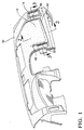
- a motor vehicle instrument panel cover 10 is shown for installation in a motor vehicle body to conceal and enclose such components as the instrument cluster, radio, and heating ventilating and air conditioning systems.
- the instrument panel cover 10 has a hidden air bag door 12, the edges of the door being generally located behind the indentation 14 in the surface or cover 10.
- FIG 2 shows the instrument panel cover 10 of Figure 1 installed in the vehicle.
- the instrument panel cover 10 includes a rigid molded plastic substrate 18, a layer of urethane foam 20 and a vinyl skin 22.
- the instrument panel cover 10 is manufactured by placing the pre-molded substrate 18 and the pre-molded vinyl skin 22 in a mold and then injecting urethane foam into space between the substrate 18 and vinyl skin 22.
- the skin 22 may be placed on one half of the mold, the substrate 18 placed on the other half of the mold, and then the uncured foam poured into the mold before the mold is closed.
- the urethane foam 20 adheres to both the substrate 18 and the vinyl skin 22 and provides a layer of cushioning therebetween.
- the instrument panel cover 10 encloses an air conditioning duct 24 and an air bag assembly 26.
- Air bag assembly 26 includes a conventional inflator 28 and a folded up air bag 30.
- the substrate 18 of the instrument panel cover has a generally rectangular opening 32 defined in part by a top wall 34 and a bottom wall 36. This opening 32 of the substrate 18 registers with the air bag assembly 26.
- An air bag door panel 40 of stamped steel or molded plastic construction has a top edge 42 which is suitably hinged to the substrate member 18 adjacent to the top wall 32 of the air bag opening 40 by suitable hinges which are not shown in the drawing.
- the bottom edge of the door panel seats on a flange 43 of the substrate 18.
- the layer of urethane foam 20 adheres the vinyl skin 22 to the hinged door panel 40.
- the air bag 30 Upon actuation of the air bag inflator 28, the air bag 30 is deployed against the backside of the door panel 40, causing the air bag door 40 to hinge upwardly and thereby permit deployment of the air bag into the occupant compartment of the vehicle. It will be understood and appreciated that the upward hinging of the door panel 40 will require tearing of the vinyl skin 22 along the path of the tear seam indentation 14 shown in Figure 1.
- the present invention provides a new and improved method for making a vinyl skin to provide a hidden air bag seam.
- the lower edge of the hidden tear seam indentation 14 is provided at a shoulder 44 of the vinyl skin 22.
- the right hand portion of the hidden tear seam 14 is provided at a shoulder 46 and the left hand portion of the hidden tear seam 14 is provided at a shoulder 48 which melds into the cutout 50 for an air conditioning vent, not shown.
- a mold 52 is provided for molding the vinyl skin 52 and forming therein the hidden tear seam 14.
- the mold 52 has a mold surface 54 upon which a spray head 56 will deposit a curable molten thermoplastic material, such as spray urethane.
- a suitable material spray urethane material is Elastolit® M50555R Resin/Elastolit® M5055ST Isocyanase Spray Aromatic Urethane System by BASF Corporation.
- the spray gun may be operated by a robot.
- the mold surface 54 is shaped and suitably grained to provide the outer surface of the vinyl skin 22.
- the instrument panel designer has intentionally shaped the skin 22 to have mold surface portions which intersect at a sharp corner coincident with the desired location of the tear seam 14 indentation.
- the right hand portion 46 of Figure 3 will be defined by a raised rib structure 56 on the mold, while the left hand portion 48 is defined by a shoulder 58 of the mold.
- Figure 6 is an enlarged view of the rib 56 and shows in particular that the rib 56 has a sharp corner 60 and a sharp corner 62.
- the sharp corner 60 occurs at the intersection of a first mold surface portion 64 which is oriented generally vertically and a second mold surface portion 66 which is oriented generally horizontal.
- the sharp corner 62 is defined at the intersection of the second mold surface portion 66 and another mold surface portion 68 which is also oriented generally vertically.
- Figure 6 shows the sprayed build up of the urethane material on the mold surface 54.
- the viscosity of the sprayed urethane material enables and causes the sprayed urethane material to slump under the influence of gravity such that the material will flow away from the corners 60 and 62 and down the vertically oriented wall surface portions 64 and 68.
- the nominal intended thickness for the vinyl skin may be, for example, 1.0 millimeter
- the flow of the liquid material away from the corners will result in a thickness at the corners of .2 mm while the thickness further down the vertical wall may build up to perhaps 1.5 mm.
- the extent to which the uncured material will flow and slump, and accordingly the thickness of the vinyl skin 22 at the corners 60 and 62 can be controlled by controlling variables such as sharpness of the corner, the formulation of the plastic material, the viscosity of plastic material, the number of passes made by the sprayer, and/or cure rate of the plastic material, as determined, for example, by heating or cooling of the mold.
- the shoulder 58 of the mold is oriented in the vertical direction and intersects with a horizontal mold surface portion 72 to define a sharp corner 74.
- the sprayed urethane material flows and slumps to provide a reduced thickness at sharp corner 74 to define the left hand side 48 of the tear seam indentation 14.
- the skin 22 is removed from the mold 54 of Figure 5 and then subsequently adhered to the substrate 18 by the urethane foam 20 as was previously described herein.
- FIG 8 there is shown an enlarged fragmentary view of the right hand portion of the hidden tear seam 46.
- the air bag is being deployed to forcibly load the air bag door 40 and cause a tearing of the foam 20 and the vinyl skin 22.
- Figure 8 shows the door 40 having begun its opening movement such that the skin 22 has been tensioned and torn at the right hand tear seam 46.
- this tearing can occur at either the reduced thickness provided at corner 60 of the mold shown in Figure 6, or at the reduced thickness provided at the corner 62 of the mold, Simultaneously, in a similar fashion, tearing will initiate at the lower portion 44 and left hand portion 48 of the hidden tear seam.
- the airbag door 40 is larger than the airbag opening and accordingly overlaps onto the retainer 18 by a distance designated "a”.
- the tear seam is spaced away from the edge of the airbag door 40 by a distance designated "b".
- tearing of the skin 22 to permit opening of the airbag door 40 is accompanied by tearing of the layer of foam 20.
- the tearing of the foam 20 at or adjacent to the tear seam of the vinyl skin 22 may be enhanced by surface treatments provided on various regions of the face of the substrate 18.
- a chemical agent may be provided on surface substrate 80 of the retainer 80 to permit the adjacent region of the foam 20 to easily pull away from the substrate 80.
- Other surfaces of the substrate 18, such as the surface portion designated at 82 may be molded in a roughened condition, or treated with a suitable chemical binding agent, to enhance adhesion of the foam 20 to the retainer 18 at the surface portion 82
- a convenient and no cost method for promoting adhesion between the skin 22 and foam 20 may be obtained by controlling the sprayer 56.
- the sprayer 56 it has been discovered that by first spraying the urethane material onto the mold 54 in the region on the end of the mold adjacent the passenger side airbag, and then proceeding to spray the material at the center of the instrument panel and then the driver side of the instrument panel, the over spray which naturally occurs during the spraying of the material at the center and left hand end of the mold will cause droplets of spray to be deposited on the passenger side end of the skin 22, thereby providing a roughened surface texture of the skin 22 so that when the foam 20 is cured against the skin 22 an enhanced adhesion performance is provided.
- the instrument panel skin may be manufactured by suspending the mold 56 upside down and then spraying the polyurethane material upwardly unto the mold. Accordingly, as seen in Figure 9, the viscous nature of the uncured material will allow the material to flow and slump so that a thinned cross section is provided at or adjacent corner 82 of the mold. Accordingly, the thin cross section at 80 will provide the hidden tear seam of this invention.
- the invention provides a new and improved method for making a hidden tear seam in a vehicle body panel.
Landscapes
- Engineering & Computer Science (AREA)
- Mechanical Engineering (AREA)
- Air Bags (AREA)
- Casting Or Compression Moulding Of Plastics Or The Like (AREA)
Abstract
Description
Claims (4)
- Method of making a thermoplastic skin for a vehicle body panel and having a hidden tear seam providing a door through which an air bag may deploy by tearing the skin, comprising the steps of:designing the skin to have first and second skin surfaces which intersect at a sharp corner coincident with the location of the tear seam;providing a mold having a mold surface with first and second mold surface portions which intersect at a corner coincident with the location of the tear seam;orienting the mold with one of the first and second mold surface portions in a generally horizontal orientation and the other of the mold surface portions oriented in a generally vertical orientation;spraying curable thermoplastic material onto the mold surface,and controlling the curing of the sprayed material so that gravity will induce flow of the material down the vertical surface of the mold at the corner and thereby provide a cured skin material which is of significantly lessened thickness at the corner than at other regions of the skin whereby an integral hidden tear seam is provided for tearing upon deployment of an air bag against the skin.
- A method of Claim 1 further comprising the thermal plastic skin having a first end region in which the hidden tear seam is provided and another end portion region distant from the portion having a hidden tear seam and in which the curable thermal plastic material is first sprayed upon the region having the hidden tear seam and then subsequently the material is sprayed onto another other region of the mold so that the over spray which occurs when another end portion is sprayed fall upon the first end portion and thereby a roughened surface texture is provided on the first end region.
- The method of claim 1 further comprising the curable thermoplastic material being sprayed by a spray gun mounted above the mold.
- The method of claim 1 further comprising the curable thermoplastic material being sprayed by a spray gun mounted beneath the mold and the mold being suspended above the spray gun.
Applications Claiming Priority (2)
| Application Number | Priority Date | Filing Date | Title |
|---|---|---|---|
| US09/383,431 US6348172B1 (en) | 1999-08-27 | 1999-08-27 | Method of making a hidden tear seam in a vehicle body panel |
| US383431 | 2003-03-07 |
Publications (2)
| Publication Number | Publication Date |
|---|---|
| EP1080998A2 true EP1080998A2 (en) | 2001-03-07 |
| EP1080998A3 EP1080998A3 (en) | 2001-03-14 |
Family
ID=23513121
Family Applications (1)
| Application Number | Title | Priority Date | Filing Date |
|---|---|---|---|
| EP00113250A Withdrawn EP1080998A3 (en) | 1999-08-27 | 2000-06-21 | Method of making a hidden tear seam in a vehicle body panel |
Country Status (2)
| Country | Link |
|---|---|
| US (1) | US6348172B1 (en) |
| EP (1) | EP1080998A3 (en) |
Cited By (4)
| Publication number | Priority date | Publication date | Assignee | Title |
|---|---|---|---|---|
| GB2393416A (en) * | 2002-09-30 | 2004-03-31 | Lear Corp | Instrument panel skin for covering airbag and method of making same. |
| DE102006025665A1 (en) * | 2006-06-01 | 2007-12-06 | Lisa Dräxlmaier GmbH | Molded skin manufacturing method for airbag cover in motor vehicle, involves attaching mask, which covers area for producing airbag degradation, and forming continuous layer on another layer, where area covered by mask remains hollow |
| WO2009049869A3 (en) * | 2007-10-12 | 2011-08-18 | Faurecia Innenraum Systeme Gmbh | Cladding part having a decorative skin and a foam layer, and method of producing a decorative skin and a cladding part |
| CN106143390A (en) * | 2015-05-12 | 2016-11-23 | 佛吉亚内饰系统有限公司 | For covering vehicle interior trim panel and the manufacture method thereof of air bag |
Families Citing this family (14)
| Publication number | Priority date | Publication date | Assignee | Title |
|---|---|---|---|---|
| US6568707B2 (en) * | 2001-02-23 | 2003-05-27 | Lear Corporation | Molded seamless vehicle interior panel for concealing an airbag |
| US6877972B2 (en) * | 2001-10-16 | 2005-04-12 | Lear Corporation | Spray urethane tool and system |
| US6921105B2 (en) * | 2003-03-04 | 2005-07-26 | Delphi Technologies, Inc. | Integrally molded passenger airbag cover |
| US6938564B2 (en) * | 2003-06-03 | 2005-09-06 | Amvac Chemical Corporation | Method and system for concentrating chemical granules around a planted seed |
| GB2402647B (en) * | 2003-06-14 | 2007-07-04 | Univ Warwick | Coating injection moulded articles |
| US20040256879A1 (en) * | 2003-06-20 | 2004-12-23 | Jsp Licenses, Inc. | Instrument panel and method of making same |
| US20040256878A1 (en) * | 2003-06-20 | 2004-12-23 | Jsp Licenses, Inc. | Fragmentation-resistant instrument panel and method of making same |
| US7121578B2 (en) * | 2003-12-22 | 2006-10-17 | Lear Corporation | Trim panel having foam bridge supported hidden tear seam |
| US20050194712A1 (en) * | 2004-03-08 | 2005-09-08 | Adams Robert J. | Method of producing a mold for producing a shaped layer |
| US20070018350A1 (en) * | 2004-03-08 | 2007-01-25 | Anthony Brant | Method of producing a part |
| US7687003B2 (en) * | 2004-12-08 | 2010-03-30 | Visteon Global Technologies, Inc. | Method of forming plastic part having hidden thin walled section |
| US7615177B2 (en) * | 2005-02-23 | 2009-11-10 | Calsonickansei North America, Inc. | Trim articles with invisible tear seams and methods of making the same |
| US20090261494A1 (en) | 2008-04-17 | 2009-10-22 | Global Ip Holdings, Llc | Automated Method And System For Making Painted Vehicle Body Panel Skins And Vehicle Body Panels, Such As Instrument Panels, Utilizing Same |
| US9481338B2 (en) * | 2014-10-31 | 2016-11-01 | GM Global Technology Operations LLC | Method of manufacturing a trim component with hidden tear pattern and trim component with hidden tear pattern |
Family Cites Families (14)
| Publication number | Priority date | Publication date | Assignee | Title |
|---|---|---|---|---|
| US3709285A (en) * | 1970-09-16 | 1973-01-09 | Olsson E Ag | Method and apparatus for guiding a continuous casting strand |
| US4610620A (en) * | 1984-09-20 | 1986-09-09 | Ex-Cell-O Corporation | Apparatus for molding plural colored plastic hollow shells |
| DE3520152A1 (en) * | 1985-06-05 | 1986-12-18 | Ymos Aktiengesellschaft Industrieprodukte, 6053 Obertshausen | METHOD AND DEVICE FOR PRODUCING A PLASTIC SKIN |
| LU86007A1 (en) * | 1985-07-15 | 1987-02-04 | Prb Sa | PROCESS FOR THE PREPARATION, BY PISTOLING, OF A SHAPED LAYER |
| DE3913157A1 (en) * | 1988-05-14 | 1990-01-04 | Guenther Troester Fa | METHOD FOR THE PRODUCTION OF ELASTOMER SKINS AS A CLADDING MATERIAL FOR PLASTIC MOLDED BODIES, e.g. MOTOR VEHICLE FITTING PANELS |
| EP0539802A1 (en) * | 1991-10-28 | 1993-05-05 | Bayer Ag | Free-flowing, optionally expandable, thermoplastic processable and therewith post-crosslinkable polyurethane powder |
| US5288103A (en) * | 1992-09-28 | 1994-02-22 | Davidson Textron Inc. | Airbag cover and apparatus for producing an invisible tear seam therein |
| US5443777A (en) * | 1992-12-04 | 1995-08-22 | Davidson Textron Inc. | Method for producing an invisible tear seam for an air bag deployment opening cover |
| US5447328A (en) * | 1994-05-31 | 1995-09-05 | Davidson Textron | Trim panel having integral door cover |
| PL174284B1 (en) * | 1994-06-01 | 1998-07-31 | Recticel | Method of and system for applying elastomeric coting consisting of at leasttwo different elastomeric materials and elastomeric coating obtained thereby |
| US5431434A (en) * | 1994-08-26 | 1995-07-11 | Takata Corporation | Modular cover for air bag system |
| US5804121A (en) * | 1995-04-21 | 1998-09-08 | Davidson Textron Inc. | Method of forming a motor vehicle instrument panel with a flexibly tethered air bag deployment door |
| US5590903A (en) * | 1995-09-29 | 1997-01-07 | Trw Vehicle Safety Systems, Inc. | Deployment door assembly |
| EP0893224B1 (en) * | 1997-07-24 | 2004-12-29 | Benecke-Kaliko Aktiengesellschaft | Slush moulding of airbag cover with a tear line |
-
1999
- 1999-08-27 US US09/383,431 patent/US6348172B1/en not_active Expired - Fee Related
-
2000
- 2000-06-21 EP EP00113250A patent/EP1080998A3/en not_active Withdrawn
Cited By (6)
| Publication number | Priority date | Publication date | Assignee | Title |
|---|---|---|---|---|
| GB2393416A (en) * | 2002-09-30 | 2004-03-31 | Lear Corp | Instrument panel skin for covering airbag and method of making same. |
| GB2393416B (en) * | 2002-09-30 | 2004-09-29 | Lear Corp | Instrument panel skin for covering airbag and method of making same |
| DE102006025665A1 (en) * | 2006-06-01 | 2007-12-06 | Lisa Dräxlmaier GmbH | Molded skin manufacturing method for airbag cover in motor vehicle, involves attaching mask, which covers area for producing airbag degradation, and forming continuous layer on another layer, where area covered by mask remains hollow |
| DE102006025665B4 (en) * | 2006-06-01 | 2013-08-08 | Lisa Dräxlmaier GmbH | Method for producing a molded skin with a weakened area |
| WO2009049869A3 (en) * | 2007-10-12 | 2011-08-18 | Faurecia Innenraum Systeme Gmbh | Cladding part having a decorative skin and a foam layer, and method of producing a decorative skin and a cladding part |
| CN106143390A (en) * | 2015-05-12 | 2016-11-23 | 佛吉亚内饰系统有限公司 | For covering vehicle interior trim panel and the manufacture method thereof of air bag |
Also Published As
| Publication number | Publication date |
|---|---|
| EP1080998A3 (en) | 2001-03-14 |
| US6348172B1 (en) | 2002-02-19 |
Similar Documents
| Publication | Publication Date | Title |
|---|---|---|
| US6348172B1 (en) | Method of making a hidden tear seam in a vehicle body panel | |
| US4952351A (en) | Method of forming a plastic panel for covering an inflatable restraint | |
| AU687226B2 (en) | Method and apparatus for vehicle trim panel having hidden air bag door | |
| US5549324A (en) | Construction and method of forming a door assembly for an air system | |
| US6460880B1 (en) | Method of forming a motor vehicle instrument panel with a flexibly tethered air bag deployment door | |
| USRE37540E1 (en) | Trim panel having integral door cover | |
| US5096221A (en) | Air bag door with plural substrates | |
| KR100782035B1 (en) | Instrument panel, instrument panel system, instrument panel system manufacturing method and thermoplastic panel | |
| KR20010041112A (en) | Integral airbag door and method of making | |
| AU2002241737A1 (en) | Instrument panel system with hidden airbag door | |
| US6280816B1 (en) | Method for manufacturing an automotive interior trim component and the resultant construction thereof | |
| WO1992017351A1 (en) | Air bag cover retainer with cutting flaps | |
| JPH07315155A (en) | Device with opening for airbag placement | |
| KR20060110297A (en) | Instrument panel system with hidden airbag door | |
| US5252164A (en) | Method for making a supplemental impact restraint door and instrument panel system from single, unitary cover | |
| US20040183279A1 (en) | Interior vehicle trim panel | |
| US6565115B2 (en) | Invisible airbag door | |
| EP0583079A1 (en) | Hidden door for an air bag restraint system | |
| US7219922B2 (en) | Interior vehicle trim panel | |
| US7615177B2 (en) | Trim articles with invisible tear seams and methods of making the same | |
| US7205044B2 (en) | Plastic part and method for producing the plastic part and use of the plastic part | |
| EP0925207A1 (en) | Manufacturing process for concealed opening of supplemental restraint system air bag doors for use in automobile interiors | |
| JP4676210B2 (en) | Manufacturing method for interior parts for automobiles | |
| JP2003118428A (en) | Vehicle interior member and method of manufacturing the same | |
| JP2003191749A (en) | Interior trimming material for vehicle, and manufacturing method therefor |
Legal Events
| Date | Code | Title | Description |
|---|---|---|---|
| PUAI | Public reference made under article 153(3) epc to a published international application that has entered the european phase |
Free format text: ORIGINAL CODE: 0009012 |
|
| PUAL | Search report despatched |
Free format text: ORIGINAL CODE: 0009013 |
|
| AK | Designated contracting states |
Kind code of ref document: A2 Designated state(s): DE FR GB |
|
| AX | Request for extension of the european patent |
Free format text: AL;LT;LV;MK;RO;SI |
|
| AK | Designated contracting states |
Kind code of ref document: A3 Designated state(s): AT BE CH CY DE DK ES FI FR GB GR IE IT LI LU MC NL PT SE |
|
| AX | Request for extension of the european patent |
Free format text: AL;LT;LV;MK;RO;SI |
|
| 17P | Request for examination filed |
Effective date: 20010427 |
|
| 17Q | First examination report despatched |
Effective date: 20011001 |
|
| AKX | Designation fees paid |
Free format text: DE FR GB |
|
| GRAP | Despatch of communication of intention to grant a patent |
Free format text: ORIGINAL CODE: EPIDOSNIGR1 |
|
| STAA | Information on the status of an ep patent application or granted ep patent |
Free format text: STATUS: THE APPLICATION IS DEEMED TO BE WITHDRAWN |
|
| 18D | Application deemed to be withdrawn |
Effective date: 20041214 |