EP1080983A2 - Control device of a hybrid vehicle - Google Patents
Control device of a hybrid vehicle Download PDFInfo
- Publication number
- EP1080983A2 EP1080983A2 EP00118610A EP00118610A EP1080983A2 EP 1080983 A2 EP1080983 A2 EP 1080983A2 EP 00118610 A EP00118610 A EP 00118610A EP 00118610 A EP00118610 A EP 00118610A EP 1080983 A2 EP1080983 A2 EP 1080983A2
- Authority
- EP
- European Patent Office
- Prior art keywords
- vehicle
- limiter
- current
- voltage battery
- control device
- Prior art date
- Legal status (The legal status is an assumption and is not a legal conclusion. Google has not performed a legal analysis and makes no representation as to the accuracy of the status listed.)
- Granted
Links
Images



Classifications
-
- B—PERFORMING OPERATIONS; TRANSPORTING
- B60—VEHICLES IN GENERAL
- B60W—CONJOINT CONTROL OF VEHICLE SUB-UNITS OF DIFFERENT TYPE OR DIFFERENT FUNCTION; CONTROL SYSTEMS SPECIALLY ADAPTED FOR HYBRID VEHICLES; ROAD VEHICLE DRIVE CONTROL SYSTEMS FOR PURPOSES NOT RELATED TO THE CONTROL OF A PARTICULAR SUB-UNIT
- B60W10/00—Conjoint control of vehicle sub-units of different type or different function
- B60W10/04—Conjoint control of vehicle sub-units of different type or different function including control of propulsion units
- B60W10/08—Conjoint control of vehicle sub-units of different type or different function including control of propulsion units including control of electric propulsion units, e.g. motors or generators
-
- B—PERFORMING OPERATIONS; TRANSPORTING
- B60—VEHICLES IN GENERAL
- B60K—ARRANGEMENT OR MOUNTING OF PROPULSION UNITS OR OF TRANSMISSIONS IN VEHICLES; ARRANGEMENT OR MOUNTING OF PLURAL DIVERSE PRIME-MOVERS IN VEHICLES; AUXILIARY DRIVES FOR VEHICLES; INSTRUMENTATION OR DASHBOARDS FOR VEHICLES; ARRANGEMENTS IN CONNECTION WITH COOLING, AIR INTAKE, GAS EXHAUST OR FUEL SUPPLY OF PROPULSION UNITS IN VEHICLES
- B60K6/00—Arrangement or mounting of plural diverse prime-movers for mutual or common propulsion, e.g. hybrid propulsion systems comprising electric motors and internal combustion engines
- B60K6/20—Arrangement or mounting of plural diverse prime-movers for mutual or common propulsion, e.g. hybrid propulsion systems comprising electric motors and internal combustion engines the prime-movers consisting of electric motors and internal combustion engines, e.g. HEVs
- B60K6/42—Arrangement or mounting of plural diverse prime-movers for mutual or common propulsion, e.g. hybrid propulsion systems comprising electric motors and internal combustion engines the prime-movers consisting of electric motors and internal combustion engines, e.g. HEVs characterised by the architecture of the hybrid electric vehicle
- B60K6/48—Parallel type
- B60K6/485—Motor-assist type
-
- B—PERFORMING OPERATIONS; TRANSPORTING
- B60—VEHICLES IN GENERAL
- B60L—PROPULSION OF ELECTRICALLY-PROPELLED VEHICLES; SUPPLYING ELECTRIC POWER FOR AUXILIARY EQUIPMENT OF ELECTRICALLY-PROPELLED VEHICLES; ELECTRODYNAMIC BRAKE SYSTEMS FOR VEHICLES IN GENERAL; MAGNETIC SUSPENSION OR LEVITATION FOR VEHICLES; MONITORING OPERATING VARIABLES OF ELECTRICALLY-PROPELLED VEHICLES; ELECTRIC SAFETY DEVICES FOR ELECTRICALLY-PROPELLED VEHICLES
- B60L50/00—Electric propulsion with power supplied within the vehicle
- B60L50/10—Electric propulsion with power supplied within the vehicle using propulsion power supplied by engine-driven generators, e.g. generators driven by combustion engines
- B60L50/15—Electric propulsion with power supplied within the vehicle using propulsion power supplied by engine-driven generators, e.g. generators driven by combustion engines with additional electric power supply
-
- Y—GENERAL TAGGING OF NEW TECHNOLOGICAL DEVELOPMENTS; GENERAL TAGGING OF CROSS-SECTIONAL TECHNOLOGIES SPANNING OVER SEVERAL SECTIONS OF THE IPC; TECHNICAL SUBJECTS COVERED BY FORMER USPC CROSS-REFERENCE ART COLLECTIONS [XRACs] AND DIGESTS
- Y02—TECHNOLOGIES OR APPLICATIONS FOR MITIGATION OR ADAPTATION AGAINST CLIMATE CHANGE
- Y02T—CLIMATE CHANGE MITIGATION TECHNOLOGIES RELATED TO TRANSPORTATION
- Y02T10/00—Road transport of goods or passengers
- Y02T10/60—Other road transportation technologies with climate change mitigation effect
- Y02T10/62—Hybrid vehicles
-
- Y—GENERAL TAGGING OF NEW TECHNOLOGICAL DEVELOPMENTS; GENERAL TAGGING OF CROSS-SECTIONAL TECHNOLOGIES SPANNING OVER SEVERAL SECTIONS OF THE IPC; TECHNICAL SUBJECTS COVERED BY FORMER USPC CROSS-REFERENCE ART COLLECTIONS [XRACs] AND DIGESTS
- Y02—TECHNOLOGIES OR APPLICATIONS FOR MITIGATION OR ADAPTATION AGAINST CLIMATE CHANGE
- Y02T—CLIMATE CHANGE MITIGATION TECHNOLOGIES RELATED TO TRANSPORTATION
- Y02T10/00—Road transport of goods or passengers
- Y02T10/60—Other road transportation technologies with climate change mitigation effect
- Y02T10/70—Energy storage systems for electromobility, e.g. batteries
-
- Y—GENERAL TAGGING OF NEW TECHNOLOGICAL DEVELOPMENTS; GENERAL TAGGING OF CROSS-SECTIONAL TECHNOLOGIES SPANNING OVER SEVERAL SECTIONS OF THE IPC; TECHNICAL SUBJECTS COVERED BY FORMER USPC CROSS-REFERENCE ART COLLECTIONS [XRACs] AND DIGESTS
- Y02—TECHNOLOGIES OR APPLICATIONS FOR MITIGATION OR ADAPTATION AGAINST CLIMATE CHANGE
- Y02T—CLIMATE CHANGE MITIGATION TECHNOLOGIES RELATED TO TRANSPORTATION
- Y02T10/00—Road transport of goods or passengers
- Y02T10/60—Other road transportation technologies with climate change mitigation effect
- Y02T10/7072—Electromobility specific charging systems or methods for batteries, ultracapacitors, supercapacitors or double-layer capacitors
-
- Y—GENERAL TAGGING OF NEW TECHNOLOGICAL DEVELOPMENTS; GENERAL TAGGING OF CROSS-SECTIONAL TECHNOLOGIES SPANNING OVER SEVERAL SECTIONS OF THE IPC; TECHNICAL SUBJECTS COVERED BY FORMER USPC CROSS-REFERENCE ART COLLECTIONS [XRACs] AND DIGESTS
- Y02—TECHNOLOGIES OR APPLICATIONS FOR MITIGATION OR ADAPTATION AGAINST CLIMATE CHANGE
- Y02T—CLIMATE CHANGE MITIGATION TECHNOLOGIES RELATED TO TRANSPORTATION
- Y02T10/00—Road transport of goods or passengers
- Y02T10/60—Other road transportation technologies with climate change mitigation effect
- Y02T10/72—Electric energy management in electromobility
-
- Y—GENERAL TAGGING OF NEW TECHNOLOGICAL DEVELOPMENTS; GENERAL TAGGING OF CROSS-SECTIONAL TECHNOLOGIES SPANNING OVER SEVERAL SECTIONS OF THE IPC; TECHNICAL SUBJECTS COVERED BY FORMER USPC CROSS-REFERENCE ART COLLECTIONS [XRACs] AND DIGESTS
- Y02—TECHNOLOGIES OR APPLICATIONS FOR MITIGATION OR ADAPTATION AGAINST CLIMATE CHANGE
- Y02T—CLIMATE CHANGE MITIGATION TECHNOLOGIES RELATED TO TRANSPORTATION
- Y02T10/00—Road transport of goods or passengers
- Y02T10/80—Technologies aiming to reduce greenhouse gasses emissions common to all road transportation technologies
- Y02T10/92—Energy efficient charging or discharging systems for batteries, ultracapacitors, supercapacitors or double-layer capacitors specially adapted for vehicles
-
- Y—GENERAL TAGGING OF NEW TECHNOLOGICAL DEVELOPMENTS; GENERAL TAGGING OF CROSS-SECTIONAL TECHNOLOGIES SPANNING OVER SEVERAL SECTIONS OF THE IPC; TECHNICAL SUBJECTS COVERED BY FORMER USPC CROSS-REFERENCE ART COLLECTIONS [XRACs] AND DIGESTS
- Y10—TECHNICAL SUBJECTS COVERED BY FORMER USPC
- Y10S—TECHNICAL SUBJECTS COVERED BY FORMER USPC CROSS-REFERENCE ART COLLECTIONS [XRACs] AND DIGESTS
- Y10S903/00—Hybrid electric vehicles, HEVS
- Y10S903/902—Prime movers comprising electrical and internal combustion motors
- Y10S903/903—Prime movers comprising electrical and internal combustion motors having energy storing means, e.g. battery, capacitor
Definitions
- This invention relates to a control device of a hybrid vehicle which comprises an internal combustion engine as a source of power for running a vehicle and an electric motor having a high voltage battery as a power supply, the electric motor being used as a generator when the vehicle is decelerating, and charged by the high voltage battery and a low voltage battery for vehicle-mounted electrical loads.
- a hybrid vehicle comprising an internal combustion engine (gasoline engine) as a source of motive power for running a vehicle, and an electric motor having a high voltage battery as a power supply, as disclosed in Japanese patent publication Tokkai Hei 10-304511.
- gasoline engine gasoline engine
- electric motor having a high voltage battery as a power supply
- the electric motor is used as a generator when the vehicle is decelerating (coasting) as a way of recovering the vehicle's inertia energy while it is decelerating, and the power so generated is used to charge the high voltage battery and low voltage battery for supplying vehicle-mounted electrical loads.
- Control of the current when power is being generated by the electrical motor is based on the charge state of the high voltage battery, and the current supplied to electrical loads (vehicle-mounted electrical loads) such as auxiliary devices mounted on the vehicle. Specifically, a target charge current supplied to the high voltage battery according to the charge state of the high voltage battery is computed, an electrical load current supplied to the vehicle-mounted electrical loads is detected, and the electric motor is controlled so that the sum of these values coincides with the current generated by the electrical motor.
- the high voltage battery is a lead-acid battery, which is used for its low cost in comparison to expensive lithium ion batteries or nickel-hydrogen batteries, it easily degenerates due to overcharging, and it is especially necessary to prevent overcharging.
- the invention provides a control device of a hybrid vehicle which provides an internal combustion engine as a power source for running a vehicle together with an electric motor.
- the control device comprises a high voltage battery which functions as a power source for the electric motor, a low voltage battery for vehicle-mounted electrical loads, a sensor for detecting a vehicle running state, and a microprocessor which controls the electric motor is programmed to determine a deceleration state of the vehicle, to cause the electric motor to function as a generator in the deceleration state, to perform control to charge the high voltage battery and low voltage battery by the current generated by the electric motor, and to limit the current generated by the electric motor by a limiter, and vary the value of this limiter according to the running state.
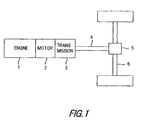
- Fig. 1 is a system diagram of a hybrid vehicle showing one embodiment of this invention.
- motor-generator 2 An electric motor which also functions as a generator (referred to hereafter as motor-generator) 2 is connected to the output side of an internal combustion engine (referred to hereafter as engine) 1, and a transmission 3 is connected to this motor-generator 2.
- engine an internal combustion engine
- a vehicle shaft 6 on the driving wheel side is driven by a drive shaft 4 on the output side of the transmission 3 via a differential gear 5.
- the motor-generator 2 is used to perform cranking of the engine 1 when the engine is started. If the vehicle is provided with an idle stop function which can stop the engine 1 automatically, such as when the vehicle is brought to a temporary halt, the motor-generator 2 starts the engine 1 automatically each time the conditions are satisfied for releasing idle stop once the idle stop function has been invoked.
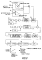
- Fig. 2 is a system diagram of the power supply system in this hybrid vehicle.
- a high voltage battery 11 is a power supply which can be charged and discharged having a rated voltage of approximately 42V, and which functions as the power supply for the motor-generator 2.
- a lead-acid battery a lead storage battery having an electrode of a lead grid comprising lead oxide whereof the composition changes during charging and discharging and an electrolyte of dilute sulfuric acid.
- triphase alternating current generated by the motor-generator 2 is converted to direct current by an inverter 12, and is supplied to the high voltage battery 11 via a junction box 13.
- a low voltage battery 14 is a lead-acid battery of rated voltage approximately 14V which is generally used as a power supply for vehicle-mounted electrical loads including an engine auxiliary load, and it stores part of the power generated by the motor-generator 2 via a DC/DC converter 15 after passing through the inverter 12 and junction box 13.
- 16 is a control unit which controls the operation of the motor-generator 2.
- the control unit 16 receives input of various running conditions including an engine rotation speed Ne from a rotation speed sensor 17, a speed ratio of the transmission from a speed ratio sensor 18 and ON/OFF of an air-conditioner from a air-conditioner sensor 19, as well as detection values such as an SOC (State of Charge) which is the actual charging amount of the high voltage battery 11, a generation current I-MG generated by the motor-generator 2 and converted by the inverter 12, and a charging current I-42 to the high voltage battery 11, and controls the motor-generator 2 based thereon.
- SOC State of Charge
- Fig. 3 is a control block diagram showing the charging current control of the motor-generator 2 by the control unit 16.
- This control unit comprises a microprocessor.
- a target charging amount setting unit 21 sets a target charging amount TSOC of the high voltage battery 11.
- the target charging amount TSOC is set to, for example, 90% of the charging amount when the battery is fully charged.
- a charging amount detecting unit 22 detects the actual charging amount SOC of the high voltage battery 11. Specifically, the current during charging and discharging of the high voltage battery 11 detected by a current sensor is integrated over time, the internal resistance is computed from sample values of current and voltage duiing discharging, and calculated based on internal resistance estimation values corrected according to various environmental factors.
- the charging amount SOC may be calculated as a percentage (%) relative to the fully charged state, or calculated as an absolute amount (A.Hr).
- a target charging current computing unit 23 compares the target charging amount TSOC with the actual charging amount SOC, multiplies by a gain based on proportional integral control, computes a feedback control amount of the charging amount, converts this to a current, and thereby computes a target charging current to the high voltage battery 11.
- a charging current table based on the SOC can also be provided.
- the voltage of the high voltage battery 11 may also be feedback controlled to a target voltage.
- the target voltage of the high voltage battery 11 e.g., 44V
- the actual voltage is detected
- a voltage feedback control amount is computed based on a comparison of the target voltage with the actual voltage, this is converted to a current
- the target charging current to the high voltage battery 11 is then computed.
- the target charging current computed from battery demand may also be corrected according to the motor efficiency, engine state or vehicle demand. In this case, the correction gain is large when the motor efficiency is good, and the correction grain is large even when the engine fuel consumption is low.
- the correction gain is also large when, for example, the vehicle is required to climb a hill due to navigational information.
- a first limiter 24 compares the target charging current computed by the target charging current computing unit 23 with a limiter value, and when the target charging current is equal to or greater than the limiter value, the target charging current is limited to the limiter value.
- This limiter value is specifically computed by multiplying a limiter basic value computed from the SOC and battery temperature by a limiter value basic value computing unit 34, by a limiter correction gain computed from the battery deterioration degree by a limiter correction gain computing unit 35.
- the limitation of the target charging current by the first limiter is specifically performed as shown by the flowchart of Fig. 4.
- a limiter value LT1 is read, and in a step S12, it is determined whether or not the target charging current ⁇ LT1.
- the target charging current ⁇ LT1 is changed to LT1 in a step S13.
- the limiter value LT1 is a permitted value showing by how much the high voltage battery can be charged to prevent overcharging of the high voltage battery.
- a charging current detecting unit 25 detects the actual charging current I-MG of the motor-generator 2 by a current sensor.
- a charging current detecting unit 26 also detects the actual charging current I-42 to the high voltage battery 11 by a current sensor.
- the motor torque command is set to 0, and charging is not performed until the SOC decreases to a predetermined value due to electrical load consumption.
- a second limiter 31 compares the target generation current determined by the target generation current determining unit 30 with a preset limiter value depending on running conditions, and when the target generation current is equal to or greater than the limiter value, the target generation current is limited to the limiter value.
- the limitation of the target generation current by the second limiter is specifically performed as shown by the flowchart of Fig. 5.
- a limiter value LT2 is computed based for example on the engine rotation speed Ne, and in a step S22, it is determined whether are not the target generation current ⁇ LT2.
- the routine proceeds to a step S23, and the target generation current is set equal to LT2.
- the limiter value LT2 is set according to the engine rotation speed Ne so that it is smaller at low rotation speeds and larger at high rotation speeds as shown in Fig. 6.
- the following variation may also be used.
- the limiter value LT2 is set according to the engine rotation speed Ne so that it is small at low rotation speeds and large at high rotation speeds, as shown in Fig. 7. This is corrected according to the ON/OFF state of the air-conditioner which represents vehicle-mounted electrical loads so that it is relatively large when the air-conditioner is OFF and relatively small when the air-conditioner is ON, i.e., two limiter values are taken.
- the correction may be applied according to the ON/OFF state of vehicle-mounted electrical loads other than the air-conditioner (e.g., the power steering or lights, etc.).
- the aforesaid limiter value LT2 is set according to the engine rotation speed Ne to small at low rotation speeds and large at high rotation speeds, this value being further corrected according to the speed ratio of the transmission.
- the limiter value is set to be relatively large when the speed ratio is small (high gear), and set to be relatively small when the speed ratio is large (low gear). This is to increase the energy recovery amount at low speed ratios (high gear).
- the deceleration is small when the speed ratio is small, and hence the deceleration is prevented from becoming excessive even if the deceleration energy recovery amount is increased.
- Fig. 9 shows the relation of the limiter value LT2 according to the ON/OFF state of the air-conditioner regardless of the engine rotation speed, the value being set large when the air conditioner is OFF and set small when the air-conditioner is ON.
- the limiter value may also be set according to the ON/OFF state of vehicle-mounted electrical loads other than the air-conditioner (e.g., the power steering or lights), as described above.
- the limiter value LT2 may also be set depending only on the speed ratio regardless of the engine rotation speed, i.e., it may be set to be larger at low rotation speeds (high gear) and smaller at high rotation speeds (low gear).
- a target torque computing unit 32 converts the target generation current determined by the aforesaid target generation current determining unit 30 and limited as necessary by the second limiter 31, to a target torque of the motor-generator 2 by looking up a table in Fig. 3 (a).
- a motor-generator control unit (current command unit) 33 determines a current command value supplied to the motor-generator 2 necessary to obtain the target torque by looking up a map in Fig. 3 (b) based on this target torque and the engine rotation speed Ne, and thereby controls the generation current of the motor-generator 2.
Landscapes
- Engineering & Computer Science (AREA)
- Chemical & Material Sciences (AREA)
- Combustion & Propulsion (AREA)
- Transportation (AREA)
- Mechanical Engineering (AREA)
- Power Engineering (AREA)
- Electric Propulsion And Braking For Vehicles (AREA)
- Hybrid Electric Vehicles (AREA)
- Arrangement Or Mounting Of Propulsion Units For Vehicles (AREA)
- Control Of Vehicle Engines Or Engines For Specific Uses (AREA)
- Control Of Charge By Means Of Generators (AREA)
Abstract
Description
- This invention relates to a control device of a hybrid vehicle which comprises an internal combustion engine as a source of power for running a vehicle and an electric motor having a high voltage battery as a power supply, the electric motor being used as a generator when the vehicle is decelerating, and charged by the high voltage battery and a low voltage battery for vehicle-mounted electrical loads.
- Recently, a hybrid vehicle has been developed comprising an internal combustion engine (gasoline engine) as a source of motive power for running a vehicle, and an electric motor having a high voltage battery as a power supply, as disclosed in Japanese patent publication Tokkai Hei 10-304511.
- In this hybrid vehicle, the electric motor is used as a generator when the vehicle is decelerating (coasting) as a way of recovering the vehicle's inertia energy while it is decelerating, and the power so generated is used to charge the high voltage battery and low voltage battery for supplying vehicle-mounted electrical loads.
- Control of the current when power is being generated by the electrical motor is based on the charge state of the high voltage battery, and the current supplied to electrical loads (vehicle-mounted electrical loads) such as auxiliary devices mounted on the vehicle. Specifically, a target charge current supplied to the high voltage battery according to the charge state of the high voltage battery is computed, an electrical load current supplied to the vehicle-mounted electrical loads is detected, and the electric motor is controlled so that the sum of these values coincides with the current generated by the electrical motor.
- During deceleration, if the generated current is too large when energy recovery is being performed, the high voltage battery will be overcharged. This leads to early deterioration of the battery and excessive vehicle deceleration due to increase of the load on the electric motor, and consequently, the driver will experience an uncomfortable deceleration feeding.
- If the high voltage battery is a lead-acid battery, which is used for its low cost in comparison to expensive lithium ion batteries or nickel-hydrogen batteries, it easily degenerates due to overcharging, and it is especially necessary to prevent overcharging.
- It is therefore an object of this invention to prevent overcharging of the battery, prevent deterioration of the battery due to overcharging, and to prevent the deceleration from becoming too large during energy recovery when the vehicle is decelerating.
- It is a further object of this invention to increase the energy recovery efficiency when the vehicle is decelerating. In order to achieve the above objects the invention provides a control device of a hybrid vehicle which provides an internal combustion engine as a power source for running a vehicle together with an electric motor. The control device comprises a high voltage battery which functions as a power source for the electric motor, a low voltage battery for vehicle-mounted electrical loads, a sensor for detecting a vehicle running state, and a microprocessor which controls the electric motor is programmed to determine a deceleration state of the vehicle, to cause the electric motor to function as a generator in the deceleration state, to perform control to charge the high voltage battery and low voltage battery by the current generated by the electric motor, and to limit the current generated by the electric motor by a limiter, and vary the value of this limiter according to the running state.
- The details as well as other features and advantages of the invention are set forth in the remainder of the specification and are shown in the accompanying drawings.
-
- Fig. 1 is a system diagram of a hybrid vehicle showing one embodiment of this invention.
- Fig. 2 is a system diagram of a power supply system in the hybrid vehicle.
- Fig. 3 is a control block diagram of generation current control of a motor-generator.
- Fig. 4 is a flowchart of a control operation performed by a first limiter.
- Fig. 5 is a flowchart showing a control operation performed by a second limiter.
- Fig. 6 is a diagram showing a typical setting (1) of a limiter value of the second limiter.
- Fig. 7 is a diagram showing a typical setting (2) of a limiter value of the second limiter.
- Fig. 8 is a diagram showing a typical setting (3) of a limiter value of the second limiter.
- Fig. 9 is a diagram showing a typical setting (4) of a limiter value of the second limiter.
- Fig. 10 is a diagram showing a typical setting (5) of a limiter value of the second limiter.
-
- Fig. 1 is a system diagram of a hybrid vehicle showing one embodiment of this invention.
- An electric motor which also functions as a generator (referred to hereafter as motor-generator) 2 is connected to the output side of an internal combustion engine (referred to hereafter as engine) 1, and a
transmission 3 is connected to this motor-generator 2. A vehicle shaft 6 on the driving wheel side is driven by adrive shaft 4 on the output side of thetransmission 3 via adifferential gear 5. - The motor-
generator 2 is used to perform cranking of theengine 1 when the engine is started. If the vehicle is provided with an idle stop function which can stop theengine 1 automatically, such as when the vehicle is brought to a temporary halt, the motor-generator 2 starts theengine 1 automatically each time the conditions are satisfied for releasing idle stop once the idle stop function has been invoked. - When the torque of the motor-
generator 2 is added to the torque of theengine 1 such as when the vehicle is accelerating the vehicle runs on high power. On the other hand, when the vehicle is decelerating the motor-generator 2 generates electric power as a generator to recover the energy of inertia of the vehicle while it is running charges the battery, and supplies current to other electrical loads. - Fig. 2 is a system diagram of the power supply system in this hybrid vehicle.
- A
high voltage battery 11 is a power supply which can be charged and discharged having a rated voltage of approximately 42V, and which functions as the power supply for the motor-generator 2. Specifically, it is a lead-acid battery (a lead storage battery having an electrode of a lead grid comprising lead oxide whereof the composition changes during charging and discharging and an electrolyte of dilute sulfuric acid). - When the motor-
generator 2 is functioning as a generator to generate electricity, triphase alternating current generated by the motor-generator 2 is converted to direct current by aninverter 12, and is supplied to thehigh voltage battery 11 via ajunction box 13. - Conversely, when the motor-
generator 2 is functioning as a motor and discharging, power from thehigh voltage battery 11 is converted to triphase alternating current via thejunction box 13 and inverter 12, and supplied to the motor-generator 2. - A
low voltage battery 14 is a lead-acid battery of rated voltage approximately 14V which is generally used as a power supply for vehicle-mounted electrical loads including an engine auxiliary load, and it stores part of the power generated by the motor-generator 2 via a DC/DC converter 15 after passing through theinverter 12 andjunction box 13. - 16 is a control unit which controls the operation of the motor-
generator 2. - The
control unit 16 receives input of various running conditions including an engine rotation speed Ne from arotation speed sensor 17, a speed ratio of the transmission from a speed ratio sensor 18 and ON/OFF of an air-conditioner from a air-conditioner sensor 19, as well as detection values such as an SOC (State of Charge) which is the actual charging amount of thehigh voltage battery 11, a generation current I-MG generated by the motor-generator 2 and converted by theinverter 12, and a charging current I-42 to thehigh voltage battery 11, and controls the motor-generator 2 based thereon. - Fig. 3 is a control block diagram showing the charging current control of the motor-
generator 2 by thecontrol unit 16. This control unit comprises a microprocessor. - A target charging
amount setting unit 21 sets a target charging amount TSOC of thehigh voltage battery 11. Herein, the target charging amount TSOC is set to, for example, 90% of the charging amount when the battery is fully charged. - A charging
amount detecting unit 22 detects the actual charging amount SOC of thehigh voltage battery 11. Specifically, the current during charging and discharging of thehigh voltage battery 11 detected by a current sensor is integrated over time, the internal resistance is computed from sample values of current and voltage duiing discharging, and calculated based on internal resistance estimation values corrected according to various environmental factors. The charging amount SOC may be calculated as a percentage (%) relative to the fully charged state, or calculated as an absolute amount (A.Hr). - A target charging
current computing unit 23 compares the target charging amount TSOC with the actual charging amount SOC, multiplies by a gain based on proportional integral control, computes a feedback control amount of the charging amount, converts this to a current, and thereby computes a target charging current to thehigh voltage battery 11. A charging current table based on the SOC can also be provided. - The voltage of the
high voltage battery 11 may also be feedback controlled to a target voltage. Specifically, the target voltage of the high voltage battery 11 (e.g., 44V) is set, the actual voltage is detected, a voltage feedback control amount is computed based on a comparison of the target voltage with the actual voltage, this is converted to a current, and the target charging current to thehigh voltage battery 11 is then computed. The target charging current computed from battery demand may also be corrected according to the motor efficiency, engine state or vehicle demand. In this case, the correction gain is large when the motor efficiency is good, and the correction grain is large even when the engine fuel consumption is low. The correction gain is also large when, for example, the vehicle is required to climb a hill due to navigational information. - A
first limiter 24 compares the target charging current computed by the target chargingcurrent computing unit 23 with a limiter value, and when the target charging current is equal to or greater than the limiter value, the target charging current is limited to the limiter value. This limiter value is specifically computed by multiplying a limiter basic value computed from the SOC and battery temperature by a limiter value basicvalue computing unit 34, by a limiter correction gain computed from the battery deterioration degree by a limiter correctiongain computing unit 35. - The limitation of the target charging current by the first limiter is specifically performed as shown by the flowchart of Fig. 4.
- In a step S11, a limiter value LT1 is read, and in a step S12, it is determined whether or not the target charging current ≧ LT1. When the target charging current ≧ LT1, the target charging current is changed to LT1 in a step S13. Here, the limiter value LT1 is a permitted value showing by how much the high voltage battery can be charged to prevent overcharging of the high voltage battery.
- In Fig 3, a charging
current detecting unit 25 detects the actual charging current I-MG of the motor-generator 2 by a current sensor. A chargingcurrent detecting unit 26 also detects the actual charging current I-42 to thehigh voltage battery 11 by a current sensor. - An electrical load current detecting unit (estimating unit) 27 subtracts the charging current I-42 to the
high voltage battery 11 from the generation current I-MG of the motor-generator 2, and thereby computes an electrical load currenthigh voltage battery 11 is subtracted from the generation current of the motor-generator 2, the charging current to thelow voltage battery 14 is calculated, and the charging current to thislow voltage battery 14 is taken as the electrical load current. - A target generation
current computing unit 28 for computing the target generation current when the battery is charging, is computed by the aforesaid target chargingcurrent computing unit 23, the electrical load current calculated by the aforesaid electrical load current detecting unit (estimating unit) 27 is added to the target charging current which has passed through thefirst limiter 24, and the target generation current of the motor-generator 2 (= target charging current + electrical load current) is computed. - When the SOC has reached the target SOC, the motor torque command is set to 0, and charging is not performed until the SOC decreases to a predetermined value due to electrical load consumption.
- A
second limiter 31 compares the target generation current determined by the target generation current determiningunit 30 with a preset limiter value depending on running conditions, and when the target generation current is equal to or greater than the limiter value, the target generation current is limited to the limiter value. - The limitation of the target generation current by the second limiter is specifically performed as shown by the flowchart of Fig. 5.
- In a step S21, a limiter value LT2 is computed based for example on the engine rotation speed Ne, and in a step S22, it is determined whether are not the target generation current ≧ LT2. When the target generation current ≧ LT2, the routine proceeds to a step S23, and the target generation current is set equal to LT2.
- Here, the limiter value LT2 is set according to the engine rotation speed Ne so that it is smaller at low rotation speeds and larger at high rotation speeds as shown in Fig. 6.
- When the vehicle deceleration characteristics are constant, as the inertia energy which can be absorbed during deceleration is high at high engine rotation speeds and low at low engine rotation speeds, a torque equivalent amount which can be absorbed by the motor-
generator 2 at the present engine rotation speed Ne is taken as the limiter value of the motor generation current. - Regarding the limiter value LT2 of the second limiter, the following variation may also be used.
- In this variation, the limiter value LT2 is set according to the engine rotation speed Ne so that it is small at low rotation speeds and large at high rotation speeds, as shown in Fig. 7. This is corrected according to the ON/OFF state of the air-conditioner which represents vehicle-mounted electrical loads so that it is relatively large when the air-conditioner is OFF and relatively small when the air-conditioner is ON, i.e., two limiter values are taken.
- This is because the deceleration is smaller when the air-conditioner is OFF than when it is ON, and is intended to increase the energy recovery amount when the air-conditioner is OFF for the same deceleration.
- Instead of correcting according to the ON/OFF state of the air-conditioner, the correction may be applied according to the ON/OFF state of vehicle-mounted electrical loads other than the air-conditioner (e.g., the power steering or lights, etc.).
- In Fig. 8, the aforesaid limiter value LT2 is set according to the engine rotation speed Ne to small at low rotation speeds and large at high rotation speeds, this value being further corrected according to the speed ratio of the transmission. The limiter value is set to be relatively large when the speed ratio is small (high gear), and set to be relatively small when the speed ratio is large (low gear). This is to increase the energy recovery amount at low speed ratios (high gear). The deceleration is small when the speed ratio is small, and hence the deceleration is prevented from becoming excessive even if the deceleration energy recovery amount is increased.
- On the other hand, Fig. 9 shows the relation of the limiter value LT2 according to the ON/OFF state of the air-conditioner regardless of the engine rotation speed, the value being set large when the air conditioner is OFF and set small when the air-conditioner is ON. The limiter value may also be set according to the ON/OFF state of vehicle-mounted electrical loads other than the air-conditioner (e.g., the power steering or lights), as described above.
- Further, as shown in Fig 10, the limiter value LT2 may also be set depending only on the speed ratio regardless of the engine rotation speed, i.e., it may be set to be larger at low rotation speeds (high gear) and smaller at high rotation speeds (low gear).
- In Fig. 3, a target
torque computing unit 32 converts the target generation current determined by the aforesaid target generation current determiningunit 30 and limited as necessary by thesecond limiter 31, to a target torque of the motor-generator 2 by looking up a table in Fig. 3 (a). - A motor-generator control unit (current command unit) 33 determines a current command value supplied to the motor-
generator 2 necessary to obtain the target torque by looking up a map in Fig. 3 (b) based on this target torque and the engine rotation speed Ne, and thereby controls the generation current of the motor-generator 2. - Due to the above control, using a lead-acid battery as the
high voltage battery 11, deterioration of the battery due to overcharging is prevented by charging only to a permitted amount, the deceleration is prevented from becoming too large, and energy recovery during deceleration can be performed efficiently. - The entire contents of Japanese Patent Application P11-248389 (filed September 2, 1999) is incorporated herein by reference. Although the invention has been described above by reference to certain embodiments of the invention, the invention is not limited to the embodiments described above. Modifications and variations of the embodiments described above will occur to those skilled in the art, in light of the above teaching. The scope of the invention is defined with reference to the following claims.
Claims (9)
- A control device of a hybrid vehicle which comprises an internal combustion engine (1) as a power source for running a vehicle together with an electric motor (2), the vehicle comprising:a high voltage battery (11) which functions as a power source for the electric motor (2),a low voltage battery (14) for vehicle-mounted electrical loads,a sensor (17,18,19) for detecting a vehicle running state, anda microprocessor (16) which controls the electric motor (2) is programmed to:determine a deceleration state of the vehicle,cause the electric motor (2) to function as a generator in the deceleration state,perform control to charge the high voltage battery (11) and low voltage battery (14) by the current generated by the electric motor (2), andlimit the current generated by the electric motor (2) by a limiter (31), and vary the value of this limiter (31) according to the running state.
- A control device as defined in Claim 1, wherein the microprocessor (16) is programmed to vary the limiter value according to the ON/OFF state of the vehicle-mounted electrical loads.
- A control device as defined in Claim 1, wherein the microprocessor (16) is programmed to vary the limiter value according to a speed ratio of a transmission.
- A control device as defined in Claim 1, wherein the microprocessor (16) is programmed to vary the limiter value according to an engine rotation speed.
- A control device as defined in Claim 4, wherein the microprocessor (16) is programmed to further vary the limiter value according to the ON/OFF state of the vehicle-mounted electrical loads.
- A control device as defined in Claim 4, wherein the microprocessor (16) is programmed to further vary the limiter value according to a speed ratio of a transmission.
- A control device as defined in Claim 1, wherein the microprocessor (16) is further programmed to:compute a target charging current to the high voltage battery (11) according to the charge state of the high voltage battery (11),compute an electrical load current supplied to the vehicle-mounted electrical loads,compute a target generation current generated by the electric motor (2) by adding the target charging current and electrical load current,limit the target generation current by the limiter (31), andlimit the target generation current by another limiter (24).
- A control device as defined in Claim 7, wherein the microprocessor(16) is further programmed to set the limiter value due to the other limiter according to the battery state of charge, battery temperature and battery deterioration degree.
- A control device as defined in Claim 1, wherein a lead-acid battery is used as the high voltage battery (11).
Applications Claiming Priority (2)
| Application Number | Priority Date | Filing Date | Title |
|---|---|---|---|
| JP24838999A JP3967043B2 (en) | 1999-09-02 | 1999-09-02 | Control device for hybrid vehicle |
| JP24838999 | 1999-09-02 |
Publications (3)
| Publication Number | Publication Date |
|---|---|
| EP1080983A2 true EP1080983A2 (en) | 2001-03-07 |
| EP1080983A3 EP1080983A3 (en) | 2001-03-14 |
| EP1080983B1 EP1080983B1 (en) | 2011-12-28 |
Family
ID=17177389
Family Applications (1)
| Application Number | Title | Priority Date | Filing Date |
|---|---|---|---|
| EP00118610A Expired - Lifetime EP1080983B1 (en) | 1999-09-02 | 2000-08-28 | Control device of a hybrid vehicle |
Country Status (3)
| Country | Link |
|---|---|
| US (1) | US6452286B1 (en) |
| EP (1) | EP1080983B1 (en) |
| JP (1) | JP3967043B2 (en) |
Cited By (6)
| Publication number | Priority date | Publication date | Assignee | Title |
|---|---|---|---|---|
| FR2828446A1 (en) * | 2001-08-07 | 2003-02-14 | Toyota Motor Co Ltd | CONTROL DEVICE AND METHOD FOR VEHICLE EQUIPPED WITH INTERNAL COMBUSTION ENGINE |
| FR2851856A1 (en) * | 2003-02-27 | 2004-09-03 | Peugeot Citroen Automobiles Sa | Control of electrical machine in series hybrid vehicle, uses control of power demand to charge battery using an adaptive law with gain adjusted as a function of vehicle operating conditions |
| WO2008133784A1 (en) * | 2007-04-30 | 2008-11-06 | Caterpillar Inc. | System for controlling a hybrid energy system |
| FR2934528A1 (en) * | 2008-08-01 | 2010-02-05 | Michelin Soc Tech | Traction and braking torque controlling system for four-wheeled vehicle, has generator for generating resulting torque set point to control torque exerted on one of rear wheels by electrical machine at each instant |
| CN102891524A (en) * | 2011-07-21 | 2013-01-23 | 现代自动车株式会社 | Battery charging system for vehicle and control method of the same |
| CN103448728A (en) * | 2013-06-24 | 2013-12-18 | 浙江吉利汽车研究院有限公司杭州分公司 | Control method and system of traditional vehicle air conditioner in hybrid electric vehicle |
Families Citing this family (43)
| Publication number | Priority date | Publication date | Assignee | Title |
|---|---|---|---|---|
| JP3969623B2 (en) * | 2000-06-30 | 2007-09-05 | 本田技研工業株式会社 | Engine drive power generator |
| JP3904388B2 (en) * | 2000-12-04 | 2007-04-11 | 松下電器産業株式会社 | Control device for hybrid vehicle |
| US6690140B2 (en) * | 2001-08-30 | 2004-02-10 | International Truck Intellectual Property Company, Llc | Vehicle electrical system |
| JP3638263B2 (en) * | 2001-09-10 | 2005-04-13 | 本田技研工業株式会社 | Vehicle drive device |
| EP1747932B1 (en) * | 2002-08-27 | 2011-09-28 | JTEKT Corporation | Electrical load controlling device |
| JP4111156B2 (en) * | 2004-03-12 | 2008-07-02 | アイシン・エィ・ダブリュ株式会社 | Drive control device, drive control method, and program |
| US7100362B2 (en) * | 2004-07-30 | 2006-09-05 | Ford Global Technologies, Llc | Vehicle and method for operating a vehicle to reduce exhaust emissions |
| US7267191B2 (en) * | 2004-07-30 | 2007-09-11 | Ford Global Technologies, Llc | System and method for battery protection strategy for hybrid electric vehicles |
| JP3918835B2 (en) * | 2004-08-03 | 2007-05-23 | 日産自動車株式会社 | Vehicle battery power compensation control device |
| JP2006094689A (en) * | 2004-08-25 | 2006-04-06 | Toyota Motor Corp | Electric vehicle and control method thereof |
| JP4491839B2 (en) * | 2005-09-07 | 2010-06-30 | 株式会社デンソー | Generator control device |
| US7539562B2 (en) | 2006-03-06 | 2009-05-26 | Gm Global Technology Operations, Inc. | Hybrid vehicle powertrain control method and apparatus |
| JP4899576B2 (en) * | 2006-03-28 | 2012-03-21 | アイシン精機株式会社 | Control device for vehicle drive system |
| JP4462224B2 (en) * | 2006-03-31 | 2010-05-12 | マツダ株式会社 | Vehicle hybrid system |
| JP4379484B2 (en) * | 2007-04-06 | 2009-12-09 | 株式会社デンソー | Vehicle system |
| KR100957274B1 (en) * | 2008-04-21 | 2010-05-12 | 현대자동차주식회사 | Secondary load compensation method of hybrid vehicle |
| KR100986500B1 (en) | 2008-10-28 | 2010-10-08 | 현대자동차주식회사 | Multi-Stack Fuel Cell Hybrid System |
| BR112012005366A2 (en) | 2009-09-15 | 2020-09-15 | Kpit Cummins Infosystems Ltd. | engine assistance method for a hybrid vehicle based on user input, its system and device |
| WO2011039771A2 (en) | 2009-09-15 | 2011-04-07 | Kpit Cummins Infosystems Ltd. | Motor assistance for a hybrid vehicle based on predicted driving range |
| CN102483020B (en) | 2009-09-15 | 2015-03-04 | Kpit技术有限责任公司 | Method of converting vehicle into hybrid vehicle |
| US8423214B2 (en) | 2009-09-15 | 2013-04-16 | Kpit Cummins Infosystems, Ltd. | Motor assistance for a hybrid vehicle |
| JP5387389B2 (en) * | 2009-12-25 | 2014-01-15 | アイシン・エィ・ダブリュ株式会社 | Target charging power setting device, method and program |
| US8364332B2 (en) * | 2010-01-15 | 2013-01-29 | GM Global Technology Operations LLC | Control algorithm for low-voltage circuit in hybrid and conventional vehicles |
| WO2012032605A1 (en) * | 2010-09-07 | 2012-03-15 | トヨタ自動車株式会社 | Control apparatus for vehicle driving apparatus |
| US8549838B2 (en) | 2010-10-19 | 2013-10-08 | Cummins Inc. | System, method, and apparatus for enhancing aftertreatment regeneration in a hybrid power system |
| CN102009650B (en) * | 2010-11-25 | 2013-01-02 | 奇瑞汽车股份有限公司 | Method for controlling generating voltage of electromobile mileage supercharger |
| US8742701B2 (en) | 2010-12-20 | 2014-06-03 | Cummins Inc. | System, method, and apparatus for integrated hybrid power system thermal management |
| US8833496B2 (en) | 2010-12-20 | 2014-09-16 | Cummins Inc. | System, method, and apparatus for battery pack thermal management |
| US8473177B2 (en) | 2010-12-31 | 2013-06-25 | Cummins, Inc. | Apparatuses, methods, and systems for thermal management of hybrid vehicle SCR aftertreatment |
| US9096207B2 (en) | 2010-12-31 | 2015-08-04 | Cummins Inc. | Hybrid vehicle powertrain cooling system |
| US9043060B2 (en) | 2010-12-31 | 2015-05-26 | Cummins Inc. | Methods, systems, and apparatuses for driveline load management |
| CN117048579A (en) | 2011-01-13 | 2023-11-14 | 卡明斯公司 | Systems, methods, and apparatus for controlling power output distribution in a hybrid powertrain |
| US20120323414A1 (en) * | 2011-06-15 | 2012-12-20 | Wei-Hua Lu | Hybrid electric vehicle |
| JP2013255365A (en) * | 2012-06-07 | 2013-12-19 | Suzuki Motor Corp | Vehicle control device |
| JP6191575B2 (en) | 2014-08-06 | 2017-09-06 | トヨタ自動車株式会社 | Power supply |
| DE102014218134A1 (en) * | 2014-09-10 | 2016-03-10 | Bayerische Motoren Werke Aktiengesellschaft | Energy supply of a vehicle electrical system of a hybrid motor vehicle |
| US9821663B2 (en) * | 2014-10-20 | 2017-11-21 | Cummins Inc. | Systems and methods for battery regeneration based on engine loading |
| US9975619B1 (en) * | 2017-01-11 | 2018-05-22 | Brunswick Corporation | PCM controlled charging system |
| KR102417897B1 (en) | 2017-09-07 | 2022-07-07 | 현대자동차주식회사 | Apparatus for controlling charging in environment-friendly vehicle, system having the same and method thereof |
| WO2020021944A1 (en) * | 2018-07-25 | 2020-01-30 | 株式会社Gsユアサ | Estimation device, battery, vehicle, and estimation method |
| US10889191B1 (en) * | 2019-10-03 | 2021-01-12 | Ford Global Technologies, Llc | Methods and system for limiting torque in a BEV |
| JP7753133B2 (en) * | 2022-03-02 | 2025-10-14 | 株式会社豊田自動織機 | Hybrid vehicles |
| CN114825530B (en) * | 2022-04-28 | 2026-04-10 | 东风柳州汽车有限公司 | Methods, equipment, storage media and devices for charging automotive batteries |
Citations (1)
| Publication number | Priority date | Publication date | Assignee | Title |
|---|---|---|---|---|
| GB2319407A (en) | 1996-06-14 | 1998-05-20 | Hino Motors Ltd | Controller for on-vehicle battery |
Family Cites Families (18)
| Publication number | Priority date | Publication date | Assignee | Title |
|---|---|---|---|---|
| US5602459A (en) * | 1988-07-13 | 1997-02-11 | Electronic Development Inc. | Fuel saving multi-battery charging system and method |
| JP3163622B2 (en) * | 1990-07-05 | 2001-05-08 | 日産自動車株式会社 | Electric car |
| US5156932A (en) * | 1991-05-02 | 1992-10-20 | Globe-Union, Inc. | Simple optimized lead-acid battery |
| JPH04347536A (en) * | 1991-05-22 | 1992-12-02 | Honda Motor Co Ltd | Electric load limiter for vehicle |
| US5670861A (en) * | 1995-01-17 | 1997-09-23 | Norvik Tractions Inc. | Battery energy monitoring circuits |
| JP3534271B2 (en) * | 1995-04-20 | 2004-06-07 | 株式会社エクォス・リサーチ | Hybrid vehicle |
| US5637987A (en) * | 1995-12-18 | 1997-06-10 | General Motors Corporation | Regenerative vehicle launch |
| JP3617183B2 (en) * | 1996-05-08 | 2005-02-02 | トヨタ自動車株式会社 | Electric vehicle power supply |
| US5783872A (en) * | 1996-07-25 | 1998-07-21 | Northrop Grumman Corporation | Auxiliary battery voltage/temperature compensation for automotive 12 volt system for electric vehicles |
| US5925938A (en) * | 1997-03-05 | 1999-07-20 | Ford Global Technologies, Inc. | Electrical system for a motor vehicle |
| JP3687270B2 (en) * | 1997-04-23 | 2005-08-24 | 日産自動車株式会社 | Generator control method for hybrid electric vehicle |
| JPH11136801A (en) * | 1997-10-24 | 1999-05-21 | Denso Corp | Drive device for multiple battery type electric vehicle |
| JPH11136808A (en) * | 1997-10-31 | 1999-05-21 | Nissan Motor Co Ltd | Power generation control device for hybrid vehicle |
| US6020697A (en) * | 1997-11-14 | 2000-02-01 | Honda Giken Kogyo Kabushiki Kaisha | Hybrid vehicle |
| JP3711720B2 (en) * | 1997-11-28 | 2005-11-02 | 株式会社デンソー | Hybrid electric vehicle |
| US5986416A (en) * | 1997-12-09 | 1999-11-16 | Dubois; Jean-Marie | Apparatus and method for driving a mechanically-driven device in an electrical vehicle |
| JP3478723B2 (en) * | 1998-02-03 | 2003-12-15 | 本田技研工業株式会社 | Control device for hybrid vehicle |
| JP3685945B2 (en) * | 1999-03-09 | 2005-08-24 | 本田技研工業株式会社 | Engine control device for hybrid vehicle |
-
1999
- 1999-09-02 JP JP24838999A patent/JP3967043B2/en not_active Expired - Fee Related
-
2000
- 2000-08-28 EP EP00118610A patent/EP1080983B1/en not_active Expired - Lifetime
- 2000-08-30 US US09/652,261 patent/US6452286B1/en not_active Expired - Lifetime
Patent Citations (1)
| Publication number | Priority date | Publication date | Assignee | Title |
|---|---|---|---|---|
| GB2319407A (en) | 1996-06-14 | 1998-05-20 | Hino Motors Ltd | Controller for on-vehicle battery |
Cited By (11)
| Publication number | Priority date | Publication date | Assignee | Title |
|---|---|---|---|---|
| FR2828446A1 (en) * | 2001-08-07 | 2003-02-14 | Toyota Motor Co Ltd | CONTROL DEVICE AND METHOD FOR VEHICLE EQUIPPED WITH INTERNAL COMBUSTION ENGINE |
| FR2851856A1 (en) * | 2003-02-27 | 2004-09-03 | Peugeot Citroen Automobiles Sa | Control of electrical machine in series hybrid vehicle, uses control of power demand to charge battery using an adaptive law with gain adjusted as a function of vehicle operating conditions |
| EP1454786A3 (en) * | 2003-02-27 | 2006-11-15 | Peugeot Citroen Automobiles SA | Control of an electrical machine in a serial hybrid vehicle |
| WO2008133784A1 (en) * | 2007-04-30 | 2008-11-06 | Caterpillar Inc. | System for controlling a hybrid energy system |
| US8062169B2 (en) | 2007-04-30 | 2011-11-22 | Caterpillar Inc. | System for controlling a hybrid energy system |
| CN101668653B (en) * | 2007-04-30 | 2012-10-10 | 卡特彼勒公司 | System for controlling a hybrid energy system |
| FR2934528A1 (en) * | 2008-08-01 | 2010-02-05 | Michelin Soc Tech | Traction and braking torque controlling system for four-wheeled vehicle, has generator for generating resulting torque set point to control torque exerted on one of rear wheels by electrical machine at each instant |
| CN102891524A (en) * | 2011-07-21 | 2013-01-23 | 现代自动车株式会社 | Battery charging system for vehicle and control method of the same |
| CN102891524B (en) * | 2011-07-21 | 2016-06-08 | 现代自动车株式会社 | For battery charge system and the control method thereof of vehicle |
| CN103448728A (en) * | 2013-06-24 | 2013-12-18 | 浙江吉利汽车研究院有限公司杭州分公司 | Control method and system of traditional vehicle air conditioner in hybrid electric vehicle |
| CN103448728B (en) * | 2013-06-24 | 2016-03-02 | 浙江吉利汽车研究院有限公司杭州分公司 | Control method and system of traditional vehicle air conditioner in hybrid electric vehicle |
Also Published As
| Publication number | Publication date |
|---|---|
| JP2001078306A (en) | 2001-03-23 |
| US6452286B1 (en) | 2002-09-17 |
| EP1080983A3 (en) | 2001-03-14 |
| EP1080983B1 (en) | 2011-12-28 |
| JP3967043B2 (en) | 2007-08-29 |
Similar Documents
| Publication | Publication Date | Title |
|---|---|---|
| US6452286B1 (en) | Control device of a hybrid vehicle | |
| US6659213B2 (en) | Control device for hybrid vehicle | |
| US8660725B2 (en) | Control device of hybrid vehicle and hybrid vehicle | |
| US7267191B2 (en) | System and method for battery protection strategy for hybrid electric vehicles | |
| US11299140B2 (en) | Vehicle provided with generator | |
| US20100241376A1 (en) | Control apparatus and control method for secondary battery | |
| JP4026013B2 (en) | Torque control device | |
| US10160444B2 (en) | Vehicle | |
| US20190105979A1 (en) | Hybrid vehicle | |
| CN104220316A (en) | Electric power generation control system for hybrid automobile | |
| US11198368B2 (en) | Vehicular charging control system | |
| CN109314399B (en) | Vehicle Power System | |
| JPH11289607A (en) | Control device for hybrid vehicle | |
| JP3268107B2 (en) | Electric vehicle control device | |
| JP3700531B2 (en) | Control device for hybrid vehicle | |
| US20250001999A1 (en) | Techniques for managing power distribution between electrified vehicle loads and high voltage battery system during low state of charge conditions | |
| JP2973657B2 (en) | Power distribution system for series hybrid vehicles | |
| JP2001157306A (en) | Hybrid vehicle control device | |
| JP3092079B2 (en) | Hybrid electric vehicle | |
| JP2001211507A (en) | Hybrid vehicle control device | |
| JP3178139B2 (en) | Control device for electric vehicle | |
| JP3772875B2 (en) | Control device for hybrid vehicle | |
| JP3772876B2 (en) | Control device for hybrid vehicle | |
| JP2001157307A (en) | Hybrid vehicle control device | |
| US11970078B2 (en) | Vehicle accessory load control and power stability |
Legal Events
| Date | Code | Title | Description |
|---|---|---|---|
| PUAI | Public reference made under article 153(3) epc to a published international application that has entered the european phase |
Free format text: ORIGINAL CODE: 0009012 |
|
| PUAL | Search report despatched |
Free format text: ORIGINAL CODE: 0009013 |
|
| 17P | Request for examination filed |
Effective date: 20000828 |
|
| AK | Designated contracting states |
Kind code of ref document: A2 Designated state(s): DE FR GB |
|
| AX | Request for extension of the european patent |
Free format text: AL;LT;LV;MK;RO;SI |
|
| AK | Designated contracting states |
Kind code of ref document: A3 Designated state(s): AT BE CH CY DE DK ES FI FR GB GR IE IT LI LU MC NL PT SE |
|
| AX | Request for extension of the european patent |
Free format text: AL;LT;LV;MK;RO;SI |
|
| RIC1 | Information provided on ipc code assigned before grant |
Free format text: 7B 60L 11/12 A |
|
| AKX | Designation fees paid |
Free format text: DE FR GB |
|
| 17Q | First examination report despatched |
Effective date: 20090408 |
|
| GRAP | Despatch of communication of intention to grant a patent |
Free format text: ORIGINAL CODE: EPIDOSNIGR1 |
|
| GRAS | Grant fee paid |
Free format text: ORIGINAL CODE: EPIDOSNIGR3 |
|
| GRAA | (expected) grant |
Free format text: ORIGINAL CODE: 0009210 |
|
| AK | Designated contracting states |
Kind code of ref document: B1 Designated state(s): DE FR GB |
|
| REG | Reference to a national code |
Ref country code: GB Ref legal event code: FG4D |
|
| REG | Reference to a national code |
Ref country code: DE Ref legal event code: R096 Ref document number: 60046781 Country of ref document: DE Effective date: 20120308 |
|
| PLBE | No opposition filed within time limit |
Free format text: ORIGINAL CODE: 0009261 |
|
| STAA | Information on the status of an ep patent application or granted ep patent |
Free format text: STATUS: NO OPPOSITION FILED WITHIN TIME LIMIT |
|
| 26N | No opposition filed |
Effective date: 20121001 |
|
| REG | Reference to a national code |
Ref country code: DE Ref legal event code: R097 Ref document number: 60046781 Country of ref document: DE Effective date: 20121001 |
|
| REG | Reference to a national code |
Ref country code: FR Ref legal event code: PLFP Year of fee payment: 17 |
|
| PGFP | Annual fee paid to national office [announced via postgrant information from national office to epo] |
Ref country code: DE Payment date: 20160823 Year of fee payment: 17 Ref country code: GB Payment date: 20160824 Year of fee payment: 17 |
|
| PGFP | Annual fee paid to national office [announced via postgrant information from national office to epo] |
Ref country code: FR Payment date: 20160712 Year of fee payment: 17 |
|
| REG | Reference to a national code |
Ref country code: DE Ref legal event code: R119 Ref document number: 60046781 Country of ref document: DE |
|
| GBPC | Gb: european patent ceased through non-payment of renewal fee |
Effective date: 20170828 |
|
| REG | Reference to a national code |
Ref country code: FR Ref legal event code: ST Effective date: 20180430 |
|
| PG25 | Lapsed in a contracting state [announced via postgrant information from national office to epo] |
Ref country code: GB Free format text: LAPSE BECAUSE OF NON-PAYMENT OF DUE FEES Effective date: 20170828 Ref country code: DE Free format text: LAPSE BECAUSE OF NON-PAYMENT OF DUE FEES Effective date: 20180301 |
|
| PG25 | Lapsed in a contracting state [announced via postgrant information from national office to epo] |
Ref country code: FR Free format text: LAPSE BECAUSE OF NON-PAYMENT OF DUE FEES Effective date: 20170831 |