EP1080952A2 - Tire pressure warning device - Google Patents
Tire pressure warning device Download PDFInfo
- Publication number
- EP1080952A2 EP1080952A2 EP00118513A EP00118513A EP1080952A2 EP 1080952 A2 EP1080952 A2 EP 1080952A2 EP 00118513 A EP00118513 A EP 00118513A EP 00118513 A EP00118513 A EP 00118513A EP 1080952 A2 EP1080952 A2 EP 1080952A2
- Authority
- EP
- European Patent Office
- Prior art keywords
- tire
- air pressure
- tire air
- vibration
- warning device
- Prior art date
- Legal status (The legal status is an assumption and is not a legal conclusion. Google has not performed a legal analysis and makes no representation as to the accuracy of the status listed.)
- Granted
Links
- 230000035939 shock Effects 0.000 claims description 3
- 230000036962 time dependent Effects 0.000 claims 1
- 238000000034 method Methods 0.000 abstract description 28
- 230000008569 process Effects 0.000 abstract description 27
- 230000002159 abnormal effect Effects 0.000 abstract description 14
- 238000007493 shaping process Methods 0.000 description 14
- 238000010276 construction Methods 0.000 description 10
- 238000004364 calculation method Methods 0.000 description 9
- 230000008859 change Effects 0.000 description 7
- 230000009467 reduction Effects 0.000 description 7
- 230000006870 function Effects 0.000 description 6
- 238000010586 diagram Methods 0.000 description 4
- 238000012216 screening Methods 0.000 description 2
- 230000002411 adverse Effects 0.000 description 1
- 230000015556 catabolic process Effects 0.000 description 1
- 239000012530 fluid Substances 0.000 description 1
- 239000000696 magnetic material Substances 0.000 description 1
- 239000000463 material Substances 0.000 description 1
- 238000005259 measurement Methods 0.000 description 1
- 239000007858 starting material Substances 0.000 description 1
Images





Classifications
-
- B—PERFORMING OPERATIONS; TRANSPORTING
- B60—VEHICLES IN GENERAL
- B60C—VEHICLE TYRES; TYRE INFLATION; TYRE CHANGING; CONNECTING VALVES TO INFLATABLE ELASTIC BODIES IN GENERAL; DEVICES OR ARRANGEMENTS RELATED TO TYRES
- B60C23/00—Devices for measuring, signalling, controlling, or distributing tyre pressure or temperature, specially adapted for mounting on vehicles; Arrangement of tyre inflating devices on vehicles, e.g. of pumps or of tanks; Tyre cooling arrangements
- B60C23/06—Signalling devices actuated by deformation of the tyre, e.g. tyre mounted deformation sensors or indirect determination of tyre deformation based on wheel speed, wheel-centre to ground distance or inclination of wheel axle
- B60C23/061—Signalling devices actuated by deformation of the tyre, e.g. tyre mounted deformation sensors or indirect determination of tyre deformation based on wheel speed, wheel-centre to ground distance or inclination of wheel axle by monitoring wheel speed
- B60C23/062—Frequency spectrum analysis of wheel speed signals, e.g. using Fourier transformation
-
- B—PERFORMING OPERATIONS; TRANSPORTING
- B60—VEHICLES IN GENERAL
- B60C—VEHICLE TYRES; TYRE INFLATION; TYRE CHANGING; CONNECTING VALVES TO INFLATABLE ELASTIC BODIES IN GENERAL; DEVICES OR ARRANGEMENTS RELATED TO TYRES
- B60C23/00—Devices for measuring, signalling, controlling, or distributing tyre pressure or temperature, specially adapted for mounting on vehicles; Arrangement of tyre inflating devices on vehicles, e.g. of pumps or of tanks; Tyre cooling arrangements
- B60C23/06—Signalling devices actuated by deformation of the tyre, e.g. tyre mounted deformation sensors or indirect determination of tyre deformation based on wheel speed, wheel-centre to ground distance or inclination of wheel axle
- B60C23/061—Signalling devices actuated by deformation of the tyre, e.g. tyre mounted deformation sensors or indirect determination of tyre deformation based on wheel speed, wheel-centre to ground distance or inclination of wheel axle by monitoring wheel speed
Definitions
- the present invention relates to a tire air pressure warning device for indirectly detecting tire air pressure of a vehicle or a change of the same and warning a reduction of the tire air pressure without using pressure sensors provided for this purpose.
- a tire air pressure detecting device in which the tire air pressure is indirectly detected as a substituting characteristic for the tire pressure based on signals generated by wheel speed sensors.
- a tire air pressure warning system in which, in view of a fact that a resonance frequency (spring constant) of the tire may be changed according to variation of the tire air pressure, a resonance frequency (spring constant) fk estimated by data processing based on wheel speed signals is compared with a predetermined threshold value fo for determining tire air pressure, as disclosed in JP-A-5-133831.
- the tire pressure is unlikely to be reduced in a moment even if the tire is punctured. Therefore, it is more important to warn a driver without fail when the tire pressure becomes remarkably low after the vehicle, which has got the flat tire, has been parked for one over night than to warn the driver within the vehicle running during which the tire is damaged by foreign material.
- the tire air pressure warning device comprises detecting means for detecting vibration of the tire axle caused by a pulsating force given to the tire from outside impact means within a period covering from a time when the vehicle stops to a time when the vehicle moves at a predetermined low speed, calculating means for calculating natural frequency or resonance frequency of the detected vibration, determining means for comparing the natural frequency or the resonance frequency with a preset value and determining a state of tire air pressure of the tire, and warning means for informing to a drive the state of the tire air pressure.
- the outside impact means generates a force causing a rotation variation of the tire axle.
- the vibration based on the rotation variation of the tire axle reflects a change of the tire air pressure
- the tire air pressure may be indirectly detected even when the vehicle substantially stops.
- the force causing the rotation variation of the tire axle is generated by intentionally changing a braking force to be applied to the tire axle in a pulsating way at a time when actual brake control for the vehicle such as anti-skid control and other brake control is not executed, for example, when the vehicle substantially stops.
- a tire air pressure warning device according to first embodiment of the present invention is described with referring to drawings.
- the warning device has a tire pressure estimating device in which an natural frequency or a resonance frequency as a torsional vibration at a carcass portion of the tire is detected from wheel speed signals generated by respective wheel sensors and whether or not tire air pressure is below a lower limit is determined based on the detected natural frequency or resonance frequency.
- the tire air pressure and the tire natural frequency there exists a relation that, as the tire air pressure is lower, the tire natural frequency is lower. Further, the torsinal vibration in a rotating direction of the tire is reflected on the wheel speed signals and may be detected as a detected natural frequency based on the wheel speed signals. Accordingly, between the tire air pressure and the detected natural frequency, there also exists a relation that, as the tire air pressure is lower, the detected natural frequency is lower.
- the tire air pressure is estimated and it is determined whether the estimated tire air pressure is below a lower limit for adversely affecting on the vehicle driving.
- wheel speed sensors 2 to 5 are provided so as to correspond to respective tires 1a to 1d of a vehicle.
- the respective wheel speed sensors 2 to 5 are composed of rotors 2a to 5a and pickup coils 2b to 5b.
- Each of the rotors 2a to 5a is positioned on an axis common to that of each of the tires 1a to 1d (not shown) and is shaped as a disk made of magnetic material.
- each of the tires When a vibration due to an outside impact is applied to each of the tires 1a to 1d, each of the tires causes a torsional vibration in a rotating direction or in a circumferential direction. Accordingly, a small vibration generates around the each axis of the rotors 2a to 5a integrated with each axle of wheels of the tires 1a to 1d.
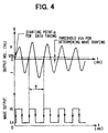
- each of the pickup coils 2b to 5b generates, as shown in Fig. 4, an alternating current signal whose cycle corresponds to a period of the tire torsional vibration.
- the alternating current signals output from the pickup coils 2b to 5b are transferred to a well known electric control unit (hereinafter referred as ECU) having a micro computer composed of CPU, ROM and RAM and waveform shaping circuits.
- ECU electric control unit
- a predetermined data processing including waveform shaping processes of the alternating current signals output from the pickup coils 2b to 5b is executed in the ECU.
- a value fkt of the natural frequency estimated through the data processing is compared with a preset threshold value fot for determining air pressure and, when the value fkt is below the value fot (for example, 32 Hz), the tire air pressure is determined to be abnormal. Then, a warning is generated.
- Results of the data processing are output to a display portion for informing to a drive each tire pressure state of the tires 1a to 1d.
- the display portion may be a display device independently informing to the driver each tire pressure state of the tires 1a to 1d or be a warning lamp for alarming to the driver the abnormal tire air pressure below the predetermined value in at least one of the tires 1a to 1d.
- ECU 6 determines whether the tire air pressure of each of tires 1a to 1d is abnormal based on output of the wheel speed sensors 2 to 5. ECU also outputs drive signals for warning or alarming to the display portion 7.
- ECU 6 is provided with low pass filters 6i to 6l for eliminating noises from signals of the wheel speed sensors 2 to 5 and screening vibration components necessary for estimating the tire air pressure, waveform shaping circuit 6m to 6p for measuring a period T necessary for calculating the natural frequency based on the signals of the wheel speed sensors, natural frequency detecting portions 6a to 6d, and determining portions 6e to 6h for determining the abnormal tire air pressure based on the calculated natural frequency.
- ECU 6 may have respective one or two of the low pass filters, the waveform shaping circuit, the natural frequency detecting portions, and the determining portions and may process sequentially in time one by one or two at the same time with respect to the output signals generated by the wheel speed sensors.
- Fig. 4 shows an example of voltage waveform generated by the wheel speed sensors due to the outside impact (a force causing rotation variation) given to the tires.
- the waveform represents an attenuating vibration caused by the outside impact.
- Fig. 4 also shows an example of a wave output as a result of the waveform shaping through the waveform shaping circuits 6m to 6p provided in ECU 6.
- a voltage Vth shown in Fig. 4, represents a threshold voltage for the waveform shaping, which may be changed according to vehicle models or capacity variations of the wheel speed sensors. As the voltage waveform generated by each of the wheel speed sensors is largely affected by the relative distance between the rotors 2a to 5a and the pickup coils 2b to 5b, the voltage Vth may be adjusted according to a size, large and small, of the voltage waveform generated.
- a starting point ⁇ for taking data in ECU is a point where the output voltage of the pickup coil crosses at first the threshold voltage for determining the waveform shaping.
- a period T shows a time from a point where an output voltage after the waveform shaping rises up to a point where the next output voltage after the waveform shaping rises up.
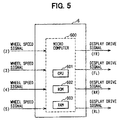
- ECU 6 has a microcomputer 600 that may execute an ordinary processing function.
- the microcomputer 600 operates to achieve functions of the natural frequency detecting portions 6a to 6d and the determining portions 6e to 6h, as mentioned above.
- the microcomputer 600 is composed of a CPU 601 as a processing unit, a ROM 602 to be used as a program memory and a RAM 603 to be used as a data memory.
- the value of the tire natural frequency may be calculated based on the signals of the wheel speed sensors to be generated by the outside impact given to the tires.
- Fig. 6 shows a construction of a brake system as the means for giving the outside impact (force causing the rotation variations) to the tires.
- Fig. 6 shows the brake system (for two wheels).
- the brake system for one of the wheels is composed of a master cylinder 9a, an adjusting valve 9b, a cut valve 9c, a hydraulic pump & motor 9d, pressure control valves 9e1 and 9e2, a reservoir 9f, a wheel cylinder 9g and the rotor 2a integrated with a brake rotor.
- the respective valves are at positions as shown in Fig. 6.
- the adjusting valve 9b is shut off for holding hydraulic pressure on a side of the wheel cylinder when the hydraulic pressure of the wheel cylinder becomes higher than that of the master cylinder in traction control, turning direction control or brake assist control to be made at panic braking or at vacuum booster breakage.
- the cut valve 9c is turned on for allowing to supply brake fluid from the master cylinder 9a to an intake port of the pump in traction control, turning direction control or brake assist control to be made at panic braking or at vacuum booster breakage.
- the pressure control valve 9e1 is communicated when pressure of the wheel cylinder is increased and is interrupted when the pressure of the wheel cylinder is deduced or maintained in ABS control, traction control or turning direction control.
- the pressure control valve 9e2 is interrupted when the pressure of the wheel cylinder is increased or maintained and is communicated when the pressure of the wheel cylinder is reduced.
- the pressure control valves 9e1 and 9e2 are provided for the wheel of the tire 1d, too.
- This brake system is normally called a diagonal conduit system.
- a construction of the brake system for the wheels of the tires 1b and 1c is same as the construction on a side of wheel cylinder with respect to the master cylinder 9a as shown in Fig. 6.
- a state of timing when the hydraulic pressure is changed for giving to the tires the force for causing the rotation variation preferable is either a state that the vehicle stops after an ignition is turned on or a state that the vehicle moves under a predetermined low speed Vso1 after the ignition is turned on.
- the adjusting valve 9b When ECU determines the state mentioned above, the adjusting valve 9b is turned off, the pressure control valve 9e1 is also turned off, and the pump & motor 9d is driven. As a result, a conduit between the adjusting valve 9b and the pressure control valve 9e1 is pressurized by the discharge of the pump. Then, the pressure control valve 9e1 is in a pulsating way turned on and off for a plurality of times by a duty control and the like, so that the hydraulic pressure in the wheel cylinder 9g may be varied as shown in A of Fig 7.
- the pressure control valve 9e2 for pressure reduction may be turned on to reduce the pressure in the wheel cylinder as shown in B of Fig. 7.
- a time during which the hydraulic pressure is applied may be a moment like a pulse or a predetermined short time (for example, pressure is applied 4 times in 2 seconds). Accordingly, the rotors 2a is caused to induce a minute vibration in a rotational direction.
- timing when the hydraulic pressure is applied for causing pressure variation is not limited to be within a period from the time when the ignition is turned on to the time when the vehicle starts, but may fall within a period during which the vehicle stops at a traffic signal or a period during which the vehicle speed is reduced from a predetermined vehicle speed Vso1 until the vehicle completely stops, as shown in B or C of Fig. 7.
- a source for applying hydraulic pressure to the wheel cylinder 9g is not limited to the pump & motor 9d but may be the master cylinder 9a.
- pressure generated by the master cylinder 9a, which is applied to the wheel cylinder 9g may be controlled by the pressure control valve 9e2 when the vehicle speed is below the predetermined vehicle speed Vso1 at a normal braking so that the force for causing the rotation variation may be applied to the rotors 2a to 5a as shown in c of Fig. 7.
- the pressure variation in the master cylinder or in the wheel cylinder may be realized in a manner that the pressure control valve 9e2 is controlled to change from a communicating state to a interrupting state for a predetermined period.
- an accumulator (not shown in Fig. 7) may be used as a hydraulic source to the master cylinder 9g.
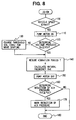
- the process goes to STEP 100 where a determination of the vehicle speed (whether the vehicle substantially stops) is executed. If determined at STEP 100 that the vehicle substantially stops ( ⁇ Vso1), the process goes to STEP 110. Then, the pump & motor 9d, the adjusting valve 9b, the cut valve 9c and the pressure control valves 9e1 and 9e2 in the brake system are operated.
- the Vso1 may be 4 km/s, which means the vehicle speed is substantially zero, in consideration of a signal breakdown capacity of the wheel speed sensors 2 to 5.
- the voltage Vo generated by the pickup coil 2b is compared with the threshold voltage Vth for waveform shaping and, if the voltage Vo is sufficiently larger than the threshold voltage Vth, the process goes to STEP 140 where the vibration period T is measured from the wave form after the waveform shaping (rectangular wave).
- the vibration period T is measured from the wave form after the waveform shaping (rectangular wave).
- resonance vibration phenomena caused by the vibration input may take place.
- a frequency depending on the tire air pressure may be obtained as the resonance vibration frequency, not the natural vibration frequency as mentioned above.
- the threshold voltage Vth is changed to a lower value in order to calculate the value fkt of the natural frequency at STEP 130.
- STEP 150 After calculating the value fkt of the natural frequency, STEP 150 processes to stop the operation of the pump & motor 9d. At STEP 160, the calculated value fkt of the natural frequency is compared with the preset value fot for determining the reduction of the tire air pressure and, if determined that the tire air pressure is abnormal, a signal for warning the reduction of the air pressure is output for alarming to the driver at STEP 170.
- a basic construction of the tire air pressure warning device is same as that disclosed in Fig. 1.
- An inner construction of ECU 6 and means for applying the outside impact (force for causing rotation variation) to the tires are different from those of the first embodiment.
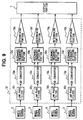
- ECU 10 A controller (hereinafter referred as ECU 10) whose inner construction is different from that of ECU 6 is described with reference to Fig. 9.
- ECU 10 has a portion for determining whether each tire air pressure of the respective tires is abnormal based on each of the wheel speed sensors and a portion for generating a drive signal for displaying to the display portion 7, which are same as those of ECU 6.
- ECU 10 is provided inside thereof with low pass filters 10i to 10l for screening vibration components necessary for estimating the tire air pressure from signals of the wheel speed sensors 2 to 5, AD converters 10m to 10p for converting analog signals of the wheel speed sensors into digital signals, resonance frequency detecting portions 10a to 10d for calculating a resonance frequency in a torsional direction of the tire through a frequency calculation processes based on the digital signals and determining portions 10e to 10h for determining the abnormal tire air pressure based on the calculated resonance frequency.
- low pass filters 10i to 10l for screening vibration components necessary for estimating the tire air pressure from signals of the wheel speed sensors 2 to 5
- AD converters 10m to 10p for converting analog signals of the wheel speed sensors into digital signals
- resonance frequency detecting portions 10a to 10d for calculating a resonance frequency in a torsional direction of the tire through a frequency calculation processes based on the digital signals
- determining portions 10e to 10h for determining the abnormal tire air pressure based on the calculated resonance frequency.
- ECU 10 may have respective one or two of the low pass filters, the AD converters, the resonance frequency detecting portions, and the determining portions and may process sequentially in time one by one or two at the same time with respect to the output signals generated by the wheel speed sensors, which are similar to those of the first embodiment.
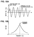
- Fig. 10A shows an example of voltage wave generated by the wheel speed sensors due to the outside impact (a force causing rotation variation) given to the tires.
- a voltage Vtd shown in Fig. 10A, represents a threshold voltage for determining whether the analog signal has an output voltage sufficient enough to obtain the resonance frequency through the subsequent frequency calculation processes.
- a control for applying the outside impact is conducted in a manner that the hydraulic pressure variation is executed in a pulsating way continuously for a plurality of times during a predetermined period.
- the resonance vibration which is sufficiently detectable, may be obtained from the natural frequency depending on the tire air pressure and the outside input of the hydraulic pressure variation.
- Fig. 10B shows an example of the calculated resonance frequency by processing the digital signals of the AD converters in ECU 100 through one of the resonance frequency detecting portions 10a to 10d.
- a starting point for data taking is a point where the output voltage of the pickup coil crosses at first the threshold voltage for determining the output voltage.
- ECU 100 has a microcomputer 600 similar to that shown in Fig. 5 and operates to achieve functions of the resonance frequency detecting portions 10a to 10d and the determining portions 10e to 10h, as mentioned above.
- the microcomputer 600 is composed of a CPU 601 as a processing unit, a ROM 602 to be used as a program memory and a RAM 603 to be used as a data memory.
- Fig. 11 is a flowchart showing a process in ECU 10 for the tire air pressure estimating device according to the second embodiment. As ECU 10 executes identical processes with respect to the respective tires 1a to 1d, the flowchart described below shows a process only relative to the tire 1a.
- the process goes to STEP 200 where a determination of the vehicle speed (whether the vehicle substantially stops) is executed. If determined at STEP 200 that the vehicle substantially stops ( ⁇ Vso1), the process goes to STEP 110.
- STEP 205 determines an engine start in such a manner that engine revolution is larger than a predetermined value and/or a starter is returned from an on state to an off state.
- STEP 210 determines a gearshift change. In a case of automatic shift vehicles, whether a shift lever is moved from a parking range to a drive range.
- STEP 220 determines that a parking brake is turned from an off state to an on state and STEP 230 determines that the parking brake is turned from the on state to the off state.
- STEPs 205 to 230 determine respective existences of various inputs for triggering impacts that cause vibrations of the rotors 2a to 5a integrated with the tires. If the determination of one or more of STEPs 205 to 230 is positive, the process goes to STEP 240. If the determination is negative, that is, if no existence of the input causing the vibration of the rotors 2a to 5a is determined, the process returns to STEP 200.
- STEP 240 determines a largeness of the voltage Vo generated by the pickup coils 2b to 5b to make sure whether the signal is sufficient enough to calculate the accurate resonance frequency at STEP 260.
- STEP 240 determines that the signal has the voltage sufficiently large for the subsequent process, a certain number of digital signals are taken in ECU 10 at STEP 250 as a starting point for data taking that is a point where the output voltage Vo of the pickup coil crosses at first the threshold voltage Vtd.
- the resonance frequency fkt is calculated through a frequency analysis calculation process based on the digital data taken in.
- the frequency analysis calculation process may use calculation methods such as FFT (Fast Fourier Transform) calculation (refer to JP-A-5-133831) and Linear Estimation calculation (refer to JP-A-9-104208).
- the frequency depending on the tire air pressure may be obtained as the natural frequency, not the resonance vibration frequency, in the second embodiment, too, if the vibration input to the tires occurs only for a moment or a very short period in a pulsating way.
- the calculated value fkt of the resonance vibration is compared with the preset value fot for determining the reduction of the tire air pressure and, if determined that the tire air pressure is abnormal, a signal for warning the reduction of the air pressure is output for alarming to the driver at STEP 280.
Landscapes
- Engineering & Computer Science (AREA)
- Mechanical Engineering (AREA)
- Physics & Mathematics (AREA)
- Mathematical Physics (AREA)
- Measuring Fluid Pressure (AREA)
Abstract
Description
Claims (11)
- A tire air pressure warning device in a vehicle provided with a tire (1a to 1d) including a tire axle and outside impact means for giving to the tire an outside impact causing a vibration of the tire axle, comprising:detecting means (2 to 4,6i to 6l, 6m to 6p)for detecting the vibration of the tire axle caused by the outside impact means within a period covering from a time when the vehicle stops to a time when the vehicle moves at a predetermined low speed (steps 100 to 130);calculating means (6a to 6d) for calculating at least one of natural frequency and resonance frequency of the detected vibration (step 140);determining means (6e to 6h) for comparing the at least one of natural frequency and resonance frequency with a preset value and determining a state of tire air pressure of the tire (step 160); andwarning means (7) for informing to a drive the state of the tire air pressure (step 170),
wherein the outside impact means generates a force causing a rotation variation of the tire axle. - A tire air pressure warning device according to claim 1 wherein the force causing the rotation variation of the tire axle is generated by changing a braking force to be applied to the tire axle.
- A tire air pressure warning device according to claim 1 wherein the force causing the rotation variation of the tire axle is generated by changing a force for driving the tire axle.
- A tire air pressure warning device according to claim 1, wherein the detecting means hassignal generating means (2 to 5) for generating time dependent waveform signals reflecting the vibration of the tire axle when the vehicle stops, andvariable threshold means (6i to 6l,6m to 6p) for setting a threshold to the waveform signals so as to generate subsequent output signals whose largeness are sufficient enough for the calculating means to calculate the at least one of natural frequency and resonance frequency of the detected vibration (step 130), whereby a value of the threshold may be varied according to largeness of the waveform signals.
- A tire air pressure warning device according to claim 1, wherein the outside impact means gives to the tire outside impact causing the vibration of the tire axle within a period during which the vehicle stops.
- A tire air pressure warning device according to claim 1, wherein the outside impact means gives to the tire outside impact causing the vibration of the tire axle within a period from a time when an ignition switch is turned on to a time just before the vehicle starts moving.
- A tire air pressure warning device according to claims 1, wherein the outside impact means is a hydraulic brake circuit (9a to 9g) having a wheel cylinder (9g), whereby the outside impact is a hydraulic shock generated in the hydraulic brake circuit and transmitted to the tire via the wheel cylinder.
- A tire air pressure warning device according to claim 7, wherein the hydraulic brake circuit has at least one of a pump 9d) and an accumulator operative for executing at least one of anti-skid control, brake assist control, turning direction control and traction control and the hydraulic shock is generated when pressure in the at least one of a pump and an accumulator is transmitted intentionally in a pulsating way to the wheel cylinder.
- A tire air pressure warning device according to claim 8, wherein the hydraulic brake circuit has a pressure control valve(9b,9e) for controlling the pressure in the wheel cylinder on executing at least one of anti-skid control, brake assist control, turning direction control and traction control, whereby the pressure control valve is intentionally turned on and off for a short period with a repetition adequately selected from single to several times so that the pressure variation in the wheel cylinder may take place in a pulsating way.
- A tire air pressure warning device according to claim 1, wherein the detecting means has a wheel speed sensor (2 to 5)for generating output signals from which the vibration of the tire axle is detected.
- A tire air pressure estimating device according to claim 9, wherein the resonance frequency is constituted by two elements, one of the elements being a resonance frequency component of about 70 hertz in an up & down direction relative to a vehicle body at a normal air pressure of the tire and the other of the elements being a resonance frequency component of about 95 hertz in a back & forth direction relative to the vehicle body at the normal air pressure of the tire.
Applications Claiming Priority (2)
| Application Number | Priority Date | Filing Date | Title |
|---|---|---|---|
| JP24338999 | 1999-08-30 | ||
| JP24338999A JP3565106B2 (en) | 1999-08-30 | 1999-08-30 | Tire pressure alarm |
Publications (3)
| Publication Number | Publication Date |
|---|---|
| EP1080952A2 true EP1080952A2 (en) | 2001-03-07 |
| EP1080952A3 EP1080952A3 (en) | 2004-03-24 |
| EP1080952B1 EP1080952B1 (en) | 2005-10-12 |
Family
ID=17103142
Family Applications (1)
| Application Number | Title | Priority Date | Filing Date |
|---|---|---|---|
| EP00118513A Expired - Lifetime EP1080952B1 (en) | 1999-08-30 | 2000-08-25 | Tire pressure warning device |
Country Status (4)
| Country | Link |
|---|---|
| US (1) | US6450020B1 (en) |
| EP (1) | EP1080952B1 (en) |
| JP (1) | JP3565106B2 (en) |
| DE (1) | DE60030816T8 (en) |
Families Citing this family (22)
| Publication number | Priority date | Publication date | Assignee | Title |
|---|---|---|---|---|
| US7161476B2 (en) | 2000-07-26 | 2007-01-09 | Bridgestone Firestone North American Tire, Llc | Electronic tire management system |
| US8266465B2 (en) | 2000-07-26 | 2012-09-11 | Bridgestone Americas Tire Operation, LLC | System for conserving battery life in a battery operated device |
| JP3641419B2 (en) * | 2000-09-05 | 2005-04-20 | 住友ゴム工業株式会社 | Tire pressure drop alarm device and method |
| JP2002172920A (en) * | 2000-09-29 | 2002-06-18 | Toyota Central Res & Dev Lab Inc | Tire pressure estimation device |
| DE60205340T2 (en) * | 2001-02-26 | 2006-03-23 | Toyota Jidosha Kabushiki Kaisha, Toyota | TIRE STATE APPRAISAL APPARATUS AND DEVICE FOR DETECTING AN ABNORMAL TIRE CONDITION |
| DE60107670T2 (en) * | 2001-02-27 | 2005-10-06 | Sumida Corp. | LEAD-FREE SOLDERING ALLOY AND THEIR USE IN ELECTRONIC COMPONENTS |
| US20040102880A1 (en) * | 2001-10-17 | 2004-05-27 | Brown James K | System for monitoring vehicle wheel vibration |
| US6714858B2 (en) * | 2002-07-30 | 2004-03-30 | General Motors Corporation | On road corner dynamic balancing for vehicle wheels |
| DE10331585A1 (en) * | 2003-07-08 | 2005-03-31 | Continental Teves Ag & Co. Ohg | Method for determining the internal pressure of a vehicle tire |
| WO2005056312A1 (en) * | 2003-12-12 | 2005-06-23 | Bridgestone Corporation | Device and method for detecting abnormality of rotating body |
| US6993449B2 (en) * | 2004-01-31 | 2006-01-31 | Continental Teves, Inc. | Tire pressure loss detection |
| JPWO2011040019A1 (en) * | 2009-09-30 | 2013-02-21 | パナソニック株式会社 | Tire condition detecting apparatus and tire condition detecting method |
| JP5531265B2 (en) * | 2010-10-12 | 2014-06-25 | パナソニック株式会社 | Tire condition detecting apparatus and tire condition detecting method |
| US9121790B2 (en) | 2011-01-28 | 2015-09-01 | GM Global Technology Operations LLC | Methods and systems for evaluating tire properties |
| US9329103B2 (en) | 2011-01-28 | 2016-05-03 | GM Global Technology Operations LLC | Methods and systems for characterizing vehicle tires |
| WO2014057609A1 (en) * | 2012-10-11 | 2014-04-17 | 株式会社ブリヂストン | Tire pressure warning system |
| JP2014076748A (en) * | 2012-10-11 | 2014-05-01 | Bridgestone Corp | Tire internal pressure alarm system |
| KR101373151B1 (en) * | 2012-12-18 | 2014-03-20 | 현대오트론 주식회사 | Apparatus and method for detecting vehicle tire condition |
| US8868290B2 (en) | 2013-01-04 | 2014-10-21 | Infineon Technologies Ag | Wheel speed sensor with support for indirect tire pressure monitoring |
| DE102016005126B3 (en) * | 2016-04-28 | 2017-06-01 | Audi Ag | Method for controlling a pressure |
| US10352262B2 (en) | 2016-09-22 | 2019-07-16 | Hyundai Motor Company | Speed limiting device, vehicle having the same and method for controlling the same |
| FR3067290B1 (en) * | 2017-06-08 | 2019-07-05 | Renault S.A.S. | METHOD FOR DIAGNOSING THE INFLATION CONDITION OF A VEHICLE TIRE |
Citations (2)
| Publication number | Priority date | Publication date | Assignee | Title |
|---|---|---|---|---|
| JPH05133831A (en) | 1991-11-11 | 1993-05-28 | Nippondenso Co Ltd | Tire air pressure detection device |
| JPH09104208A (en) | 1995-08-04 | 1997-04-22 | Denso Corp | Tire pressure estimation device |
Family Cites Families (7)
| Publication number | Priority date | Publication date | Assignee | Title |
|---|---|---|---|---|
| US5497657A (en) | 1991-11-11 | 1996-03-12 | Nippondenso Co., Ltd. | Tire air pressure detecting device |
| US5553491A (en) * | 1991-11-11 | 1996-09-10 | Nippondenso Co., Ltd. | Tire air pressure detecting device |
| JP3289375B2 (en) * | 1993-03-24 | 2002-06-04 | 株式会社デンソー | VEHICLE VEHICLE VEHICLE ESTIMATION DEVICE AND TIRE CONDITION DETECTOR USING ESTIMATED VEHICLE VEHICLE VEHICLE |
| DE69510287T2 (en) * | 1994-09-09 | 2000-03-23 | Denso Corp., Kariya | Pneumatic tire pressure gauge |
| JP3760479B2 (en) * | 1995-06-05 | 2006-03-29 | 株式会社デンソー | Braking state detection device and vehicle control device |
| JPH09126932A (en) * | 1995-10-31 | 1997-05-16 | Aisin Seiki Co Ltd | Tire air pressure detection method and air pressure detection device |
| US6092028A (en) * | 1997-08-08 | 2000-07-18 | Densco Corporation | Apparatus for estimating tire air pressure |
-
1999
- 1999-08-30 JP JP24338999A patent/JP3565106B2/en not_active Expired - Fee Related
-
2000
- 2000-08-25 DE DE60030816T patent/DE60030816T8/en not_active Expired - Fee Related
- 2000-08-25 EP EP00118513A patent/EP1080952B1/en not_active Expired - Lifetime
- 2000-08-28 US US09/649,817 patent/US6450020B1/en not_active Expired - Fee Related
Patent Citations (2)
| Publication number | Priority date | Publication date | Assignee | Title |
|---|---|---|---|---|
| JPH05133831A (en) | 1991-11-11 | 1993-05-28 | Nippondenso Co Ltd | Tire air pressure detection device |
| JPH09104208A (en) | 1995-08-04 | 1997-04-22 | Denso Corp | Tire pressure estimation device |
Also Published As
| Publication number | Publication date |
|---|---|
| DE60030816T2 (en) | 2007-01-25 |
| DE60030816D1 (en) | 2006-11-02 |
| JP2001063327A (en) | 2001-03-13 |
| EP1080952A3 (en) | 2004-03-24 |
| JP3565106B2 (en) | 2004-09-15 |
| DE60030816T8 (en) | 2007-05-31 |
| US6450020B1 (en) | 2002-09-17 |
| EP1080952B1 (en) | 2005-10-12 |
Similar Documents
| Publication | Publication Date | Title |
|---|---|---|
| EP1080952B1 (en) | Tire pressure warning device | |
| US8899033B2 (en) | Brake booster leak detection system | |
| US7461713B2 (en) | Tire protecting apparatus | |
| JPH11512053A (en) | Tire pressure monitoring device | |
| KR20010113042A (en) | Method for the automatic operation of a tire inflation device for motor vehicles | |
| JP2002137658A (en) | Vehicle control and / or driver notification method and device for tire pressure loss | |
| GB2310731A (en) | Control of the approach of a vehicle to an obstruction | |
| CN113147279A (en) | Automatic positioning method and system for automobile tire pressure monitoring, vehicle and storage medium | |
| JP2003531763A (en) | Misalignment detection system for automotive steering system | |
| US7092809B2 (en) | Method and system for controlling braking equipment | |
| JP2002527290A (en) | Method and apparatus for monitoring braking in an anti-lock or electronic braking system | |
| CN118654905A (en) | Air suspension system health monitoring method, system and vehicle | |
| CN109476290A (en) | Vehicles with Start Assist | |
| CN106414190B (en) | Vehicle brake control device | |
| US20230041676A1 (en) | Method for controlling brake fluid pressure using esc system | |
| JP4028727B2 (en) | Control system with sensor with self-diagnosis function | |
| KR100305830B1 (en) | Oscillation control device and oscillation control method on hill | |
| JPH0789428A (en) | Anti-skid controller | |
| JP2001199320A (en) | Method and apparatus for operating vehicle slip control brake device | |
| WO1994004384A1 (en) | Throttle traction control for automotive vehicle | |
| JPH0542862A (en) | Inter-vehicle distance control device | |
| GB2297619A (en) | Method of predicting vehicle standstill | |
| JP2002145046A (en) | Automotive brake failure diagnosis device | |
| CN100532876C (en) | Method and device for identifying clutch slip point | |
| JP2004516981A (en) | System and method for monitoring tire characteristics |
Legal Events
| Date | Code | Title | Description |
|---|---|---|---|
| PUAI | Public reference made under article 153(3) epc to a published international application that has entered the european phase |
Free format text: ORIGINAL CODE: 0009012 |
|
| AK | Designated contracting states |
Kind code of ref document: A2 Designated state(s): AT BE CH CY DE DK ES FI FR GB GR IE IT LI LU MC NL PT SE |
|
| AX | Request for extension of the european patent |
Free format text: AL;LT;LV;MK;RO;SI |
|
| PUAL | Search report despatched |
Free format text: ORIGINAL CODE: 0009013 |
|
| AK | Designated contracting states |
Kind code of ref document: A3 Designated state(s): AT BE CH CY DE DK ES FI FR GB GR IE IT LI LU MC NL PT SE |
|
| AX | Request for extension of the european patent |
Extension state: AL LT LV MK RO SI |
|
| 17P | Request for examination filed |
Effective date: 20040420 |
|
| AKX | Designation fees paid |
Designated state(s): DE FR GB |
|
| GRAP | Despatch of communication of intention to grant a patent |
Free format text: ORIGINAL CODE: EPIDOSNIGR1 |
|
| GRAS | Grant fee paid |
Free format text: ORIGINAL CODE: EPIDOSNIGR3 |
|
| GRAA | (expected) grant |
Free format text: ORIGINAL CODE: 0009210 |
|
| AK | Designated contracting states |
Kind code of ref document: B1 Designated state(s): DE FR GB |
|
| REG | Reference to a national code |
Ref country code: GB Ref legal event code: FG4D |
|
| RIN1 | Information on inventor provided before grant (corrected) |
Inventor name: TAGUCHI, TAKEYASU,C/O DENSO CORPORATION Inventor name: SAWADA, MAMORU,C/O DENSO CORPORATION Inventor name: INOUE, YUICHI,C/O DENSO CORPORATION Inventor name: NAITO, TOSHIHARU,C/O DENSO CORPORATION |
|
| ET | Fr: translation filed | ||
| PLBE | No opposition filed within time limit |
Free format text: ORIGINAL CODE: 0009261 |
|
| STAA | Information on the status of an ep patent application or granted ep patent |
Free format text: STATUS: NO OPPOSITION FILED WITHIN TIME LIMIT |
|
| 26N | No opposition filed |
Effective date: 20060713 |
|
| REG | Reference to a national code |
Ref country code: GB Ref legal event code: 746 Effective date: 20060906 |
|
| REF | Corresponds to: |
Ref document number: 60030816 Country of ref document: DE Date of ref document: 20061102 Kind code of ref document: P |
|
| PGFP | Annual fee paid to national office [announced via postgrant information from national office to epo] |
Ref country code: DE Payment date: 20070823 Year of fee payment: 8 |
|
| PGFP | Annual fee paid to national office [announced via postgrant information from national office to epo] |
Ref country code: GB Payment date: 20070822 Year of fee payment: 8 |
|
| PGFP | Annual fee paid to national office [announced via postgrant information from national office to epo] |
Ref country code: FR Payment date: 20070808 Year of fee payment: 8 |
|
| GBPC | Gb: european patent ceased through non-payment of renewal fee |
Effective date: 20080825 |
|
| REG | Reference to a national code |
Ref country code: FR Ref legal event code: ST Effective date: 20090430 |
|
| PG25 | Lapsed in a contracting state [announced via postgrant information from national office to epo] |
Ref country code: DE Free format text: LAPSE BECAUSE OF NON-PAYMENT OF DUE FEES Effective date: 20090303 Ref country code: FR Free format text: LAPSE BECAUSE OF NON-PAYMENT OF DUE FEES Effective date: 20080901 |
|
| PG25 | Lapsed in a contracting state [announced via postgrant information from national office to epo] |
Ref country code: GB Free format text: LAPSE BECAUSE OF NON-PAYMENT OF DUE FEES Effective date: 20080825 |