EP1080871A1 - Fabricating graded index plastic optical fibers - Google Patents
Fabricating graded index plastic optical fibers Download PDFInfo
- Publication number
- EP1080871A1 EP1080871A1 EP00307170A EP00307170A EP1080871A1 EP 1080871 A1 EP1080871 A1 EP 1080871A1 EP 00307170 A EP00307170 A EP 00307170A EP 00307170 A EP00307170 A EP 00307170A EP 1080871 A1 EP1080871 A1 EP 1080871A1
- Authority
- EP
- European Patent Office
- Prior art keywords
- optical fiber
- plastic optical
- dopant
- diffusion
- temperature
- Prior art date
- Legal status (The legal status is an assumption and is not a legal conclusion. Google has not performed a legal analysis and makes no representation as to the accuracy of the status listed.)
- Granted
Links
- 239000013308 plastic optical fiber Substances 0.000 title abstract description 43
- 239000002019 doping agent Substances 0.000 claims abstract description 42
- 238000009792 diffusion process Methods 0.000 claims abstract description 25
- 230000005540 biological transmission Effects 0.000 claims abstract description 20
- 239000000463 material Substances 0.000 claims abstract description 15
- 238000012360 testing method Methods 0.000 claims abstract description 12
- 238000010438 heat treatment Methods 0.000 claims abstract description 9
- 239000013307 optical fiber Substances 0.000 claims description 55
- 238000000034 method Methods 0.000 claims description 26
- 238000005253 cladding Methods 0.000 claims description 5
- 239000006185 dispersion Substances 0.000 claims description 2
- 238000005259 measurement Methods 0.000 claims 1
- 239000004811 fluoropolymer Substances 0.000 description 20
- 229920002313 fluoropolymer Polymers 0.000 description 20
- 239000000835 fiber Substances 0.000 description 10
- 238000004519 manufacturing process Methods 0.000 description 7
- 239000000178 monomer Substances 0.000 description 7
- 238000001125 extrusion Methods 0.000 description 6
- 238000002156 mixing Methods 0.000 description 4
- 229920000642 polymer Polymers 0.000 description 4
- 238000006116 polymerization reaction Methods 0.000 description 4
- 239000002904 solvent Substances 0.000 description 4
- 229920001169 thermoplastic Polymers 0.000 description 4
- 238000002844 melting Methods 0.000 description 3
- 239000004416 thermosoftening plastic Substances 0.000 description 3
- 230000015572 biosynthetic process Effects 0.000 description 2
- 230000007423 decrease Effects 0.000 description 2
- 230000003247 decreasing effect Effects 0.000 description 2
- 238000010586 diagram Methods 0.000 description 2
- 230000009477 glass transition Effects 0.000 description 2
- 229920002100 high-refractive-index polymer Polymers 0.000 description 2
- 239000000155 melt Substances 0.000 description 2
- 238000002074 melt spinning Methods 0.000 description 2
- 230000008018 melting Effects 0.000 description 2
- 239000000203 mixture Substances 0.000 description 2
- 238000000465 moulding Methods 0.000 description 2
- 230000003287 optical effect Effects 0.000 description 2
- 229920000058 polyacrylate Polymers 0.000 description 2
- 239000004677 Nylon Substances 0.000 description 1
- 239000004697 Polyetherimide Substances 0.000 description 1
- 229920006311 Urethane elastomer Polymers 0.000 description 1
- 230000004913 activation Effects 0.000 description 1
- 239000011248 coating agent Substances 0.000 description 1
- 238000000576 coating method Methods 0.000 description 1
- 229920001577 copolymer Polymers 0.000 description 1
- 229920006037 cross link polymer Polymers 0.000 description 1
- 238000004132 cross linking Methods 0.000 description 1
- 238000003618 dip coating Methods 0.000 description 1
- 238000010894 electron beam technology Methods 0.000 description 1
- 239000003822 epoxy resin Substances 0.000 description 1
- UHESRSKEBRADOO-UHFFFAOYSA-N ethyl carbamate;prop-2-enoic acid Chemical compound OC(=O)C=C.CCOC(N)=O UHESRSKEBRADOO-UHFFFAOYSA-N 0.000 description 1
- 230000008020 evaporation Effects 0.000 description 1
- 238000001704 evaporation Methods 0.000 description 1
- 239000011521 glass Substances 0.000 description 1
- LNEPOXFFQSENCJ-UHFFFAOYSA-N haloperidol Chemical compound C1CC(O)(C=2C=CC(Cl)=CC=2)CCN1CCCC(=O)C1=CC=C(F)C=C1 LNEPOXFFQSENCJ-UHFFFAOYSA-N 0.000 description 1
- HCDGVLDPFQMKDK-UHFFFAOYSA-N hexafluoropropylene Chemical group FC(F)=C(F)C(F)(F)F HCDGVLDPFQMKDK-UHFFFAOYSA-N 0.000 description 1
- 239000011261 inert gas Substances 0.000 description 1
- 239000007788 liquid Substances 0.000 description 1
- 229920001778 nylon Polymers 0.000 description 1
- 229920002492 poly(sulfone) Polymers 0.000 description 1
- 229920000647 polyepoxide Polymers 0.000 description 1
- 229920001601 polyetherimide Polymers 0.000 description 1
- 230000000379 polymerizing effect Effects 0.000 description 1
- KCTAWXVAICEBSD-UHFFFAOYSA-N prop-2-enoyloxy prop-2-eneperoxoate Chemical compound C=CC(=O)OOOC(=O)C=C KCTAWXVAICEBSD-UHFFFAOYSA-N 0.000 description 1
- 230000009257 reactivity Effects 0.000 description 1
- 229920002379 silicone rubber Polymers 0.000 description 1
- BFKJFAAPBSQJPD-UHFFFAOYSA-N tetrafluoroethene Chemical group FC(F)=C(F)F BFKJFAAPBSQJPD-UHFFFAOYSA-N 0.000 description 1
Images


Classifications
-
- G—PHYSICS
- G02—OPTICS
- G02B—OPTICAL ELEMENTS, SYSTEMS OR APPARATUS
- G02B6/00—Light guides; Structural details of arrangements comprising light guides and other optical elements, e.g. couplings
- G02B6/02—Optical fibres with cladding with or without a coating
- G02B6/02033—Core or cladding made from organic material, e.g. polymeric material
- G02B6/02038—Core or cladding made from organic material, e.g. polymeric material with core or cladding having graded refractive index
-
- B—PERFORMING OPERATIONS; TRANSPORTING
- B29—WORKING OF PLASTICS; WORKING OF SUBSTANCES IN A PLASTIC STATE IN GENERAL
- B29C—SHAPING OR JOINING OF PLASTICS; SHAPING OF MATERIAL IN A PLASTIC STATE, NOT OTHERWISE PROVIDED FOR; AFTER-TREATMENT OF THE SHAPED PRODUCTS, e.g. REPAIRING
- B29C48/00—Extrusion moulding, i.e. expressing the moulding material through a die or nozzle which imparts the desired form; Apparatus therefor
- B29C48/03—Extrusion moulding, i.e. expressing the moulding material through a die or nozzle which imparts the desired form; Apparatus therefor characterised by the shape of the extruded material at extrusion
- B29C48/05—Filamentary, e.g. strands
-
- B—PERFORMING OPERATIONS; TRANSPORTING
- B29—WORKING OF PLASTICS; WORKING OF SUBSTANCES IN A PLASTIC STATE IN GENERAL
- B29D—PRODUCING PARTICULAR ARTICLES FROM PLASTICS OR FROM SUBSTANCES IN A PLASTIC STATE
- B29D11/00—Producing optical elements, e.g. lenses or prisms
- B29D11/00663—Production of light guides
- B29D11/00682—Production of light guides with a refractive index gradient
-
- B—PERFORMING OPERATIONS; TRANSPORTING
- B29—WORKING OF PLASTICS; WORKING OF SUBSTANCES IN A PLASTIC STATE IN GENERAL
- B29D—PRODUCING PARTICULAR ARTICLES FROM PLASTICS OR FROM SUBSTANCES IN A PLASTIC STATE
- B29D11/00—Producing optical elements, e.g. lenses or prisms
- B29D11/00663—Production of light guides
- B29D11/00721—Production of light guides involving preforms for the manufacture of light guides
-
- B—PERFORMING OPERATIONS; TRANSPORTING
- B29—WORKING OF PLASTICS; WORKING OF SUBSTANCES IN A PLASTIC STATE IN GENERAL
- B29C—SHAPING OR JOINING OF PLASTICS; SHAPING OF MATERIAL IN A PLASTIC STATE, NOT OTHERWISE PROVIDED FOR; AFTER-TREATMENT OF THE SHAPED PRODUCTS, e.g. REPAIRING
- B29C48/00—Extrusion moulding, i.e. expressing the moulding material through a die or nozzle which imparts the desired form; Apparatus therefor
Definitions
- This invention relates to the fabrication of optical fiber.
- a dopant is so distributed in a fluoropolymer as to have a concentration gradient in the direction from the center to the periphery.
- the dopant is a material having a higher refractive index than the fluoropolymer, and the dopant is so distributed as to have a concentration gradient such that the concentration of the dopant decreases in the direction from the center of the optical fiber to the periphery.
- a graded refractive index optical fiber is produced by arranging the dopant at the center and diffusing the dopant toward the periphery.
- a graded refractive index optical fiber is formed wherein the dopant is a material having a lower refractive index than the fluoropolymer, and the dopant is so distributed as to have a concentration gradient that the concentration of the dopant decreases in the direction from the periphery of the optical fibers to the center, is also useful.
- a graded refractive index optical fiber is produced by diffusing the dopant from the periphery toward the center.
- a first method comprises melting the fluoropolymer, injecting the dopant or a fluoropolymer containing the dopant at the center of the melt of the fluoropolymer, and then molding the melt while or after diffusing the dopant.
- the dopant may be injected at the center not only so as to form only one layer but also so as to form multiple layers.
- the molding is carried out by melt-extrusion, which is suitable for forming a rod-like body material such as a preform of an optical fiber, or by melt-spinning, which is suitable for forming an optical fiber.
- a second method comprises dip-coating the dopant or the fluoropolymer containing the dopant on a core formed from the fluoropolymer by melt spinning or drawing.
- a third method comprises forming a hollow tube of the fluoropolymer by using a rotating glass tube or the like, filling in the polymer tube with a monomer phase which gives the dopant or the fluoropolymer which contains the dopant, and then polymerizing the monomer phase while rotating the polymer tube at a low speed.
- the tube of the fluoropolymer swells up in the monomer phase and forms a gel phase, and the monomer molecules are polymerized while preferentially diffusing in the gel phase.
- a fourth method wherein two kinds of monomers with different reactivities, one of which is a monomer which forms the fluoropolymer, and the other is a monomer which forms the dopant, are used, and the polymerization reaction is carried out so that the compositional proportion of the resulting fluoropolymer to the resulting dopant varies continuously in the direction from the periphery to the center.
- a fifth method comprises hot-drawing or melt-extruding a mixture of the fluoropolymer and the dopant obtained by homogeneously mixing them or by homogeneously mixing them in a solvent and then removing the solvent by means of evaporation, into fibers, and then (or immediately after the formation of the fibers) bringing the fibers into contact with an inert gas under heating to evaporate the dopant from the surface and thereby forming a graded refractive index.
- a method wherein after the formation of the fibers, the fibers are immersed in a solvent which does not dissolve the fluoropolymer but dissolves the dopant so as to dissolve out the dopant from the surface of the fibers so that a graded refractive index is formed.
- a sixth method comprises coating a rod or a fiber of the fluoropolymer with only the dopant which has a smaller refractive index than the fluoropolymer or with a mixture of the fluoropolymer and the dopant, and then diffusing the dopant by heating to form a graded refractive index.
- a seventh method comprises mixing a high-refractive-index polymer and a low-refractive-index polymer by hot-melting or in a state of a solution containing a solvent, and diffusing them in each other while (or after) multilayer-excluding in a state that each has a different mixing ratio, to eventually obtain a fiber having a graded refractive index.
- the high-refractive-index polymer may be the fluoropolymer
- the low-refractive-index polymer may be the dopant.
- optical transmission bandwidth is determined by a post-manufacturing test step after the cladding and buffer have been added to the fabricated core of the optical fiber and all diffusion processes are completed. If the transmission bandwidth does not meet the required specifications, the optical fiber must be discarded. This represents a significant problem in the prior art method of fabricating plastic optical fiber.
- a departure in the art is achieved by an apparatus and method for fabricating graded index plastic optical fiber by diffusing a high molecular weight dopant within a step index plastic optical fiber after the step index plastic optical fiber has been drawn from a preform using a conventional draw tower in a first embodiment.
- the step index plastic optical fiber may be fabricated by extruding one material circumferentially around another material, e.g., by use of a concentric nozzle.
- the dopant is diffused after the drawing or extruding of the step index plastic optical fiber by heating the plastic optical fiber to a temperature that causes a high rate of diffusion state while measuring the transmission bandwidth of the plastic optical fiber. When the predetermined specified transmission bandwidth is measured, the plastic optical fiber is immediately returned to an ambient temperature.
- the plastic optical fiber is gradually heated to an equilibrium temperature that is just below the temperature required to produce the high rate of diffusion state. Once the equilibrium temperature has been achieved, additional heating is carried out to raise the temperature to that required to produce the high rate of diffusion and the transmission bandwidth is tested. The diffusion continues until the specified transmission bandwidth is reached. Also, when the plastic optical fiber is initially drawn from the preform, or is initially formed by extrusion, the resulting core and outer cladding are covered with a buffer material that will remain substantially undistorted at the temperature required for a high rate of diffusion.
- the preform is initially heated for an amount of time that will allow the diffusion process to be partially completed. After the plastic optical fiber has been drawn, the remaining diffusion is accomplished by testing for the specified transmission bandwidth. The plastic optical fiber is returned to the ambient temperature when the specified transmission bandwidth is achieved.
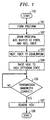
- FIG. 1 illustrates the steps for fabricating plastic optical fiber in accordance with the first embodiment.
- block 101 forms the preform with the dopant.
- block 102 draws the preform to the proper diameter for a step index plastic optical fiber, adds the buffer material to the step index plastic optical fiber, and places the step index plastic optical fiber on a reel.
- the reel of step index optical fiber is placed in an oven at ambient temperature, the oven is then heated until the optical fiber reaches an equilibrium temperature which is slightly less than the temperature required to place the step index plastic optical fiber in the high rate of diffusion state that causes a graded index plastic optical fiber to be formed.
- block 104 causes the temperature of the oven to be raised to the temperature required for the high rate of diffusion and transfers control to decision block 106.
- the transmission bandwidth is measured to determine if the necessary bandwidth has been achieved, if the answer is no, the bandwidth continues to be measured until it reaches the specified level.
- control is transferred to block 107 where the graded index optical fiber is returned to the ambient temperature either by removing the reel of optical fiber from the oven or rapidly decreasing the temperature of the oven.
- block 108 which is the termination of the fabrication process.
- the step index plastic optical fiber is not placed on a reel before heating but rather that the resulting graded plastic optical fiber is placed on a reel. If the step index plastic optical fiber is formed by extrusion rather than drawn from a preform, steps of blocks 101 and 102 are combined into a step of extruding and reeling the step index plastic optical fiber.
- the buffer material which covers the cladding and the core of the optical fiber may advantageously be a thermoplastic polymer having a high melting temperature or glass transition temperature, above the temperature at which the dopant diffusion process is carried out.
- the thermoplastic buffer may be applied to optical fiber during, or subsequent to, the drawing process. Suitable processes for applying the thermoplastic buffer include melt extrusion or drawing from a melted tube which surrounds the preform or fiber.
- buffer material may be a crosslinked polymer which is applied to the drawn optical fiber in a liquid prepolymer state, and solidified using thermal, UV or electron beam activation to initiate a rapid crosslinking polymerization reaction. Because such a buffer possesses a permanent network structure, it retains its shape even when heated above its glass transition temperature.
- thermoplastic buffer materials are nylon, polyetherimide, polysulfone, copolymers of tetrafluoroethylene and hexafluoropropylene and amorphous fluoropolymers.
- crosslinked buffer materials are silicone elastomers, urethane acrylate polymers, epoxy resins, epoxy acrylate polymers and urethane elastomers.
- FIG. 2 illustrates the steps for fabricating plastic optical fiber in accordance with the second embodiment.
- block 201 forms the preform with the dopant. Addition, block 201 partially diffuses the dopant for a predetermined amount of time.
- block 202 draws the preform to the proper diameter for the plastic optical fiber, adds the buffer material to the optical fiber, and places the optical fiber on a reel.
- the reel of optical fiber is placed in an oven at ambient temperature, the oven is then heated until the optical fiber reaches an equilibrium temperature which is slightly less than the temperature required to place the optical fiber in the high rate of diffusion state.
- block 204 causes the temperature of the oven to be raised to the temperature required for the high rate of diffusion and transfers control to decision block 206.
- the transmission bandwidth is measured to determine if the necessary bandwidth has been achieved, if the answer is no, the bandwidth continues to be measured until it reaches the specified level.
- control is transferred to block 207 whereby the optical fiber is returned to the ambient temperature either by removing the reel of optical fiber from the oven or rapidly decreasing the temperature of the oven.
- block 208 which is the termination of the fabrication process.
- blocks 201 and 202 are merged into a step of extruding and reeling the initial plastic optical fiber.
- FIG. 3 illustrates the apparatus necessary for implementing both embodiments when using preforms.
- Apparatus 301 is utilized to form the preforms
- drawing tower 302 is utilized to form the optical fiber from the preform and to enclose the optical fiber in a buffer.
- oven 303 which may be manually or automatically controlled. If oven 303 is automatically controlled, then the output at test set 304 is used by the automatic controller to determine when to reduce the temperature on reel 306.
- Test set 304 may be a pulse dispersion test set.
- test set 304 may be a differential mode delay test set or may be a test set that simply measures the bit error rate of a high-speed optical serial link.
- FIG. 4 illustrates the apparatus necessary for implementing both embodiments when the initial plastic optical fiber is fabricated by extrusion.
- Apparatus 401 is utilized to extrude the optical fiber, to enclose the optical fiber in a buffer and to form onto reel 406. After the reel of optical fiber is formed in apparatus 401, it is placed in oven 403 which may be manually or automatically controlled. If oven 403 is automatically controlled, then the output at test set 404 is used by the automatic controller to determine when to reduce the temperature on reel 406.
- Apparatus 401 is disclosed in FIG. 1 of U.S. Patent No. 5,593,621.
Landscapes
- Engineering & Computer Science (AREA)
- Mechanical Engineering (AREA)
- Health & Medical Sciences (AREA)
- Manufacturing & Machinery (AREA)
- Ophthalmology & Optometry (AREA)
- Physics & Mathematics (AREA)
- General Physics & Mathematics (AREA)
- Optics & Photonics (AREA)
- Extrusion Moulding Of Plastics Or The Like (AREA)
- Optical Fibers, Optical Fiber Cores, And Optical Fiber Bundles (AREA)
Abstract
Description
- This invention relates to the fabrication of optical fiber.
- In the prior art, fabrication of a graded-refractive-index optical fiber is well known. For example, U.S. Patent No. 5,760,139 and U.S. Patent No. 5,783,636 disclose seven methods for fabricating a graded-refractive-index optical fiber. In such an optical fiber, a dopant is so distributed in a fluoropolymer as to have a concentration gradient in the direction from the center to the periphery. Preferably, it is an optical fiber wherein the dopant is a material having a higher refractive index than the fluoropolymer, and the dopant is so distributed as to have a concentration gradient such that the concentration of the dopant decreases in the direction from the center of the optical fiber to the periphery. Hence, a graded refractive index optical fiber is produced by arranging the dopant at the center and diffusing the dopant toward the periphery. In other cases, a graded refractive index optical fiber is formed wherein the dopant is a material having a lower refractive index than the fluoropolymer, and the dopant is so distributed as to have a concentration gradient that the concentration of the dopant decreases in the direction from the periphery of the optical fibers to the center, is also useful. Hence, a graded refractive index optical fiber is produced by diffusing the dopant from the periphery toward the center.
- The above-referenced patents disclose the following seven methods for fabricating graded index plastic optical fiber. A first method comprises melting the fluoropolymer, injecting the dopant or a fluoropolymer containing the dopant at the center of the melt of the fluoropolymer, and then molding the melt while or after diffusing the dopant. In this case, the dopant may be injected at the center not only so as to form only one layer but also so as to form multiple layers. The molding is carried out by melt-extrusion, which is suitable for forming a rod-like body material such as a preform of an optical fiber, or by melt-spinning, which is suitable for forming an optical fiber.
- A second method comprises dip-coating the dopant or the fluoropolymer containing the dopant on a core formed from the fluoropolymer by melt spinning or drawing.
- A third method comprises forming a hollow tube of the fluoropolymer by using a rotating glass tube or the like, filling in the polymer tube with a monomer phase which gives the dopant or the fluoropolymer which contains the dopant, and then polymerizing the monomer phase while rotating the polymer tube at a low speed. In the case of interfacial gel polymerization, at the polymerization step, the tube of the fluoropolymer swells up in the monomer phase and forms a gel phase, and the monomer molecules are polymerized while preferentially diffusing in the gel phase. A fourth method wherein two kinds of monomers with different reactivities, one of which is a monomer which forms the fluoropolymer, and the other is a monomer which forms the dopant, are used, and the polymerization reaction is carried out so that the compositional proportion of the resulting fluoropolymer to the resulting dopant varies continuously in the direction from the periphery to the center.
- A fifth method comprises hot-drawing or melt-extruding a mixture of the fluoropolymer and the dopant obtained by homogeneously mixing them or by homogeneously mixing them in a solvent and then removing the solvent by means of evaporation, into fibers, and then (or immediately after the formation of the fibers) bringing the fibers into contact with an inert gas under heating to evaporate the dopant from the surface and thereby forming a graded refractive index. Or, a method wherein after the formation of the fibers, the fibers are immersed in a solvent which does not dissolve the fluoropolymer but dissolves the dopant so as to dissolve out the dopant from the surface of the fibers so that a graded refractive index is formed.
- A sixth method comprises coating a rod or a fiber of the fluoropolymer with only the dopant which has a smaller refractive index than the fluoropolymer or with a mixture of the fluoropolymer and the dopant, and then diffusing the dopant by heating to form a graded refractive index.
- A seventh method comprises mixing a high-refractive-index polymer and a low-refractive-index polymer by hot-melting or in a state of a solution containing a solvent, and diffusing them in each other while (or after) multilayer-excluding in a state that each has a different mixing ratio, to eventually obtain a fiber having a graded refractive index. In this case, the high-refractive-index polymer may be the fluoropolymer, and the low-refractive-index polymer may be the dopant.
- In all of the above fabrication methods, optical transmission bandwidth is determined by a post-manufacturing test step after the cladding and buffer have been added to the fabricated core of the optical fiber and all diffusion processes are completed. If the transmission bandwidth does not meet the required specifications, the optical fiber must be discarded. This represents a significant problem in the prior art method of fabricating plastic optical fiber.
- A departure in the art is achieved by an apparatus and method for fabricating graded index plastic optical fiber by diffusing a high molecular weight dopant within a step index plastic optical fiber after the step index plastic optical fiber has been drawn from a preform using a conventional draw tower in a first embodiment. Also, the step index plastic optical fiber may be fabricated by extruding one material circumferentially around another material, e.g., by use of a concentric nozzle. The dopant is diffused after the drawing or extruding of the step index plastic optical fiber by heating the plastic optical fiber to a temperature that causes a high rate of diffusion state while measuring the transmission bandwidth of the plastic optical fiber. When the predetermined specified transmission bandwidth is measured, the plastic optical fiber is immediately returned to an ambient temperature. Advantageously, the plastic optical fiber is gradually heated to an equilibrium temperature that is just below the temperature required to produce the high rate of diffusion state. Once the equilibrium temperature has been achieved, additional heating is carried out to raise the temperature to that required to produce the high rate of diffusion and the transmission bandwidth is tested. The diffusion continues until the specified transmission bandwidth is reached. Also, when the plastic optical fiber is initially drawn from the preform, or is initially formed by extrusion, the resulting core and outer cladding are covered with a buffer material that will remain substantially undistorted at the temperature required for a high rate of diffusion.
- In a second embodiment of the invention, the preform is initially heated for an amount of time that will allow the diffusion process to be partially completed. After the plastic optical fiber has been drawn, the remaining diffusion is accomplished by testing for the specified transmission bandwidth. The plastic optical fiber is returned to the ambient temperature when the specified transmission bandwidth is achieved.
- Other and further aspects of the present invention will become apparent during the course of the following description and by reference to the accompanying drawing.
-
- FIG. 1 illustrates, in flowchart form, steps for fabricating plastic optical fiber in accordance with a first embodiment of the invention;
- FIG. 2 illustrates, in flowchart form, steps for fabricating plastic optical fiber in accordance with a second embodiment of the invention;
- FIG. 3 illustrates, in block diagram form, an apparatus for utilization with the steps of FIGS. 1 and 2; and
- FIG. 4 illustrates, in block diagram form, an apparatus for utilization with the steps of FIGS. 1 and 2.
-
- FIG. 1 illustrates the steps for fabricating plastic optical fiber in accordance with the first embodiment. After starting in
block 100,block 101 forms the preform with the dopant. Next,block 102 draws the preform to the proper diameter for a step index plastic optical fiber, adds the buffer material to the step index plastic optical fiber, and places the step index plastic optical fiber on a reel. Inblock 103, the reel of step index optical fiber is placed in an oven at ambient temperature, the oven is then heated until the optical fiber reaches an equilibrium temperature which is slightly less than the temperature required to place the step index plastic optical fiber in the high rate of diffusion state that causes a graded index plastic optical fiber to be formed. Next,block 104 causes the temperature of the oven to be raised to the temperature required for the high rate of diffusion and transfers control todecision block 106. Indecision block 106, the transmission bandwidth is measured to determine if the necessary bandwidth has been achieved, if the answer is no, the bandwidth continues to be measured until it reaches the specified level. Once the transmission bandwidth is correct, control is transferred toblock 107 where the graded index optical fiber is returned to the ambient temperature either by removing the reel of optical fiber from the oven or rapidly decreasing the temperature of the oven. After completion ofblock 107, control is transferred toblock 108 which is the termination of the fabrication process. One skilled in the art can readily envision that the step index plastic optical fiber is not placed on a reel before heating but rather that the resulting graded plastic optical fiber is placed on a reel. If the step index plastic optical fiber is formed by extrusion rather than drawn from a preform, steps ofblocks - The buffer material which covers the cladding and the core of the optical fiber may advantageously be a thermoplastic polymer having a high melting temperature or glass transition temperature, above the temperature at which the dopant diffusion process is carried out. The thermoplastic buffer may be applied to optical fiber during, or subsequent to, the drawing process. Suitable processes for applying the thermoplastic buffer include melt extrusion or drawing from a melted tube which surrounds the preform or fiber. Alternatively buffer material may be a crosslinked polymer which is applied to the drawn optical fiber in a liquid prepolymer state, and solidified using thermal, UV or electron beam activation to initiate a rapid crosslinking polymerization reaction. Because such a buffer possesses a permanent network structure, it retains its shape even when heated above its glass transition temperature. Therefore, it has little tendency to cause distortion of the fiber when it is softened at the temperature required for a high rate of diffusion. Examples of suitable thermoplastic buffer materials are nylon, polyetherimide, polysulfone, copolymers of tetrafluoroethylene and hexafluoropropylene and amorphous fluoropolymers. Examples of crosslinked buffer materials are silicone elastomers, urethane acrylate polymers, epoxy resins, epoxy acrylate polymers and urethane elastomers.
- FIG. 2 illustrates the steps for fabricating plastic optical fiber in accordance with the second embodiment. After starting in
block 200,block 201 forms the preform with the dopant. Addition, block 201 partially diffuses the dopant for a predetermined amount of time. Next, block 202 draws the preform to the proper diameter for the plastic optical fiber, adds the buffer material to the optical fiber, and places the optical fiber on a reel. Inblock 203, the reel of optical fiber is placed in an oven at ambient temperature, the oven is then heated until the optical fiber reaches an equilibrium temperature which is slightly less than the temperature required to place the optical fiber in the high rate of diffusion state. Next, block 204 causes the temperature of the oven to be raised to the temperature required for the high rate of diffusion and transfers control todecision block 206. Indecision block 206, the transmission bandwidth is measured to determine if the necessary bandwidth has been achieved, if the answer is no, the bandwidth continues to be measured until it reaches the specified level. Once the transmission bandwidth is correct, control is transferred to block 207 whereby the optical fiber is returned to the ambient temperature either by removing the reel of optical fiber from the oven or rapidly decreasing the temperature of the oven. After completion ofblock 207, control is transferred to block 208 which is the termination of the fabrication process. In the second emodiment of the invention, if extrusion is used to fabricate the initial plastic optical fiber, blocks 201 and 202 are merged into a step of extruding and reeling the initial plastic optical fiber. - FIG. 3 illustrates the apparatus necessary for implementing both embodiments when using preforms.
Apparatus 301 is utilized to form the preforms, drawingtower 302 is utilized to form the optical fiber from the preform and to enclose the optical fiber in a buffer. After the reel of optical fiber is formed in drawingtower 302, it is placed intower 302 is utilized to form the optical fiber from the preform and to enclose the optical fiber in a buffer. After the reel of optical fiber is formed in drawingtower 302, it is placed inoven 303 which may be manually or automatically controlled. Ifoven 303 is automatically controlled, then the output at test set 304 is used by the automatic controller to determine when to reduce the temperature onreel 306. Test set 304 may be a pulse dispersion test set. Alternatively, test set 304 may be a differential mode delay test set or may be a test set that simply measures the bit error rate of a high-speed optical serial link. - FIG. 4 illustrates the apparatus necessary for implementing both embodiments when the initial plastic optical fiber is fabricated by extrusion.
Apparatus 401 is utilized to extrude the optical fiber, to enclose the optical fiber in a buffer and to form ontoreel 406. After the reel of optical fiber is formed inapparatus 401, it is placed inoven 403 which may be manually or automatically controlled. Ifoven 403 is automatically controlled, then the output at test set 404 is used by the automatic controller to determine when to reduce the temperature onreel 406.Apparatus 401 is disclosed in FIG. 1 of U.S. Patent No. 5,593,621.
Claims (10)
- A method of producing a graded index optical fiber, comprising the steps of:fabricating (101) an optical fiber having a dopant within the optical fiber;
CHARACTERIZED BYplacing (103,104) the optical fiber in a high diffusion state to start diffusion of dopant within the optical fiber;measuring (106) a transmission bandwidth of the optical fiber for a specified transmission bandwidth; andremoving (107) the optical fiber from the high diffusion state upon the specified transmission bandwidth being achieved whereby the optical fiber is a graded index optical fiber having the specified transmission bandwidth. - The method of claim 1 wherein the step of fabricating comprises the steps of forming (101) a preform having cladding and a core having a high molecular weight dopant; anddrawing (102) the preform to form the optical fiber that is a step index optical fiber.
- The method of claim 1 wherein the step of fabricating comprises the steps of forming (201) a preform having cladding and a core having a dopant;partially diffusing (201) the dopant within the preform; anddrawing (202) the preform to form the optical fiber.
- The method of claim 1 wherein the step of fabricating comprises the step of extruding a step index optical fiber.
- The method of claim 1 wherein the step of fabricating comprises the step of extruding an optical fiber that has a partially diffused dopant.
- The method of any of claims 2 to 5 wherein the step of fabricating further comprises the step (102) of covering the optical fiber with a buffer material that remains substantially undistorted in the high diffusion state.
- The method of any of claims 2 to 5 wherein the step of placing comprises the steps of gradually heating (103) the optical fiber to an equilibrium temperature below a temperature that produces a high rate of diffusion: andheating (104) the optical fiber to the temperature that produces the high rate of diffusion.
- The method of any of claims 2 to 5 wherein the step of measuring comprises the step of performing a pulse dispersion test.
- The method of any of claims 2 to 5 wherein the step of measuring comprises the step of performing a differential mode delay test.
- The method of any of claims 2 to 5 wherein the step of measuring comprises the step of performing a measurement of the bit error rate of the optical fiber.
Applications Claiming Priority (2)
| Application Number | Priority Date | Filing Date | Title |
|---|---|---|---|
| US387607 | 1995-02-13 | ||
| US09/387,607 US6265018B1 (en) | 1999-08-31 | 1999-08-31 | Fabricating graded index plastic optical fibers |
Publications (2)
| Publication Number | Publication Date |
|---|---|
| EP1080871A1 true EP1080871A1 (en) | 2001-03-07 |
| EP1080871B1 EP1080871B1 (en) | 2001-10-31 |
Family
ID=23530635
Family Applications (1)
| Application Number | Title | Priority Date | Filing Date |
|---|---|---|---|
| EP00307170A Expired - Lifetime EP1080871B1 (en) | 1999-08-31 | 2000-08-21 | Fabricating graded index plastic optical fibers |
Country Status (4)
| Country | Link |
|---|---|
| US (1) | US6265018B1 (en) |
| EP (1) | EP1080871B1 (en) |
| JP (1) | JP2001116932A (en) |
| DE (1) | DE60000025T2 (en) |
Cited By (2)
| Publication number | Priority date | Publication date | Assignee | Title |
|---|---|---|---|---|
| WO2001078972A3 (en) * | 2000-04-12 | 2002-03-28 | Nanoptics Inc | Method and apparatus for manufacturing plastic optical transmission medium |
| EP1757963A1 (en) * | 2005-08-24 | 2007-02-28 | Nexans | Perfluorinated GRIN optical fibre and methods of fabrication thereof |
Families Citing this family (8)
| Publication number | Priority date | Publication date | Assignee | Title |
|---|---|---|---|---|
| EP1472073A1 (en) * | 2001-12-31 | 2004-11-03 | General Components Inc. | Optical fiber production system and crosshead die therefor |
| US20030132536A1 (en) * | 2001-12-31 | 2003-07-17 | General Components, Inc. | Method of making a graded index polymer optical fiber |
| DE10214533B4 (en) * | 2002-04-02 | 2004-11-25 | Deutsche Telekom Ag | Method and device for producing an optical polymer fiber |
| US20040096174A1 (en) * | 2002-05-16 | 2004-05-20 | Kanishka Tankala | Optical fiber having an expanded mode field diameter and methods of providing such a fiber |
| US20050157999A1 (en) * | 2002-12-27 | 2005-07-21 | Zhen Zhen | Graded index polymer optical fiber and a method of making the same |
| ATE346316T1 (en) * | 2003-02-10 | 2006-12-15 | Nanoptics Inc | METHOD AND APPARATUS FOR PRODUCING OPTICAL TRANSMISSION MEDIA |
| US20050056952A1 (en) * | 2003-09-15 | 2005-03-17 | Walker James K. | Method of manufacturing multi-polymer optical fiber cable |
| CN102520490A (en) * | 2012-01-16 | 2012-06-27 | 天津工业大学 | Large-mode-area single-mode fiber connector and manufacture method |
Citations (3)
| Publication number | Priority date | Publication date | Assignee | Title |
|---|---|---|---|---|
| WO1997020240A1 (en) * | 1995-11-30 | 1997-06-05 | Akzo Nobel N.V. | Method of making graded index polymeric optical fibres |
| WO1997036196A1 (en) * | 1996-03-28 | 1997-10-02 | Mitsubishi Rayon Co., Ltd. | Distributed refractive index optical fiber and method of manufacturing the same |
| EP0863415A2 (en) * | 1997-03-07 | 1998-09-09 | Sumitomo Wiring Systems, Ltd. | Method and apparatus for producing a graded refractive index plastic optical fiber |
Family Cites Families (9)
| Publication number | Priority date | Publication date | Assignee | Title |
|---|---|---|---|---|
| US4620861A (en) * | 1985-11-04 | 1986-11-04 | Corning Glass Works | Method for making index-profiled optical device |
| US5593621A (en) * | 1992-08-17 | 1997-01-14 | Koike; Yasuhiro | Method of manufacturing plastic optical transmission medium |
| DE69320119T2 (en) * | 1992-08-19 | 1999-01-21 | Nippon Telegraph And Telephone Corp., Tokio/Tokyo | Fiber with changeable mode field diameter |
| US5614253A (en) * | 1993-06-16 | 1997-03-25 | Sumitomo Electric Industries, Ltd. | Plastic optical fiber preform, and process and apparatus for producing the same |
| US5783636A (en) | 1994-04-18 | 1998-07-21 | Yasuhiro Koike | Graded-refractive-index optical plastic material and method for its production |
| US5760139A (en) | 1994-04-18 | 1998-06-02 | Yasuhiro Koike | Graded-refractive-index optical plastic material and method for its production |
| DE69614023T2 (en) * | 1995-04-20 | 2002-03-21 | At&T Ipm Corp., Coral Gables | Process for quickly applying and curing an optical fiber coating |
| US6069718A (en) * | 1997-09-19 | 2000-05-30 | Nortel Networks Corporation | Distortion penalty measurement procedure in optical systems using noise loading |
| US6109064A (en) * | 1998-03-31 | 2000-08-29 | Siemens Information And Communication Networks, Inc. | Process for treating optical fibers by cryogenic tempering |
-
1999
- 1999-08-31 US US09/387,607 patent/US6265018B1/en not_active Expired - Lifetime
-
2000
- 2000-08-21 DE DE60000025T patent/DE60000025T2/en not_active Expired - Lifetime
- 2000-08-21 EP EP00307170A patent/EP1080871B1/en not_active Expired - Lifetime
- 2000-08-31 JP JP2000262016A patent/JP2001116932A/en active Pending
Patent Citations (4)
| Publication number | Priority date | Publication date | Assignee | Title |
|---|---|---|---|---|
| WO1997020240A1 (en) * | 1995-11-30 | 1997-06-05 | Akzo Nobel N.V. | Method of making graded index polymeric optical fibres |
| WO1997036196A1 (en) * | 1996-03-28 | 1997-10-02 | Mitsubishi Rayon Co., Ltd. | Distributed refractive index optical fiber and method of manufacturing the same |
| EP0942301A1 (en) * | 1996-03-28 | 1999-09-15 | Mitsubishi Rayon Co., Ltd. | Distributed refractive index optical fiber and method of manufacturing the same |
| EP0863415A2 (en) * | 1997-03-07 | 1998-09-09 | Sumitomo Wiring Systems, Ltd. | Method and apparatus for producing a graded refractive index plastic optical fiber |
Cited By (4)
| Publication number | Priority date | Publication date | Assignee | Title |
|---|---|---|---|---|
| WO2001078972A3 (en) * | 2000-04-12 | 2002-03-28 | Nanoptics Inc | Method and apparatus for manufacturing plastic optical transmission medium |
| US7135133B2 (en) | 2000-04-12 | 2006-11-14 | Nanoptics, Inc. | Method and apparatus for manufacturing plastic optical transmission medium |
| EP1757963A1 (en) * | 2005-08-24 | 2007-02-28 | Nexans | Perfluorinated GRIN optical fibre and methods of fabrication thereof |
| FR2890182A1 (en) * | 2005-08-24 | 2007-03-02 | Nexans Sa | INDEX GRADIENT OPTICAL PERFORATED FIBER AND PROCESS FOR PRODUCING SUCH A FIBER |
Also Published As
| Publication number | Publication date |
|---|---|
| EP1080871B1 (en) | 2001-10-31 |
| DE60000025D1 (en) | 2001-12-06 |
| DE60000025T2 (en) | 2002-07-11 |
| US6265018B1 (en) | 2001-07-24 |
| JP2001116932A (en) | 2001-04-27 |
Similar Documents
| Publication | Publication Date | Title |
|---|---|---|
| EP0615141B1 (en) | METHOD OF MANUFACTURING PLASTICS OPTICAL WAVEGUIDEs | |
| EP1607778B1 (en) | Graded index type optical fibres and method of making the same | |
| EP0911657B1 (en) | Method of manufacturing distributed refractive index optical fiber | |
| EP1080871B1 (en) | Fabricating graded index plastic optical fibers | |
| JPWO1994004949A1 (en) | Method for manufacturing a plastic light transmitting element | |
| US6429263B2 (en) | Method for fabricating a preform for a plastic optical fiber and a preform for a plastic optical fiber fabricated thereby | |
| US20020041042A1 (en) | Method and apparatus for manufacturing plastic optical transmission medium | |
| JPH0727928A (en) | Method for manufacturing plastic optical transmission body | |
| EP0879138A1 (en) | Method of making graded index polymeric optical fibres | |
| US5405556A (en) | Process of fabricating light-focusing plastic optical elements | |
| FR2657556A1 (en) | Method of manufacturing polymeric monomode circular optical guides | |
| KR100430389B1 (en) | Cavity-Preventing Type Reactor and Method for Fabricating Preform for Plastic Optical Fiber Using the Same | |
| US6602448B1 (en) | Graded plastic optical element and method for producing thereof | |
| US20120063734A1 (en) | Multimode graded-index plastic optical fiber and method for producing the same | |
| JPH1096825A (en) | Manufacturing method of preform for plastic optical fiber | |
| JPH08146259A (en) | Manufacturing method of plastic optical fiber cord | |
| JPH08146233A (en) | How to draw plastic optical fiber | |
| JPH0713029A (en) | Method and apparatus for manufacturing plastic optical fiber preform | |
| US20030091306A1 (en) | Rod type polymer preform having radially-varying properties, process for the preparation thereof and apparatus therefor | |
| WO1997020240A1 (en) | Method of making graded index polymeric optical fibres | |
| JP3681047B2 (en) | Manufacturing method of optical components | |
| JPH08262240A (en) | Method for manufacturing plastic optical fiber preform | |
| JP2001124939A (en) | Preform for GI plastic optical fiber and GI plastic optical fiber obtained from the preform | |
| JPH08110419A (en) | Method for manufacturing plastic optical fiber preform | |
| JPH08304635A (en) | Plastic optical fiber code and bundle fiber |
Legal Events
| Date | Code | Title | Description |
|---|---|---|---|
| PUAI | Public reference made under article 153(3) epc to a published international application that has entered the european phase |
Free format text: ORIGINAL CODE: 0009012 |
|
| 17P | Request for examination filed |
Effective date: 20000904 |
|
| AK | Designated contracting states |
Kind code of ref document: A1 Designated state(s): AT BE CH CY DE DK ES FI FR GB GR IE IT LI LU MC NL PT SE |
|
| AX | Request for extension of the european patent |
Free format text: AL;LT;LV;MK;RO;SI |
|
| GRAG | Despatch of communication of intention to grant |
Free format text: ORIGINAL CODE: EPIDOS AGRA |
|
| GRAG | Despatch of communication of intention to grant |
Free format text: ORIGINAL CODE: EPIDOS AGRA |
|
| GRAH | Despatch of communication of intention to grant a patent |
Free format text: ORIGINAL CODE: EPIDOS IGRA |
|
| 17Q | First examination report despatched |
Effective date: 20010516 |
|
| GRAH | Despatch of communication of intention to grant a patent |
Free format text: ORIGINAL CODE: EPIDOS IGRA |
|
| GRAA | (expected) grant |
Free format text: ORIGINAL CODE: 0009210 |
|
| AK | Designated contracting states |
Kind code of ref document: B1 Designated state(s): DE GB |
|
| AKX | Designation fees paid |
Free format text: DE GB |
|
| REF | Corresponds to: |
Ref document number: 60000025 Country of ref document: DE Date of ref document: 20011206 |
|
| REG | Reference to a national code |
Ref country code: IE Ref legal event code: FG4D |
|
| REG | Reference to a national code |
Ref country code: GB Ref legal event code: IF02 |
|
| PLBE | No opposition filed within time limit |
Free format text: ORIGINAL CODE: 0009261 |
|
| STAA | Information on the status of an ep patent application or granted ep patent |
Free format text: STATUS: NO OPPOSITION FILED WITHIN TIME LIMIT |
|
| 26N | No opposition filed | ||
| REG | Reference to a national code |
Ref country code: IE Ref legal event code: MM4A |
|
| REG | Reference to a national code |
Ref country code: GB Ref legal event code: 732E Free format text: REGISTERED BETWEEN 20131107 AND 20131113 |
|
| PGFP | Annual fee paid to national office [announced via postgrant information from national office to epo] |
Ref country code: GB Payment date: 20170822 Year of fee payment: 18 Ref country code: DE Payment date: 20170822 Year of fee payment: 18 |
|
| REG | Reference to a national code |
Ref country code: GB Ref legal event code: 732E Free format text: REGISTERED BETWEEN 20190131 AND 20190206 |
|
| REG | Reference to a national code |
Ref country code: DE Ref legal event code: R119 Ref document number: 60000025 Country of ref document: DE |
|
| GBPC | Gb: european patent ceased through non-payment of renewal fee |
Effective date: 20180821 |
|
| PG25 | Lapsed in a contracting state [announced via postgrant information from national office to epo] |
Ref country code: DE Free format text: LAPSE BECAUSE OF NON-PAYMENT OF DUE FEES Effective date: 20190301 |
|
| PG25 | Lapsed in a contracting state [announced via postgrant information from national office to epo] |
Ref country code: GB Free format text: LAPSE BECAUSE OF NON-PAYMENT OF DUE FEES Effective date: 20180821 |