EP1079693B1 - A method and equipment for the production of a gas mixture - Google Patents
A method and equipment for the production of a gas mixture Download PDFInfo
- Publication number
- EP1079693B1 EP1079693B1 EP99921299A EP99921299A EP1079693B1 EP 1079693 B1 EP1079693 B1 EP 1079693B1 EP 99921299 A EP99921299 A EP 99921299A EP 99921299 A EP99921299 A EP 99921299A EP 1079693 B1 EP1079693 B1 EP 1079693B1
- Authority
- EP
- European Patent Office
- Prior art keywords
- gas
- zone
- oxygen
- concentration
- carbon dioxide
- Prior art date
- Legal status (The legal status is an assumption and is not a legal conclusion. Google has not performed a legal analysis and makes no representation as to the accuracy of the status listed.)
- Expired - Lifetime
Links
- 239000000203 mixture Substances 0.000 title claims abstract description 28
- 238000000034 method Methods 0.000 title claims abstract description 18
- 238000004519 manufacturing process Methods 0.000 title claims description 5
- 239000007789 gas Substances 0.000 claims abstract description 103
- CURLTUGMZLYLDI-UHFFFAOYSA-N Carbon dioxide Chemical compound O=C=O CURLTUGMZLYLDI-UHFFFAOYSA-N 0.000 claims abstract description 64
- 229910002092 carbon dioxide Inorganic materials 0.000 claims abstract description 50
- 239000001569 carbon dioxide Substances 0.000 claims abstract description 14
- QVGXLLKOCUKJST-UHFFFAOYSA-N atomic oxygen Chemical compound [O] QVGXLLKOCUKJST-UHFFFAOYSA-N 0.000 claims description 28
- 229910052760 oxygen Inorganic materials 0.000 claims description 28
- 239000001301 oxygen Substances 0.000 claims description 28
- 244000144977 poultry Species 0.000 claims description 11
- MYMOFIZGZYHOMD-UHFFFAOYSA-N Dioxygen Chemical compound O=O MYMOFIZGZYHOMD-UHFFFAOYSA-N 0.000 abstract 1
- 229910001882 dioxygen Inorganic materials 0.000 abstract 1
- 241001465754 Metazoa Species 0.000 description 22
- 238000004458 analytical method Methods 0.000 description 6
- 230000001105 regulatory effect Effects 0.000 description 5
- 238000007664 blowing Methods 0.000 description 3
- 229960004424 carbon dioxide Drugs 0.000 description 2
- 230000001276 controlling effect Effects 0.000 description 2
- 238000007689 inspection Methods 0.000 description 2
- 238000005406 washing Methods 0.000 description 2
- 241000282472 Canis lupus familiaris Species 0.000 description 1
- 241000287828 Gallus gallus Species 0.000 description 1
- 208000007101 Muscle Cramp Diseases 0.000 description 1
- 208000005392 Spasm Diseases 0.000 description 1
- 230000001914 calming effect Effects 0.000 description 1
- 238000010586 diagram Methods 0.000 description 1
- 230000000694 effects Effects 0.000 description 1
- 238000012423 maintenance Methods 0.000 description 1
- 230000002441 reversible effect Effects 0.000 description 1
- 238000000926 separation method Methods 0.000 description 1
- 238000003307 slaughter Methods 0.000 description 1
Images



Classifications
-
- A—HUMAN NECESSITIES
- A22—BUTCHERING; MEAT TREATMENT; PROCESSING POULTRY OR FISH
- A22B—SLAUGHTERING
- A22B3/00—Slaughtering or stunning
- A22B3/005—Slaughtering or stunning by means of gas
-
- A—HUMAN NECESSITIES
- A22—BUTCHERING; MEAT TREATMENT; PROCESSING POULTRY OR FISH
- A22B—SLAUGHTERING
- A22B3/00—Slaughtering or stunning
Definitions
- the present invention concerns a method and equipment for the production and maintenance of a gas mixture in one or more chambers for use in relation to poultry stunning or killing.
- the present invention may expediently be used in connection with the applicant's previous, patent application PCT/NO97/00331, which describes the use of gas mixtures containing mainly a constant, natural level of O 2 concentration, whereby the concentration of CO 2 may be varied in accordance with a further specified process during treatment.
- Such treatment may take place by the CO 2 concentration being varied continuously or in stages. Treatment in stages may preferably take place in three phases, which is, moreover, stated using examples in the above patent application.
- phase 1 This is an introductory phase in which the animals are made accustomed to an atmosphere which is different to a normal atmosphere. The purpose is to expose the animals to a low concentration of CO 2 which causes no discomfort but which nevertheless appears to have a certain calming effect. It has been observed in many tests that this phase is decisive for how the animals react to the next phase. They behave very calmly in phase 2 if they have received the correct pretreatment, which is the purpose of phase 1.
- the dwell time in phase 1 is 30-40 seconds.
- Phase 1 may have the following atmosphere: 18-20% CO 2 18-22% O 2 58-64% Air
- Phase 2 may have the following atmosphere: 33-35% CO 2 18-22% O 2 43-49% Air
- the required CO 2 concentration may vary beyond the recommended levels, depending on the type of animal and the size of the animals.
- the conditions must be regulated to meet individual requirements.
- Phase 3 After phase 2, the animals are slightly stunned but will wake up again after a very short time. Phase 3 must therefore stun the animals more deeply so that it takes longer for them to wake up. The atmosphere is changed further by the addition of more CO 2 . The dwell time in phase 3 must be 30-40 seconds. Phase 3 may have the following atmosphere: 54-60% CO 2 18-22% O 2 18-28% Air
- the required CO 2 concentration may vary in this phase as well, depending on the type of animal and depending on whether the animals are to be stunned deeply or killed.
- the requirements for the quantity of O 2 in this phase may be reduced down towards 10%, depending on the type of animal (for example, chicken) which is to be treated.
- US 5,653,629 relates to the slaughter of poultry in an oxygen-depleted atmosphere, where the poultry is held in the atmosphere for a sufficient period of time to lose consciousness and then to die.
- the method is a one chamber method based upon stunning in an atmosphere with an extremely low oxygen concentration, less than 2% oxygen.
- an oxygen concentration of 5% is too high to achieve satisfactory stunning results.
- no indications are given in the disclosure how the desired atmosphere should be maintained during an industrial, continuous stunning process. In fact, this disclosure do not relate to the basic principles of the present application, where the poultry are exposed to a mainly normal level of oxygen consentration during the stunning process, which in addition may involve plural atmospheres of treatment.
- US 5,152,714 is another example of anoxic poultry stunning where the gas mixture contains less than 2% oxygen.
- the present invention is in particular suited for performance in relation to the principles given in the Applicants own patent application PCT/NO97/00331, which is an non oxygen depleted process for the treatment of poultry, i.e. the oxygen level is mainly at the natural level in the stunning gas mixtures.
- the treatment of animals with a gas mixture having a rather natural content of oxygen is believed to be more human than the prior art gas mixtures, because it is not a low level of oxygen that gives the stunning effect. It is rather the level of the carbondioxide concentration that is the effective parameter in this sense.
- WO 94/15469 relates to two-chamber stunning of poultry where a stunning gas or gas mixture via a shut-off valve can be portioned to a mixing chamber.
- oxygen from a reservoir can be led to the same mixing chamber via an other shut-off valve.
- a portion of gas can be taken from one chamber to the other.
- the present invention describes a method and equipment for supplying and regulating the gas composition in the different phases of treatment.
- the present invention also ensures that it is easy to maintain the desired concentration in different zones of the stunning equipment in connection with treatment in stages and, on the other hand, to maintain the desired gas concentration during treatment by continuously changing the CO 2 concentration.
- the present invention contributes to the gas mixture/concentration being uniform throughout the zone (chamber/section) in which the animals are located during treatment.
- the above conditions are important parameters for achieving uniform quality of treatment of the animals so that all the animals are in the same state after treatment (stunned or killed).
- the treatment method has been specially developed with a view to reversible stunning, which means that there are strict requirements for good control in connection with the gas mixtures in question if the animals are to be returned to their original state.
- the stunning tunnel 1 in figure 1A is as described in the applicant's previous patent application.
- the present application concerns a solution involving equipment and a method for creating and regulating the gas level in each individual zone 2, 3, 4.
- the equipment is designed to ensure that it is easier to maintain the desired concentration in each zone and that the concentration is uniform throughout the zone.
- the circulation which is described for the three zones 2, 3, 4 is also designed, together with means of separation or lamellar curtains 6, 6' between the zones, to ensure minimal leakage of gas between the zones.
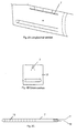
- a nozzle device 7 placed in the roof of the tunnel (figure 2A) is parallel to the longitudinal direction of the tunnel.
- the nozzle device is designed so that it spreads the gas over the belt or the cages in which the animals are located.
- the nozzle device 7 is shown in cross-section in figure 2B.
- the nozzle device can be arranged in the transverse direction of the tunnel.
- the nozzle device 7 itself, see figure 2C, is simply made from a pipe which is sealed at both ends. Holes 10 are drilled and arranged parallel to the longitudinal direction of the nozzle device and the gas can flow out of these holes.
- the nozzle device 7 is connected to a gas supply 11 for CO 2 and a gas supply 12 for O 2 , which are supplied via the regulation unit.
- the regulation unit for the control and supply of gas will be described later.
- Nozzle 13 for return/control gas (figure 2B) to the regulation unit is located in the centre of the section at the animals' head height so that gas can be sucked back for analysis.
- the analysis results control the addition of more gas.
- CO 2 and O 2 are added at the same time through the same nozzle device because there must be a given ratio between these gases at all times.
- the actual stunning begins and it is important to keep an accurate, uniform gas concentration throughout the zone. it is also important to have as little gas leakage as possible from zone 3 to zones 2 and 4.
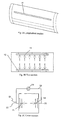
- a nozzle device 14, 15 (figures 3A, 3B, 3C) is placed on each of the side walls of the zone 3 in the longitudinal direction of the tunnel.
- the nozzle device 14, 15 are designed in the same way as in the first zone 2 and can be raised and lowered independently of one another so that the gas flow conditions can be changed (figure 3C).
- the nozzle device 14, 15 are connected to one another via a pipe system 18 (figure 3C) and a circulation pump 19 so that the gas can be circulated.
- the gas is sucked into one nozzle device 14 and blown out via the other nozzle device 15.
- the purpose of such circulation is to obtain more uniform gas distribution in the zone 3.
- the circulation will also contribute to less leakage of gas to the other, adjacent zones 2 and 4. It should be understood however, as an alternative arrangement (not shown), the gas circulation can be forced in the longitudinal or in the vertical direction of the tunnel zones by appropriate means.
- the outlet 20 for the return/control gas to the regulation unit is located in the circulation system on the suction side right opposite the nozzle device (figure 3C).
- This control gas constitutes a very small quantity of the circulation gas and is sucked into the regulation unit (to be mentioned later) for analysis, the results of which control the addition of gas to the system.
- Supply pipes 21, 22 for CO 2 and O 2 are connected to the circulation system on the blowing side just before the nozzle device 15 (figure 3C).
- the addition of gas is controlled by the regulation unit, which will be described later.
- CO 2 is added as a function of the CO 2 concentration measured in the gas from the zone 3, while the O 2 is added as a function of the quantity of CO 2 which is added.
- O 2 can be added as a function of the O 2 concentration measured in the gas from the zone 3.
- the third zone 4 is shown in figure 1A. This zone can be equipped in the same way as the first zone 2, but with the difference that the nozzle device are adapted to the curvature of the tunnel 1 (not shown).
- the tunnel which is described in the applicant's previous application, has a belt conveyor 9 which conveys the animals either freely or in transport boxes 8.
- the tunnel can easily be modified with a simpler transport arrangement which involves the transport boxes 8 being pulled through the tunnel 1 on two fixed rails 5 (figure 1B).
- a single chain with dogs 6 pulls the box or cage along with it through the three zones of the tunnel.
- the tunnel can be equipped with a powerful extractor fan which starts automatically if someone opens inspection or washing doors (not shown). Moreover, this may be controlled by the regulation unit.
- the equipment comprises a shaft 22 in which a cage 8 containing animals to be treated is lowered.
- the gas is added to the shaft in three phases as follows:
- the shaft 22 is connected to three separate gas tanks 23, 23', 23", each of which contains a gas mixture equivalent to the gas prescribed for each of the three treatment phases.
- Gas is circulated between the tank 23 and the shaft for the prescribed time in order to perform phase 1 of the stunning.
- the circulation is created by a fan 24 sucking gas from the shaft and blowing it into the tank 23. Gas from the tank 23 is then pressed back to the shaft via the nozzle device 25.
- Gas is then circulated between the tank 23' and the shaft 22 according to the same principle.
- Each tank is equipped with valves 50, 50', 50" and 51, 51', 51" which can be opened/closed in accordance with the type of gas mixture which is to be conducted into the shaft.
- each container 23, 23', 23" is controlled via a regulation unit which will be described later.
- CO 2 and O 2 are added to each tank when the regulation unit indicates that there is a need for more gas.
- FIG. 4B Another alternative is to build a deep shaft 26, see figure 4B.
- the cage 8 can be lowered and kept at various vertical levels in accordance with a predefined pattern.
- the upper part of the shaft corresponds to phase 1, the central part to phase 2 and the lower part to phase 3.
- a nozzle device 27 is connected to an opposite nozzle device 28 in a circulation system with a pump 29.
- the gas supply 30, 30' for CO 2 and O 2 comes from the regulation unit, which will be described later, and is connected to the circulation's blowing side close to the nozzle device 28.
- the outlet 34 for the return/control gas is located in the suction side of the circulation.
- the central gas circulation unit 32 and lower gas circulation unit 33 work according to the same principle but the gas concentrations will correspond to phases 2 and 3 respectively in the stunning process.
- the stunning takes place by the cage 8 being lowered to the first gas circulation unit 31. After the described dwell time, the cage is lowered to the second gas circulation unit 32 and finally to the bottom, the third gas circulation unit 33. Finally, the cage is quickly lifted out and the shaft is ready for the treatment of a new cage.
- the regulation unit is designed to modify the stunning atmosphere on the basis of desired parameters.
- CO 2 is the active gas in the process and its addition is controlled by the measured concentration in each individual zone.
- O 2 is a secondary gas and it is necessary to strive to maintain a normal level for this gas component.
- the need to add O 2 depends on the quantity of CO 2 added and can thus be controlled volumetrically on the basis of this quantity.
- O 2 is controlled by the measured concentration in each individual zone, and can be added automatically.
- the regulation equipment is contained in a cabinet 34.
- the cabinet is located as close to the zones as possible in order to limit the distance over which the return/control gas is conveyed.
- the cabinet 34 consists of the following parts which have the following functions:
- the meters are each connected to their stunning zone via a hose 36, 36', 36" and they are equipped with a pump 37, 37', 37" which sucks gas from the section into the measuring unit.
- the gas may, for example, be sucked from outlet 13 in figure 2B, outlet 20 in figure 3C or outlet 34 in figure 4B.
- CO 2 flows through the meters 35, 35', 35" continuously and is continuously analysed for each zone.
- the analysis results are transferred directly to a regulator 38, 38', 38".
- Each meter 35, 35', 35" with a regulator 38, 38', 38" controls its own phase in the stunning process.
- each regulator 38, 38', 38" is located in the cabinet and each is connected on one side to its own CO 2 meter.
- each regulator 38, 38', 38" is connected to its own set of (2) solenoid valves 39, 139, 39', 139', 39", 139".
- Each regulator can be set to the desired level of CO 2 concentration. If the CO 2 concentration indicated by the meter 35 is lower than the set level, a signal is sent to the solenoid valves 39, 139 that they are to open. If the concentration of CO 2 is higher than or equal to the set level, the solenoid valves are kept closed.
- Each set of solenoid valves 39, 139 (2) controls the supply of CO 2 and O 2 to its own zone.
- CO 2 is supplied via a pressure regulator 40 to the solenoid valve 39 and is conducted from the solenoid valve via a pipe 41 to the stunning zone, for example to inlet 11 in figure 2C, inlet 21 in figure 3C or inlet 30 in figure 4B.
- O 2 is supplied via a volume regulator 42 to the solenoid valve 139 and is conducted from the solenoid valve to the stunning zone via a pipe 43 which can be connected to inlet 12 in figure 2C, inlet 22 in figure 3C or inlet 30' in figure 4B.
- both CO 2 and O 2 are supplied.
- the quantity of O 2 can be regulated according to the desired mixture ratio in relation to CO 2 . This can be done by changing the O 2 supply via the volume regulator.
- the regulation cabinet 34 must also have room for supplementary and safety equipment 44 which may comprise:
- control system for supplying this gas component will be similar to that of CO 2 in the above described embodiment, comprising O 2 meters connected with corresponding regulators controlling the solenoid valves (not shown).
- the gas analysing and mixing system can be run automatically to ensure that the desired concentrations of both gases are kept within certain limits by means of a computerbased system analysing and controlling the gas addition.
Landscapes
- Life Sciences & Earth Sciences (AREA)
- Engineering & Computer Science (AREA)
- Food Science & Technology (AREA)
- Accessories For Mixers (AREA)
- Carbon And Carbon Compounds (AREA)
- Telephone Function (AREA)
- Sampling And Sample Adjustment (AREA)
- Air Bags (AREA)
- Food Preservation Except Freezing, Refrigeration, And Drying (AREA)
- Accommodation For Nursing Or Treatment Tables (AREA)
- Treating Waste Gases (AREA)
- Transition And Organic Metals Composition Catalysts For Addition Polymerization (AREA)
Abstract
Description
| 18-20% | CO2 |
| 18-22% | O2 |
| 58-64% | Air |
| 33-35% | CO2 |
| 18-22% | O2 |
| 43-49% | Air |
| 54-60% | CO2 |
| 18-22% | O2 |
| 18-28% | Air |
- Figure 1A
- shows a stunning tunnel with three treatment zones,
- Figure 1B
- shows a cross-section of the tunnel and details of a transport system,
- Figure 2A
- shows a longitudinal section of details of the tunnel shown in figure 1A,
- Figure 2B
- shows a cross-section of the tunnel shown in figure 1A,
- Figure 2C
- shows details of a nozzle device,
- Figure 3A
- shows a longitudinal section of part of the tunnel shown in figure 1A,
- Figure 3B
- shows a top section of part of the tunnel shown in figure 1A,
- Figure 3C
- shows a cross-section of part of the tunnel shown in figure 1A,
- Figure 4A
- shows a section of a system for the creation of up to three different gas mixtures in one chamber, the system being no embodiment of the invention as claimed,
- Figure 4B
- shows a section of a shaft with means for the production of gas mixtures at different vertical levels,
- Figure 5
- shows a diagram of equipment with means of regulation for the production of one or more gas mixtures.
The
- Cut-out functions for emergency stop and door openers (washing/inspection doors).
- Start of emergency fans.
- Control of extractor fans for free gas.
- Emergency warnings of high CO2 content in the room.
Claims (7)
- A method for producing and maintaining a gas mixture in one or more zones for the stunning or killing of poultry, where the gas mixture includes carbon dioxide gas (CO2) and oxygen (O2) and some air,
characterised in that
the concentration of oxygen in the mixture is at a level equivalent to the concentration of oxygen in naturally occurring air or lower, and within the range 22%-10%, carbon dioxide gas is added as a function of the carbon dioxide concentration measured in the gas from the zone(s) by regulating-/supply equipment (35, 38, 39, 40), and oxygen is added as a function of the quantity of carbon dioxide added or added as a function of oxygen concentration measured in the gas from the zone(s). - A method in accordance with claim 1,
characterised in that
the gas mixture is added at one side of the zone and the gas is sucked out through the other side of the zone, thus causing the gas mixture to flow through the zone or along the zone. - A method in accordance with claim 1,
characterised in that
the carbon dioxide concentration is determined on the basis of the gas which is sucked out of the chamber through an outlet (13, 20, 34). - Equipment for producing and maintaining a gas mixture in one or more zones for the stunning or killing of poultry, where the gas mixture includes carbon dioxide gas (CO2) and oxygen (O2) and some air,
characterised in that the carbon dioxide concentration is measured in gas from the zone(s) by a meter (35) which gives a signal to a regulator (38) which opens and closes a valve (39) for the supply of carbon dioxide gas from a store (40) to the zone and a valve (139) for the supply of oxygen from a store (42) to the zone, and that the regulator is designed in such a way that oxygen is added as a function of the quantity of carbon dioxide added to the zone or added as a function of the oxygen concentration measured in the gas from the zone(s), where the concentration of oxygen in the gas mixture is at a level equivalent to the concentration of oxygen in naturally occurring air or lower, and within the range 22% -10%, - Equipment in accordance with claim 4,
characterised in that
the gas is added so that it flows through the zone by means of nozzle devices (14, 15) fitted to two opposite sides of the zone. - Equipment in accordance with claim 4,
characterised in that
it is used in connection with a stunning tunnel (1), preferably comprising three zones. - Equipment in accordance with claim 4,
characterised in that
it is used in connection with a stunning shaft (26) comprising three treatment zones arranged at different vertical levels.
Applications Claiming Priority (3)
| Application Number | Priority Date | Filing Date | Title |
|---|---|---|---|
| NO982402 | 1998-05-27 | ||
| NO19982402A NO308402B1 (en) | 1998-05-27 | 1998-05-27 | Process and equipment for forming and maintaining a gas mixture |
| PCT/NO1999/000150 WO1999060861A1 (en) | 1998-05-27 | 1999-05-10 | A method and equipment for the production of a gas mixture |
Publications (2)
| Publication Number | Publication Date |
|---|---|
| EP1079693A1 EP1079693A1 (en) | 2001-03-07 |
| EP1079693B1 true EP1079693B1 (en) | 2002-03-06 |
Family
ID=19902080
Family Applications (1)
| Application Number | Title | Priority Date | Filing Date |
|---|---|---|---|
| EP99921299A Expired - Lifetime EP1079693B1 (en) | 1998-05-27 | 1999-05-10 | A method and equipment for the production of a gas mixture |
Country Status (15)
| Country | Link |
|---|---|
| US (1) | US6623347B1 (en) |
| EP (1) | EP1079693B1 (en) |
| AT (1) | ATE213909T1 (en) |
| AU (1) | AU3854599A (en) |
| BR (1) | BR9910735A (en) |
| CA (1) | CA2333354C (en) |
| DE (1) | DE69900989T2 (en) |
| DK (1) | DK1079693T3 (en) |
| ES (1) | ES2175971T3 (en) |
| ID (1) | ID26905A (en) |
| MY (1) | MY121821A (en) |
| NO (1) | NO308402B1 (en) |
| PL (1) | PL190881B1 (en) |
| PT (1) | PT1079693E (en) |
| WO (1) | WO1999060861A1 (en) |
Families Citing this family (13)
| Publication number | Priority date | Publication date | Assignee | Title |
|---|---|---|---|---|
| EP1587372B1 (en) * | 2003-01-22 | 2008-03-19 | Linco Food Systems A/S | Method and system for gas stunning of poultry for slaughter |
| US8597089B2 (en) * | 2005-07-08 | 2013-12-03 | Praxair Technology, Inc. | System and method for treating live cargo such as poultry with gas |
| US20070026779A1 (en) * | 2005-07-08 | 2007-02-01 | Lang Gary D | Poultry stunning |
| US7794310B2 (en) | 2005-07-08 | 2010-09-14 | Praxair Technology, Inc. | Stunning animals such as poultry with gas |
| US8272926B2 (en) * | 2006-08-23 | 2012-09-25 | Praxair Technology, Inc. | System and method for stunning poultry with gas |
| US8323080B2 (en) * | 2007-04-11 | 2012-12-04 | Praxair Technology, Inc. | System and method for stunning poultry with gas |
| EP2674032B1 (en) * | 2012-06-14 | 2017-05-03 | Linde Aktiengesellschaft | Carbon dioxide based method and system for the humane mass culling of poultry and sterilisation of rearing sheds |
| US9192170B2 (en) * | 2013-08-19 | 2015-11-24 | Naturally Recycled Proteins | Systems and methods for conveying, anesthetizing, and killing poultry |
| US9402403B2 (en) * | 2014-12-10 | 2016-08-02 | Massimo Zanotti | Method and apparatus for stunning animals intended to be slaughtered |
| WO2018211231A1 (en) * | 2017-05-16 | 2018-11-22 | Gallus Solutions Ltd | System and method for stunning animals |
| DE102021112741A1 (en) * | 2021-05-17 | 2022-11-17 | Air Liquide Deutschland Gmbh | Modular system for applying stunning gas to stun animals before slaughter |
| EP4447687A1 (en) | 2021-12-16 | 2024-10-23 | BAADER Food Systems Denmark A/S | Apparatus and method for stunning poultry in a stunning chamber above ground |
| WO2025098684A1 (en) | 2023-11-07 | 2025-05-15 | Marel Meat A/S | Method and apparatus for anesthetizing slaughter animals |
Family Cites Families (6)
| Publication number | Priority date | Publication date | Assignee | Title |
|---|---|---|---|---|
| GB1521700A (en) * | 1975-12-11 | 1978-08-16 | Universities Federation For An | Euthanasia of animals |
| GB8928934D0 (en) * | 1989-12-21 | 1990-02-28 | Boc Group Plc | Treatment of birds |
| GB8928935D0 (en) | 1989-12-21 | 1990-02-28 | Boc Group Plc | Treatment of poultry |
| NL9300254A (en) * | 1992-12-30 | 1994-07-18 | Stork Pmt | Method and device for stunning stunning animals. |
| US5435776A (en) | 1994-07-21 | 1995-07-25 | Liquid Carbonic Corporation | Poultry stunning with carbon dioxide |
| NO970229D0 (en) * | 1997-01-17 | 1997-01-17 | Norsk Hydro As | Method and equipment for the treatment of poultry for slaughter |
-
1998
- 1998-05-27 NO NO19982402A patent/NO308402B1/en not_active IP Right Cessation
-
1999
- 1999-05-10 PL PL344522A patent/PL190881B1/en unknown
- 1999-05-10 AT AT99921299T patent/ATE213909T1/en active
- 1999-05-10 DE DE69900989T patent/DE69900989T2/en not_active Expired - Lifetime
- 1999-05-10 DK DK99921299T patent/DK1079693T3/en active
- 1999-05-10 EP EP99921299A patent/EP1079693B1/en not_active Expired - Lifetime
- 1999-05-10 PT PT99921299T patent/PT1079693E/en unknown
- 1999-05-10 WO PCT/NO1999/000150 patent/WO1999060861A1/en not_active Ceased
- 1999-05-10 AU AU38545/99A patent/AU3854599A/en not_active Abandoned
- 1999-05-10 ID IDW20002446A patent/ID26905A/en unknown
- 1999-05-10 US US09/701,207 patent/US6623347B1/en not_active Expired - Lifetime
- 1999-05-10 ES ES99921299T patent/ES2175971T3/en not_active Expired - Lifetime
- 1999-05-10 BR BR9910735-0A patent/BR9910735A/en not_active IP Right Cessation
- 1999-05-10 CA CA002333354A patent/CA2333354C/en not_active Expired - Lifetime
- 1999-05-15 MY MYPI99001923A patent/MY121821A/en unknown
Also Published As
| Publication number | Publication date |
|---|---|
| AU3854599A (en) | 1999-12-13 |
| ATE213909T1 (en) | 2002-03-15 |
| PT1079693E (en) | 2002-08-30 |
| EP1079693A1 (en) | 2001-03-07 |
| CA2333354C (en) | 2007-04-10 |
| DE69900989D1 (en) | 2002-04-11 |
| DE69900989T2 (en) | 2002-10-17 |
| WO1999060861A1 (en) | 1999-12-02 |
| BR9910735A (en) | 2001-02-13 |
| CA2333354A1 (en) | 1999-12-02 |
| DK1079693T3 (en) | 2002-06-24 |
| US6623347B1 (en) | 2003-09-23 |
| NO308402B1 (en) | 2000-09-11 |
| ID26905A (en) | 2001-02-15 |
| MY121821A (en) | 2006-02-28 |
| NO982402L (en) | 1999-11-29 |
| ES2175971T3 (en) | 2002-11-16 |
| PL190881B1 (en) | 2006-02-28 |
| NO982402D0 (en) | 1998-05-27 |
| PL344522A1 (en) | 2001-11-05 |
Similar Documents
| Publication | Publication Date | Title |
|---|---|---|
| CA2278469C (en) | A procedure and equipment for treating poultry before slaughter | |
| US6623347B1 (en) | Method and equipment for the production of a gas mixture | |
| CA2275714C (en) | Improved method and apparatus for anaesthetizing animals for slaughter with gas | |
| JP3414401B2 (en) | Equipment for stunning poultry | |
| CA1069433A (en) | Animal euthanasia | |
| US10757948B2 (en) | Pre-stunning or stunning of animals with a combination of O2, CO2 and NO2 | |
| US6063295A (en) | Apparatus and method to increase oxygen levels in livestock drinking water | |
| KR102608869B1 (en) | How to perform a procedure on an animal that involves stunning and/or slaughtering the animal | |
| WO2001037673A1 (en) | Method and apparatus for unloading poultry | |
| MXPA00011608A (en) | A method and equipment for the production of a gas mixture | |
| CA3217599A1 (en) | Modular system and method for delivering anaesthetic gas for stunning animals prior to slaughter | |
| CN113397752A (en) | Animal experiment device and method for mixed gas nerve protective agent | |
| CN119136676A (en) | Method and apparatus for anesthetizing animals for slaughter | |
| CN118401114A (en) | Apparatus and method for stunning poultry in a stunning chamber above ground | |
| GB2362083A (en) | Apparatus for the euthanasia of young poultry | |
| US20240423223A1 (en) | Stunning system and method for stunning an animal to be slaughtered in an animal-friendly and inexpensive manner | |
| WO2018211231A1 (en) | System and method for stunning animals | |
| AU2024378584A1 (en) | Method and apparatus for anesthetizing slaughter animals | |
| WO2025098684A1 (en) | Method and apparatus for anesthetizing slaughter animals | |
| GB2564725A (en) | System and method for stunning animals | |
| NO327948B1 (en) | Method and equipment for the treatment of poultry for slaughter | |
| JPH0335750A (en) | Anesthetic treating of edible fowl |
Legal Events
| Date | Code | Title | Description |
|---|---|---|---|
| PUAI | Public reference made under article 153(3) epc to a published international application that has entered the european phase |
Free format text: ORIGINAL CODE: 0009012 |
|
| 17P | Request for examination filed |
Effective date: 20001227 |
|
| AK | Designated contracting states |
Kind code of ref document: A1 Designated state(s): AT BE CH CY DE DK ES FI FR GB GR IE IT LI LU MC NL PT SE |
|
| GRAG | Despatch of communication of intention to grant |
Free format text: ORIGINAL CODE: EPIDOS AGRA |
|
| 17Q | First examination report despatched |
Effective date: 20010426 |
|
| GRAG | Despatch of communication of intention to grant |
Free format text: ORIGINAL CODE: EPIDOS AGRA |
|
| GRAH | Despatch of communication of intention to grant a patent |
Free format text: ORIGINAL CODE: EPIDOS IGRA |
|
| GRAH | Despatch of communication of intention to grant a patent |
Free format text: ORIGINAL CODE: EPIDOS IGRA |
|
| REG | Reference to a national code |
Ref country code: GB Ref legal event code: IF02 |
|
| GRAA | (expected) grant |
Free format text: ORIGINAL CODE: 0009210 |
|
| AK | Designated contracting states |
Kind code of ref document: B1 Designated state(s): AT BE CH CY DE DK ES FI FR GB GR IE IT LI LU MC NL PT SE |
|
| REF | Corresponds to: |
Ref document number: 213909 Country of ref document: AT Date of ref document: 20020315 Kind code of ref document: T |
|
| REG | Reference to a national code |
Ref country code: CH Ref legal event code: EP |
|
| REF | Corresponds to: |
Ref document number: 69900989 Country of ref document: DE Date of ref document: 20020411 |
|
| REG | Reference to a national code |
Ref country code: CH Ref legal event code: NV Representative=s name: E. BLUM & CO. PATENTANWAELTE |
|
| REG | Reference to a national code |
Ref country code: DK Ref legal event code: T3 |
|
| ET | Fr: translation filed | ||
| REG | Reference to a national code |
Ref country code: PT Ref legal event code: SC4A Free format text: AVAILABILITY OF NATIONAL TRANSLATION Effective date: 20020515 |
|
| REG | Reference to a national code |
Ref country code: GR Ref legal event code: EP Ref document number: 20020401523 Country of ref document: GR |
|
| REG | Reference to a national code |
Ref country code: ES Ref legal event code: FG2A Ref document number: 2175971 Country of ref document: ES Kind code of ref document: T3 |
|
| PLBE | No opposition filed within time limit |
Free format text: ORIGINAL CODE: 0009261 |
|
| STAA | Information on the status of an ep patent application or granted ep patent |
Free format text: STATUS: NO OPPOSITION FILED WITHIN TIME LIMIT |
|
| 26N | No opposition filed |
Effective date: 20021209 |
|
| REG | Reference to a national code |
Ref country code: CH Ref legal event code: PUE Owner name: YARA INTERNATIONAL ASA Free format text: NORSK HYDRO ASA#BYGDOY ALLE 2#0240 OSLO (NO) -TRANSFER TO- YARA INTERNATIONAL ASA#BYGDOY ALLE 2, P.O. BOX 2464 SOLLI#0202 OSLO (NO) |
|
| REG | Reference to a national code |
Ref country code: PT Ref legal event code: PC4A Free format text: YARA INTERNATIONAL ASA NO Effective date: 20041008 |
|
| NLS | Nl: assignments of ep-patents |
Owner name: YARA INTERNATIONAL ASA |
|
| REG | Reference to a national code |
Ref country code: GB Ref legal event code: 732E |
|
| REG | Reference to a national code |
Ref country code: FR Ref legal event code: TP |
|
| REG | Reference to a national code |
Ref country code: CH Ref legal event code: PFA Owner name: YARA INTERNATIONAL ASA Free format text: YARA INTERNATIONAL ASA#BYGDOY ALLE 2, P.O. BOX 2464 SOLLI#0202 OSLO (NO) -TRANSFER TO- YARA INTERNATIONAL ASA#BYGDOY ALLE 2, P.O. BOX 2464 SOLLI#0202 OSLO (NO) |
|
| PGFP | Annual fee paid to national office [announced via postgrant information from national office to epo] |
Ref country code: LU Payment date: 20110603 Year of fee payment: 13 |
|
| PGFP | Annual fee paid to national office [announced via postgrant information from national office to epo] |
Ref country code: MC Payment date: 20120511 Year of fee payment: 14 |
|
| PG25 | Lapsed in a contracting state [announced via postgrant information from national office to epo] |
Ref country code: MC Free format text: LAPSE BECAUSE OF NON-PAYMENT OF DUE FEES Effective date: 20130531 |
|
| REG | Reference to a national code |
Ref country code: DE Ref legal event code: R082 Ref document number: 69900989 Country of ref document: DE Representative=s name: DR. RALF KOTITSCHKE, DE Ref country code: DE Ref legal event code: R082 Ref document number: 69900989 Country of ref document: DE Representative=s name: KOTITSCHKE & HEURUNG PARTNERSCHAFT MBB PATENT-, DE |
|
| PG25 | Lapsed in a contracting state [announced via postgrant information from national office to epo] |
Ref country code: LU Free format text: LAPSE BECAUSE OF NON-PAYMENT OF DUE FEES Effective date: 20130510 |
|
| REG | Reference to a national code |
Ref country code: FR Ref legal event code: PLFP Year of fee payment: 18 |
|
| REG | Reference to a national code |
Ref country code: FR Ref legal event code: PLFP Year of fee payment: 19 |
|
| REG | Reference to a national code |
Ref country code: FR Ref legal event code: PLFP Year of fee payment: 20 |
|
| PGFP | Annual fee paid to national office [announced via postgrant information from national office to epo] |
Ref country code: PT Payment date: 20180419 Year of fee payment: 20 Ref country code: IE Payment date: 20180529 Year of fee payment: 20 Ref country code: DK Payment date: 20180525 Year of fee payment: 20 Ref country code: DE Payment date: 20180529 Year of fee payment: 20 Ref country code: FI Payment date: 20180529 Year of fee payment: 20 Ref country code: ES Payment date: 20180601 Year of fee payment: 20 Ref country code: CH Payment date: 20180601 Year of fee payment: 20 |
|
| PGFP | Annual fee paid to national office [announced via postgrant information from national office to epo] |
Ref country code: NL Payment date: 20180526 Year of fee payment: 20 Ref country code: FR Payment date: 20180525 Year of fee payment: 20 Ref country code: BE Payment date: 20180528 Year of fee payment: 20 Ref country code: IT Payment date: 20180522 Year of fee payment: 20 Ref country code: AT Payment date: 20180419 Year of fee payment: 20 Ref country code: GR Payment date: 20180529 Year of fee payment: 20 |
|
| PGFP | Annual fee paid to national office [announced via postgrant information from national office to epo] |
Ref country code: SE Payment date: 20180529 Year of fee payment: 20 |
|
| PGFP | Annual fee paid to national office [announced via postgrant information from national office to epo] |
Ref country code: GB Payment date: 20180529 Year of fee payment: 20 Ref country code: CY Payment date: 20180423 Year of fee payment: 20 |
|
| REG | Reference to a national code |
Ref country code: DE Ref legal event code: R071 Ref document number: 69900989 Country of ref document: DE |
|
| REG | Reference to a national code |
Ref country code: DK Ref legal event code: EUP Effective date: 20190510 |
|
| REG | Reference to a national code |
Ref country code: CH Ref legal event code: PL Ref country code: NL Ref legal event code: MK Effective date: 20190509 |
|
| REG | Reference to a national code |
Ref country code: GB Ref legal event code: PE20 Expiry date: 20190509 |
|
| REG | Reference to a national code |
Ref country code: BE Ref legal event code: MK Effective date: 20190510 |
|
| REG | Reference to a national code |
Ref country code: AT Ref legal event code: MK07 Ref document number: 213909 Country of ref document: AT Kind code of ref document: T Effective date: 20190510 |
|
| REG | Reference to a national code |
Ref country code: IE Ref legal event code: MK9A |
|
| REG | Reference to a national code |
Ref country code: SE Ref legal event code: EUG |
|
| PG25 | Lapsed in a contracting state [announced via postgrant information from national office to epo] |
Ref country code: PT Free format text: LAPSE BECAUSE OF EXPIRATION OF PROTECTION Effective date: 20190516 Ref country code: IE Free format text: LAPSE BECAUSE OF EXPIRATION OF PROTECTION Effective date: 20190510 |
|
| PG25 | Lapsed in a contracting state [announced via postgrant information from national office to epo] |
Ref country code: GB Free format text: LAPSE BECAUSE OF EXPIRATION OF PROTECTION Effective date: 20190509 |
|
| REG | Reference to a national code |
Ref country code: ES Ref legal event code: FD2A Effective date: 20200804 |
|
| PG25 | Lapsed in a contracting state [announced via postgrant information from national office to epo] |
Ref country code: ES Free format text: LAPSE BECAUSE OF EXPIRATION OF PROTECTION Effective date: 20190511 |