EP1079494A2 - Battery control apparatus for hybrid vehicle - Google Patents
Battery control apparatus for hybrid vehicle Download PDFInfo
- Publication number
- EP1079494A2 EP1079494A2 EP00118530A EP00118530A EP1079494A2 EP 1079494 A2 EP1079494 A2 EP 1079494A2 EP 00118530 A EP00118530 A EP 00118530A EP 00118530 A EP00118530 A EP 00118530A EP 1079494 A2 EP1079494 A2 EP 1079494A2
- Authority
- EP
- European Patent Office
- Prior art keywords
- battery
- charge
- residual
- temperature
- battery charge
- Prior art date
- Legal status (The legal status is an assumption and is not a legal conclusion. Google has not performed a legal analysis and makes no representation as to the accuracy of the status listed.)
- Granted
Links
Images



Classifications
-
- B—PERFORMING OPERATIONS; TRANSPORTING
- B60—VEHICLES IN GENERAL
- B60W—CONJOINT CONTROL OF VEHICLE SUB-UNITS OF DIFFERENT TYPE OR DIFFERENT FUNCTION; CONTROL SYSTEMS SPECIALLY ADAPTED FOR HYBRID VEHICLES; ROAD VEHICLE DRIVE CONTROL SYSTEMS FOR PURPOSES NOT RELATED TO THE CONTROL OF A PARTICULAR SUB-UNIT
- B60W10/00—Conjoint control of vehicle sub-units of different type or different function
- B60W10/24—Conjoint control of vehicle sub-units of different type or different function including control of energy storage means
- B60W10/26—Conjoint control of vehicle sub-units of different type or different function including control of energy storage means for electrical energy, e.g. batteries or capacitors
-
- B—PERFORMING OPERATIONS; TRANSPORTING
- B60—VEHICLES IN GENERAL
- B60K—ARRANGEMENT OR MOUNTING OF PROPULSION UNITS OR OF TRANSMISSIONS IN VEHICLES; ARRANGEMENT OR MOUNTING OF PLURAL DIVERSE PRIME-MOVERS IN VEHICLES; AUXILIARY DRIVES FOR VEHICLES; INSTRUMENTATION OR DASHBOARDS FOR VEHICLES; ARRANGEMENTS IN CONNECTION WITH COOLING, AIR INTAKE, GAS EXHAUST OR FUEL SUPPLY OF PROPULSION UNITS IN VEHICLES
- B60K6/00—Arrangement or mounting of plural diverse prime-movers for mutual or common propulsion, e.g. hybrid propulsion systems comprising electric motors and internal combustion engines
- B60K6/20—Arrangement or mounting of plural diverse prime-movers for mutual or common propulsion, e.g. hybrid propulsion systems comprising electric motors and internal combustion engines the prime-movers consisting of electric motors and internal combustion engines, e.g. HEVs
- B60K6/42—Arrangement or mounting of plural diverse prime-movers for mutual or common propulsion, e.g. hybrid propulsion systems comprising electric motors and internal combustion engines the prime-movers consisting of electric motors and internal combustion engines, e.g. HEVs characterised by the architecture of the hybrid electric vehicle
- B60K6/48—Parallel type
- B60K6/485—Motor-assist type
-
- B—PERFORMING OPERATIONS; TRANSPORTING
- B60—VEHICLES IN GENERAL
- B60K—ARRANGEMENT OR MOUNTING OF PROPULSION UNITS OR OF TRANSMISSIONS IN VEHICLES; ARRANGEMENT OR MOUNTING OF PLURAL DIVERSE PRIME-MOVERS IN VEHICLES; AUXILIARY DRIVES FOR VEHICLES; INSTRUMENTATION OR DASHBOARDS FOR VEHICLES; ARRANGEMENTS IN CONNECTION WITH COOLING, AIR INTAKE, GAS EXHAUST OR FUEL SUPPLY OF PROPULSION UNITS IN VEHICLES
- B60K6/00—Arrangement or mounting of plural diverse prime-movers for mutual or common propulsion, e.g. hybrid propulsion systems comprising electric motors and internal combustion engines
- B60K6/20—Arrangement or mounting of plural diverse prime-movers for mutual or common propulsion, e.g. hybrid propulsion systems comprising electric motors and internal combustion engines the prime-movers consisting of electric motors and internal combustion engines, e.g. HEVs
- B60K6/50—Architecture of the driveline characterised by arrangement or kind of transmission units
- B60K6/54—Transmission for changing ratio
-
- B—PERFORMING OPERATIONS; TRANSPORTING
- B60—VEHICLES IN GENERAL
- B60L—PROPULSION OF ELECTRICALLY-PROPELLED VEHICLES; SUPPLYING ELECTRIC POWER FOR AUXILIARY EQUIPMENT OF ELECTRICALLY-PROPELLED VEHICLES; ELECTRODYNAMIC BRAKE SYSTEMS FOR VEHICLES IN GENERAL; MAGNETIC SUSPENSION OR LEVITATION FOR VEHICLES; MONITORING OPERATING VARIABLES OF ELECTRICALLY-PROPELLED VEHICLES; ELECTRIC SAFETY DEVICES FOR ELECTRICALLY-PROPELLED VEHICLES
- B60L58/00—Methods or circuit arrangements for monitoring or controlling batteries or fuel cells, specially adapted for electric vehicles
- B60L58/10—Methods or circuit arrangements for monitoring or controlling batteries or fuel cells, specially adapted for electric vehicles for monitoring or controlling batteries
-
- H—ELECTRICITY
- H02—GENERATION; CONVERSION OR DISTRIBUTION OF ELECTRIC POWER
- H02J—ELECTRIC POWER NETWORKS; CIRCUIT ARRANGEMENTS OR SYSTEMS FOR SUPPLYING OR DISTRIBUTING ELECTRIC POWER; SYSTEMS FOR STORING ELECTRIC ENERGY
- H02J7/00—Circuit arrangements for charging or discharging batteries or for supplying loads from batteries
- H02J7/14—Circuit arrangements for charging or discharging batteries or for supplying loads from batteries for charging batteries from dynamo-electric generators driven at varying speed, e.g. on vehicle
- H02J7/1415—Circuit arrangements for charging or discharging batteries or for supplying loads from batteries for charging batteries from dynamo-electric generators driven at varying speed, e.g. on vehicle with a generator driven by a prime mover other than the motor of a vehicle
-
- H—ELECTRICITY
- H02—GENERATION; CONVERSION OR DISTRIBUTION OF ELECTRIC POWER
- H02J—ELECTRIC POWER NETWORKS; CIRCUIT ARRANGEMENTS OR SYSTEMS FOR SUPPLYING OR DISTRIBUTING ELECTRIC POWER; SYSTEMS FOR STORING ELECTRIC ENERGY
- H02J7/00—Circuit arrangements for charging or discharging batteries or for supplying loads from batteries
- H02J7/90—Regulation of charging or discharging current or voltage
- H02J7/971—Regulation of charging or discharging current or voltage the charge cycle being controlled or terminated in response to non-electric parameters
- H02J7/975—Regulation of charging or discharging current or voltage the charge cycle being controlled or terminated in response to non-electric parameters in response to temperature
- H02J7/977—Regulation of charging or discharging current or voltage the charge cycle being controlled or terminated in response to non-electric parameters in response to temperature of the battery
-
- Y—GENERAL TAGGING OF NEW TECHNOLOGICAL DEVELOPMENTS; GENERAL TAGGING OF CROSS-SECTIONAL TECHNOLOGIES SPANNING OVER SEVERAL SECTIONS OF THE IPC; TECHNICAL SUBJECTS COVERED BY FORMER USPC CROSS-REFERENCE ART COLLECTIONS [XRACs] AND DIGESTS
- Y02—TECHNOLOGIES OR APPLICATIONS FOR MITIGATION OR ADAPTATION AGAINST CLIMATE CHANGE
- Y02T—CLIMATE CHANGE MITIGATION TECHNOLOGIES RELATED TO TRANSPORTATION
- Y02T10/00—Road transport of goods or passengers
- Y02T10/60—Other road transportation technologies with climate change mitigation effect
- Y02T10/62—Hybrid vehicles
-
- Y—GENERAL TAGGING OF NEW TECHNOLOGICAL DEVELOPMENTS; GENERAL TAGGING OF CROSS-SECTIONAL TECHNOLOGIES SPANNING OVER SEVERAL SECTIONS OF THE IPC; TECHNICAL SUBJECTS COVERED BY FORMER USPC CROSS-REFERENCE ART COLLECTIONS [XRACs] AND DIGESTS
- Y02—TECHNOLOGIES OR APPLICATIONS FOR MITIGATION OR ADAPTATION AGAINST CLIMATE CHANGE
- Y02T—CLIMATE CHANGE MITIGATION TECHNOLOGIES RELATED TO TRANSPORTATION
- Y02T10/00—Road transport of goods or passengers
- Y02T10/60—Other road transportation technologies with climate change mitigation effect
- Y02T10/70—Energy storage systems for electromobility, e.g. batteries
-
- Y—GENERAL TAGGING OF NEW TECHNOLOGICAL DEVELOPMENTS; GENERAL TAGGING OF CROSS-SECTIONAL TECHNOLOGIES SPANNING OVER SEVERAL SECTIONS OF THE IPC; TECHNICAL SUBJECTS COVERED BY FORMER USPC CROSS-REFERENCE ART COLLECTIONS [XRACs] AND DIGESTS
- Y10—TECHNICAL SUBJECTS COVERED BY FORMER USPC
- Y10S—TECHNICAL SUBJECTS COVERED BY FORMER USPC CROSS-REFERENCE ART COLLECTIONS [XRACs] AND DIGESTS
- Y10S903/00—Hybrid electric vehicles, HEVS
- Y10S903/902—Prime movers comprising electrical and internal combustion motors
- Y10S903/903—Prime movers comprising electrical and internal combustion motors having energy storing means, e.g. battery, capacitor
-
- Y—GENERAL TAGGING OF NEW TECHNOLOGICAL DEVELOPMENTS; GENERAL TAGGING OF CROSS-SECTIONAL TECHNOLOGIES SPANNING OVER SEVERAL SECTIONS OF THE IPC; TECHNICAL SUBJECTS COVERED BY FORMER USPC CROSS-REFERENCE ART COLLECTIONS [XRACs] AND DIGESTS
- Y10—TECHNICAL SUBJECTS COVERED BY FORMER USPC
- Y10S—TECHNICAL SUBJECTS COVERED BY FORMER USPC CROSS-REFERENCE ART COLLECTIONS [XRACs] AND DIGESTS
- Y10S903/00—Hybrid electric vehicles, HEVS
- Y10S903/902—Prime movers comprising electrical and internal combustion motors
- Y10S903/903—Prime movers comprising electrical and internal combustion motors having energy storing means, e.g. battery, capacitor
- Y10S903/904—Component specially adapted for hev
- Y10S903/915—Specific drive or transmission adapted for hev
- Y10S903/917—Specific drive or transmission adapted for hev with transmission for changing gear ratio
Definitions
- the present invention relates to a battery control apparatus for controlling the battery installed in a hybrid vehicle, and relates in particular to a battery control apparatus to control charging or discharging amount according to the temperature of the battery.
- Hybrid vehicles that carry a separate motor in addition to a drive engine as a power source are known.
- Hybrid vehicles are divided into a series-hybrid type and a parallel-hybrid type.
- the series-hybrid type vehicles in which the engine drives a generator that outputs electric power to operate the motor to drive the wheels.
- the engine and the wheels are not linked, the engine can be operated at roughly a constant speed in a range of rotational speed to produce high fuel cost but low emission, so that better fuel cost and lower emission can be achieved compared with the conventional engine-driven vehicles.
- the parallel-hybrid vehicles in which a motor linked mechanically to the drive engine is used to assist the rotation of the drive shaft of the engine as well as to charge a storage battery using the same motor as a generator to store electrical charges in the battery, and the generated electricity is used also for electrical devices in the vehicle.
- the motor is connected directly to the output shaft of the engine, and the motor functions as the generator to charge the battery during deceleration of the vehicle, and another type in which either or both the engine and the motor are able to generate drive power, and a generator is provided separately.
- the demand of the driver can be met by having the motor assisting the output of the engine during the acceleration stage, or by having the motor charging the battery during the deceleration stage of the vehicle, due to "deceleration regeneration", for example, so that the electrical energy of the battery (referred to as the residual battery charge, hereinafter) can be maintained.
- the battery used for hybrid vehicles exhibit a property that charging efficiency is rapidly lowered beyond a certain temperature. This temperature is dependent on the characteristics of the battery. If charging is continued when the battery is at a temperature higher than such a temperature, the charging energy is converted to heat and cannot be stored in the battery as electrical energy.
- the capacity of each module can vary if the temperatures of the modules are not uniform. Variations in the module temperature can occur particularly easily when the battery temperature increases due to the effects of surrounding temperatures. Furthermore, when the battery temperature is high, it becomes difficult to detect the high-limit of residual battery charge, because of decrease in changes in the battery voltage required to detect the residual charge upper limit. For this reason, batteries in hybrid vehicles are often provided with a cooling facility for cooling the batteries so as to maintain the battery temperature below a transition temperature that charging efficiency is rapidly lowered.
- the cooling facility can only function during the vehicle is motion, and therefore, when the vehicle is stationary, battery alone cannot be cooled. For this reason, the battery installed in the interior of the vehicle under the burning sun raises its temperature as the surrounding temperature rises. Under such a condition, even when the battery is cooled by moving the vehicle, it takes time to cool the battery temperature to less than the transition temperature. So long as the battery temperature remains high, charging does not produce storage of electrical energy in the battery so that it leads to a problem that the battery temperature can further increase.
- an object of the present invention to provide an apparatus to control charge/discharge process of the battery dependent upon the temperature of the battery so as to prevent degradation of the battery.
- the first aspect of the invention relates to an apparatus for controlling a battery installed in a hybrid vehicle having a combustion engine (engine 1 for example) for providing a driving force, an electric motor (motor 2 for example) for generating a drive-assist force for assisting the output of the engine, wherein the battery (battery 8 for example) supplies electrical power to the motor, and, when the drive-assist force is not required by the engine, the motor is used as a generator to charged the battery, the apparatus is comprised by: a residual battery charge computation device (residual battery charge computation device 91 for example) for computing a level of residual battery charge in the battery; a battery temperature measuring device (temperature sensor in the example) for measuring a temperature of the battery; and a charge/discharge controller (charge/discharge control section 92 for example) that operates in such a way that, when a battery temperature measured by the battery temperature measuring device exceeds a specific temperature (the threshold temperature at which the charging efficiency decreases noticeably, for example, and the battery 8 meets
- the apparatus is provided with a residual battery charge computation device for computing a level of residual battery charge in the battery; a battery temperature measuring device for measuring a temperature of the battery; and a charge/discharge controller that operates in such a way that, when a battery temperature measured by the battery temperature measuring device is a threshold temperature that begins lowering of charging efficiency, the charge/discharge controller does not permit charging but permits only discharging until the residual battery charge is lowered to the use-permitted low-limit, so that, when the battery temperature is high, charging is not permitted until the battery temperature decreases, thereby preventing further increase in the battery temperature and degradation of the battery that are caused by low charging efficiency.
- a second aspect of the invention relates to the apparatus, wherein, after the battery has reached the first specified value of residual battery charge (use-permitted low- limit of the residual charge, for example), the charge/discharge controller permits the battery to be charged to a level not exceeding a level defined by a second specific value (charge-permitted restriction value, for example) of the residual battery charge, which is higher than the first specified value of the residual battery charge (as described in steps S5, S7, for example).
- a second specific value charge-permitted restriction value, for example
- the second aspect of the invention after the battery has been discharged to a state that the battery voltage is below the use-permitted low-limit of the residual charge, charging in excess of the charge-permitted restriction value is forbidden until the battery temperature becomes lower than the threshold temperature, and charging is permitted only within a range to prevent degradation of the battery, while the battery temperature is high, thereby restricting the residual battery charge to remain at a low value and enabling to store the regenerated energy efficiently.
- a third aspect of the invention relates to the apparatus, wherein the residual battery charge computation device determines whether a battery voltage is at a lower limit of battery voltage (as described in steps S11, 12, for example), and defines the detected lower limit of battery voltage as representing the use-permitted low-limit of the residual battery charge of the battery (as described in step S19, for example).
- the third aspect of the invention because a detected lower limit of battery voltage is used to represent the use-permitted low-limit of the residual charge, integration error caused by integration of charge/discharge current can be eliminated so that the precision of determining the use-permitted low-limit of the residual battery charge is improved.
- Figure 1 shows a block diagram of the overall configuration of the apparatus.
- a reference numeral 1 relates to an internal combustion engine, which will be referred to as the engine hereinbelow, and it is shown as “engine” in the drawings.
- a reference numeral 2 relates to an electric motor, and will be referred to as the motor hereinbelow, and it is shown as “motor” in the drawings.
- the motor 2 is used to assist the output of the engine, depending on the operating condition of the vehicle, and is used to regenerate power during the deceleration stage of the vehicle.
- a reference numeral 3 relates to a transmission mechanism, and is either a manual transmission or an automatic transmission. Also, the transmission 3 includes a clutch or a torque converter, forward/reverse switching mechanism, variable speed mechanism and differential gears.
- the drive power of the engine 1 and the motor 2 is transmitted to drive wheels W by the transmission 3.
- a reference numeral 4 relates to a motor control apparatus for controlling the revolution of the motor 2; 5 relates to an engine control apparatus for controlling the operation of the engine 1; 6 relates to a transmission control apparatus for controlling the operation of the transmission 3; 7 relates to the power drive unit for input/output of electrical power of motor 2 according to control signals from the motor control apparatus 4; 8 relates to a battery of a high voltage type, comprised by connecting a number of modules, for supplying electrical power to motor 2 and stores regenerated energy produced by the regeneration operation of motor 2 when the drive power for engine 1 is not required; 9 relates to a battery control apparatus for monitoring the performance of the battery 8 and controlling the charging/discharging of the battery based on its performance; 10 relates to a downverter for lowering the voltage of the battery 8 and outputting the lowered voltage; and 11 relates to a spare battery of a 12-volt type for supplying power to electrical devices in the vehicle. The spare battery 11 is charged by the battery 8 through the downverter 10.
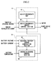
- FIG. 1 shows a block diagram of the motor control apparatus 4 and the battery control apparatus 9 shown in Figure 1.
- a reference numeral 41 relates to an assist/regenerate map to store control values for controlling generation or regeneration of assisting drive for engine 1.
- the term "assist” is used to mean assisting the drive power of the engine 1
- “regenerate” means to store regenerated power generated by the regeneration operation of the motor 2.
- the assist/regenerate map 41 defines the values to control when to generate assisting power or when to control the regeneration operation according to the degree of opening of the throttle and the revolution speed of the engine 1.
- the residual battery charge computation section 91 computes residual battery charge by integrating the charge/discharge current detected by the current sensor provided for the battery 8.
- the residual battery charge computation section 91 carries out correction (reset) of the residual battery charge computed by integrating charge/discharge current detected by the voltage sensor provided for the battery 8. Correction (reset) of residual battery charge for the battery 8 is carried out to eliminate the integration error resulting from integrating the charge/discharge current.
- a reference numeral 92 relates to a charge/discharge control section for determining the permissible amounts of charge/discharge according to battery temperature and residual battery charge of the battery 8 and informing the assist/regenerate amount control section 42 of the determined
- the engine 1 is provided with a throttle opening degree sensor and an engine revolution sensor, which are not shown, and the output signals from these sensors are input into the motor control apparatus 4.
- the battery 8 is provided with a voltage sensor and a temperature sensor, which are not shown, and the output signals from these sensors are input into the battery control apparatus 9.
- Residual battery charge for battery 8 is determined by a value computed by the battery control apparatus 9 with reference to battery voltage, charge/discharge current and battery temperature and the like.
- the battery control apparatus 9 controls the amount of charging or discharging the battery 8 according to the computed values of the residual battery charge. Control action is divided into three regions according to the levels of residual battery charge: a charging not-permitted region; a discharging not-permitted region and a use-permitted region.
- the charging not-permitted region is a region where there is a possibility of over-charging if charging is continued, and the level of residual battery charge in this region is 80 ⁇ 100 % of the fully charged battery, for example.
- the discharging not-permitted region is a region where capacity can be totally exhausted by excessive drainage if discharging is continued, and the level of residual battery charge in this region is 0 ⁇ 20 %, for example.
- the use-permitted region is a region where charging and discharging are both permitted, and the level of residual battery charge in this region is 20 ⁇ 80 %, for example.
- the battery control apparatus 9 controls the process of charging and discharging so as to preserve the residual battery charge in the use-permitted region.
- the boundary values of these regions are dependent on the characteristics of the battery used. Battery voltage and the residual battery charge are correlated such that as the battery residual charge increases the battery voltage increases. When the residual battery charge is intermediate (20 ⁇ 80 %), changes in battery voltage is small for changes in the levels of residual battery charge, but when the residual battery charge exceeds a top threshold value (about 80 %), increase in the battery voltage becomes extreme, and when the residual battery charge drops below a lowest threshold value (about 20%), decrease in the residual battery voltage becomes extreme. Therefore, residual battery charge may be estimated by detecting the phenomenon of excessively high or low battery voltage.
- the residual battery charge within the use-permitted region is computed by integrating the charged and discharged amounts of the battery 8.
- the method of computation using integration of current includes errors caused by current detection measurements so that the boundaries of use-permitted region cannot be detected precisely, and there is a high degree of error associated with the results of computation of residual battery charge when the battery is continually operated within the use-permitted region.
- the residual battery charge computed by the method of current integration is reset (revised) using correction values so as to eliminate detection errors of residual battery charge caused by errors associated with integration of charging/discharging currents.
- This integration error is reset when the increase or decrease in the battery voltage becomes excessive, by revising the residual battery charge with a threshold value (in this case, 20 or 80 %).
- the residual battery charge computation section 91 pre-stores values of the high and lower limits of battery voltage to correspond to the residual battery charge at the threshold values in a three-dimensional map, 3-D map, (not shown), constituted by three axes: voltage, battery temperature and battery discharge current.
- the residual battery charge computation section 91 obtains a battery voltage to correspond to the threshold values of the residual battery charge, according to the existing battery temperature and battery discharge current by referring to the 3-D map.
- the residual battery charge is revised according to the battery voltage thus obtained.
- Figure 4 shows a flowchart of the operation of the residual battery charge computation section 91.
- the residual battery charge computation section 91 detects the voltage of the battery 8 (Step S11). This voltage detection is performed according to output data from a voltage sensor (not shown).
- the residual battery charge computation section 91 determines whether the detected voltage is lower than the lower limit of battery voltage (step S12).
- the lower limit of battery voltage referred here is a voltage value obtained by referring to the 3-D map with axes of battery voltage, battery temperature and battery discharge current, and represents a value of the battery voltage when the residual battery charge reaches the low threshold level.
- the residual battery charge computation section 91 determines whether the detected battery voltage is higher than the high-limit voltage (step S13).
- the high-limit voltage referred here is a voltage value obtained by referring to the 3-D map with axes of battery voltage, battery temperature and battery discharge current, and represents a value of the battery voltage when the residual battery charge reaches the high threshold level.
- the residual battery charge computation section 91 determines charging/ discharge current (step S14).
- the detection of charging/discharging current is carried out by using the output data from the current sensor, and detects charging current separately from the discharging current.
- the residual battery charge computation section 91 integrates charging/ discharging current detected in step S14 (step S15). This integration process is carried out separately for charged amount and discharged amount, so that when the battery 8 is discharging, the discharged current is subtracted, but when the battery 8 is being charged, a value obtained by multiplying the detected current with a charging efficiency (0.95, for example) is added to the integral.
- the residual battery charge computation section 91 computes the existing residual battery charge according to the integrated value of the charging/discharging current and the initial value of the residual battery charge (step S16).
- the initial value of the residual battery charge is stored in the residual battery charge computation section 91 and is the residual battery charge renewed for every process of Figure 4. Further, the initial value is stored in the residual battery charge computation section 91 even when the ignition switch of the vehicle is turned off, and the stored initial value of the residual battery charge is read out when the ignition switch is turned on.
- step S12 if the battery voltage is less than the lower limit of battery voltage, the residual battery charge computation section 91 replaces the existing residual battery charge with the use-permitted low-limit (step S19).
- the use-permitted low-limit refers to the low-limit of residual charge in the use-permitted region described previously, and in this example, the value of the low-limit of residual charge is set at 20 %. Accordingly, the residual battery charge is revised to the lowest limit in the use-permitted region, and the integrated value of charging/discharging current is reset.
- step S13 if the battery voltage is higher than the upper-limit of battery voltage, the residual battery charge computation section 91 replaces the existing residual battery charge with the use-permitted high-limit (step S18).
- the of use-permitted high-limit refers to the high-limit of residual charge in the use-permitted region described previously, and in this example, the value of the high-limit of residual charge is set at 80 %. Accordingly, the residual battery charge is revised to the highest value in the use-permitted region, and the integrated value of charging/ discharging current is reset.
- the residual battery charge computation section 91 outputs the values of the residual battery charge computed or reset in step S16, S18, S19 to the charge/recharge control section 92 (step S17).
- the residual battery charge computation section 91 executes the steps from step S11 to S19, shown in Figure 4, at constant regular intervals. This constant interval is determined by the length of time required to carry out detection of battery voltage, and detection of charging/discharging current and computing a value of the integrated current.
- residual battery charge of battery 8 is computed or revised by detecting the voltage of battery 8 or integrating the charging/discharging current in the residual battery charge computation section 91, and the computed result is sent to the charge/discharge control section 92.
- output values of residual battery charge are in a range of 20 ⁇ 80 %.
- the charge/discharge control section 92 reads the residual battery charge output from the residual battery charge computation section 91, and controls charge/discharge actions according to the output value of the residual battery charge.
- Figure 3 shows a flowchart of the process of controlling charge/discharge action of the battery control section 9.
- the charge/discharge control section 92 determines whether the temperature of the battery 8 is higher than a specific temperature Tb1 (50 °C, for example) according to the output data of a temperature sensor (not shown) (step S1).
- FIG. 5 shows charging efficiency characteristics of battery 8.
- x-axis relates to the surface temperature of the module comprising the battery 8
- y-axis relates to charging efficiency of the battery 8.
- Charging efficiency refers to a ratio of attempted input of electrical energy and actually stored amount of electrical energy in the battery, and a value of 80 % for the charging efficiency means that 20 % of the electrical energy input into the battery 8 has been converted to heat.
- the charging efficiency of battery 8 begins to decrease rapidly when the surface temperature of the battery 8 reaches 50 °C.
- the temperature Tb1 is set to 50 °C, but the actual value is dependent on the characteristics of the battery installed in a vehicle so that the temperature Tb1 should be determined according to the actual value.
- step S1 if the battery temperature is not higher than the regulation temperature Tb1, the charge/discharge control section 92 outputs a command to the assist/regenerate amount control section 42 to operate normal charge/discharge operation. Accordingly, the assist/regenerate amount control section 42 carries out charge/discharge operation appropriate to normal assist or regenerate process with reference to the assist/regenerate map 41 (step S10).
- the normal charge/discharge operation means to perform control actions in compliance with the assist/regenerate map to maintain the residual battery charge in the range of 20 ⁇ 80 %, so that "assist" is not permitted when the residual battery charge is less than 20 %, and "regenerate” is not permitted when the residual battery charge is higher than 80 %.
- the charge/discharge control section 92 outputs a command to the assist/regenerate amount control section 42 to restrict the amount of charging so that the current value of the residual battery charge would be reduced (step S2).
- the command "to restrict the amount of charging” means to forbid regeneration, that is, to forbid any charging action. Therefore, the assist/regenerate amount control section 42 carries out the assist action only to the power drive unit 7 and the motor 2.
- the charge/discharge control section 92 obtains a value of the residual battery charge of the battery 8 computed in the residual battery charge computation section 91, and compares the computed value with the value of the use-permitted low-limit of the residual charge pre-stored in the charge/discharge control section 92 (step S3).
- the use-permitted low-limit of the residual charge means the lowest limit of the use-permitted region described previously, and in this example, the value of the low-limit of residual battery charge is set at 20 %.
- step S2 If the result of the comparison indicates that the existing residual battery charge is not less than 20 %, the flow returns to step S2, and repeats the process until the residual charge reaches less than 20 %.
- the residual battery charge is forced to the low-limit of use-permitted region, thereby correcting integration error caused in the current integration process.
- the charge/discharge control section 92 resets the internal timer (step S4).
- the charge/discharge control section 92 controls current in the charging/ discharging process by restricting the range of the residual battery charge.
- restrict means to revise the high-limit of use-permitted region described above with a restriction value that is less than the upper limit of the use-permitted region, and permit charging/discharging process to take place in a range not exceeding this revised restriction value. Because the restriction value cannot be detected by measuring the battery voltage, the process is controlled by detecting the integrated value of the charge/discharge current.
- This restriction value represents a high-limit of residual battery charge that enables to charge the battery without lowering the charging efficiency even when the battery temperature is high.
- this restriction value is set at the residual battery charge of 35 %, which is termed charge-permitted high-limit.
- Figure 6 shows values of the charging efficiency when the battery temperature is 25, 40, 45, 50 and 55 °C.
- x-axis relates to the applied charge amount and y-axis relates to the actual stored amount in the battery.
- the charge/discharge control section 92 obtains a computed value of the residual battery charge in the residual battery charge computation section 91, and compares the computed value with the use-permitted low-limit of the residual charge pre-stored in the charge/discharge control section 92 (step S6). If the result of comparison determines that the residual battery charge is less than 20 %, the flow returns to step S4, and again resets the internal timer.
- step S6 determines whether the temperature of the battery 8 is less than a pre-determined regulation temperature Tb2 according to the output data from the temperature sensor (not shown) (step S7).
- this regulation temperature is set at 48 °C. If the result the determines that the temperature is less than Tb2 (48 °C), the flow proceeds to step S10, and normal charge/discharge control is performed and the charging process is finished.
- the charge/discharge control section 92 obtains an elapsed time from the internal timer (step S8), and determines whether the obtained time exceeds a pre-determined regulation time (step S9). If the result determines that the time is not exceeded, the flow returns to step S5, and the same process is repeated until the specified regulation time is reached.
- the "regulation time” means an integration processing time required to reach a value that the integration error of the residual battery charge computed by current integration process does not exceed a pre-estimated range of integration error.
- step S9 if the elapsed time recorded by the internal timer has exceeded the regulation time, the flow returns to step S2, and repeats the process described earlier.
- the determination process in step S9 is performed so that the residual battery charge will be forced to the low-limit of the use-permitted region, because the integration error increases if the further integration process is continued to determine the residual battery charge.
- step S5 because only the current integration process is capable of detecting that the residual battery charge has reached a value of 35 %, the battery is forced to discharge to the 20 % level before the integration error is reset and charging/ discharging is permitted to retain the residual battery charge within a desirable range (20 ⁇ 35 % in this example). By so doing, it is possible to prevent a situation from developing that charging is accidentally continued until the residual battery charge exceeds the charge-permitted high-limit (35 %) due to increase in the integration error.
- the battery control apparatus 9 repeats the processing steps S1 ⁇ S10 shown in Figure 3.
- the process may be designed so that the range of residual battery charge for controlling the charging process may be determined according to the map shown in Figure 7.
- the map shown in Figure 7 defines the values of charge-permitted restriction value (35 % in the foregoing example), for restricting the upper limit of the use-permitted region, for each battery temperature. This map indicates that the charge-permitted restriction value increases as the battery temperature decreases,. Also, it is permissible that the map is used to define the restriction value for restricting the low-limit of the use-permitted region.
- step S2 when it is desired to restrict the charging amount in step S2, instead of stopping charging completely, it is permissible to control charge/discharge process so that the charging current supplied is less than the discharging current spent in the assist action of the motor 2, resulting that the residual battery charge is allowed to drop slowly to the low-limit of residual battery charge.
- the main battery 8 supplies the current flowing from the spare battery 11 through the downverter 10 to the electrical devices installed in the vehicle, the battery 8 may be regenerated within the existing power consumption level.
- heat generation in the battery can be prevented even when the battery temperature is high, because the charging/discharging process is carried out so as to limit the residual battery charge to remain in a suitable low range to avoid charging the battery in a region of low charging efficiency. Also, it is possible to reduce variations in the battery capacity among the modules comprising the battery.
- the present invention relates a battery control apparatus (9) controls charge/discharge processes of a battery (8) installed in a hybrid vehicle, according to the battery temperature so as to prevent degradation of the battery performance.
- the vehicle has a combustion engine (1) for providing a driving force, an electric motor (2) for generating a drive assist force for assisting the output of the engine, wherein the battery supplies electrical power to the motor, and, when the drive-assist force is not required by the engine, the motor is used as a generator to charged the battery
- the apparatus is comprised by: a residual battery charge computation device (91) for computing a level of residual battery charge in the battery; a battery temperature measuring device for measuring a temperature of the battery; and a charge/discharge controller (92) that operates in such a way that, when a battery temperature measured by the battery temperature measuring device exceeds a threshold temperature, the charge/discharge controller permits only discharging until the residual battery charge is lowered to a level defined by a first specified value.
Landscapes
- Engineering & Computer Science (AREA)
- Transportation (AREA)
- Mechanical Engineering (AREA)
- Chemical & Material Sciences (AREA)
- Combustion & Propulsion (AREA)
- Power Engineering (AREA)
- Life Sciences & Earth Sciences (AREA)
- Sustainable Development (AREA)
- Sustainable Energy (AREA)
- Electric Propulsion And Braking For Vehicles (AREA)
- Charge And Discharge Circuits For Batteries Or The Like (AREA)
- Hybrid Electric Vehicles (AREA)
Abstract
Description
Claims (3)
- An apparatus (9) for controlling a battery (8) installed in a hybrid vehicle having a combustion engine (1) for providing a driving force, an electric motor (2) for generating a drive-assist force for assisting the output of the engine, wherein said battery supplies electrical power to the motor, and, when the drive-assist force is not required by the engine, said motor is used as a generator to charged the battery, said apparatus is comprised by:a residual battery charge computation device (91) for computing a level of residual battery charge in the battery;a battery temperature measuring device for measuring a temperature of the battery; anda charge/discharge controller (92) that operates in such a way that, when a battery temperature measured by the battery temperature measuring device exceeds a threshold temperature, said charge/discharge controller permits only discharging until the residual battery charge is lowered to a level defined by a first specified value.
- An apparatus according to claim 1, wherein, after said battery reaches said first specified value of residual battery charge, said charge/discharge controller permits the battery to be charged a level not exceeding a level defined by a second specified value of the residual battery charge, which is higher than said first specified value of the residual battery charge.
- An apparatus according to one of claim 1 or 2, wherein the residual battery charge computation device determines whether a battery voltage is at a low-limit of the battery voltage, and defines a detected low-limit of battery voltage as representing the use-permitted low-limit of the residual battery charge.
Applications Claiming Priority (2)
| Application Number | Priority Date | Filing Date | Title |
|---|---|---|---|
| JP24235499A JP3926518B2 (en) | 1999-08-27 | 1999-08-27 | Battery control device for hybrid vehicle |
| JP24235499 | 1999-08-27 |
Publications (3)
| Publication Number | Publication Date |
|---|---|
| EP1079494A2 true EP1079494A2 (en) | 2001-02-28 |
| EP1079494A3 EP1079494A3 (en) | 2004-04-21 |
| EP1079494B1 EP1079494B1 (en) | 2005-06-01 |
Family
ID=17087954
Family Applications (1)
| Application Number | Title | Priority Date | Filing Date |
|---|---|---|---|
| EP00118530A Expired - Lifetime EP1079494B1 (en) | 1999-08-27 | 2000-08-25 | Battery control apparatus for hybrid vehicle |
Country Status (4)
| Country | Link |
|---|---|
| US (1) | US6232748B1 (en) |
| EP (1) | EP1079494B1 (en) |
| JP (1) | JP3926518B2 (en) |
| DE (1) | DE60020459T2 (en) |
Cited By (10)
| Publication number | Priority date | Publication date | Assignee | Title |
|---|---|---|---|---|
| EP1319548A3 (en) * | 2001-12-12 | 2004-02-11 | Honda Giken Kogyo Kabushiki Kaisha | Hybrid vehicle and control method therefor |
| WO2004108468A1 (en) * | 2003-06-03 | 2004-12-16 | Toyota Jidosha Kabushiki Kaisha | Onboard battery control device and control method |
| GB2411058A (en) * | 2001-11-12 | 2005-08-17 | Hewlett Packard Co | Battery charging and discharging system |
| DE102007020935A1 (en) * | 2007-05-04 | 2008-11-06 | Volkswagen Ag | Method and device for the drive control of hybrid vehicles at high load of an electronic energy storage |
| CN107878212A (en) * | 2017-10-31 | 2018-04-06 | 吉利汽车研究院(宁波)有限公司 | A kind of automobile storage battery preventing electric loss guard method and system |
| CN109935920A (en) * | 2017-12-16 | 2019-06-25 | 神讯电脑(昆山)有限公司 | The discharge control method and battery circuit framework of battery |
| CN110650859A (en) * | 2017-06-21 | 2020-01-03 | 宝马股份公司 | Energy supply device for a motor vehicle |
| CN111181214A (en) * | 2020-01-19 | 2020-05-19 | 威海安屯尼智能电子科技有限公司 | Charging method of lithium ion charger based on temperature detection |
| CN111347923A (en) * | 2018-12-20 | 2020-06-30 | 北汽福田汽车股份有限公司 | Battery early warning method and device and vehicle |
| US11661165B1 (en) * | 2017-01-11 | 2023-05-30 | Brunswick Corporation | PCM controlled charging system |
Families Citing this family (33)
| Publication number | Priority date | Publication date | Assignee | Title |
|---|---|---|---|---|
| US6554088B2 (en) | 1998-09-14 | 2003-04-29 | Paice Corporation | Hybrid vehicles |
| JP3377040B2 (en) * | 1999-10-08 | 2003-02-17 | トヨタ自動車株式会社 | Hybrid vehicle control device |
| JP2001275205A (en) * | 2000-03-24 | 2001-10-05 | Nissan Motor Co Ltd | Control device for combined use system of secondary battery and generator |
| DE10104981A1 (en) * | 2001-02-03 | 2002-08-08 | Varta Geraetebatterie Gmbh | Procedure for monitoring the operational safety of rechargeable Li cells |
| JP2002330554A (en) * | 2001-04-27 | 2002-11-15 | Kobelco Contstruction Machinery Ltd | Power control device for hybrid vehicle and hybrid construction machine equipped with the power control device |
| JP3750608B2 (en) * | 2002-01-23 | 2006-03-01 | トヨタ自動車株式会社 | Control device for power storage device in vehicle |
| JP3854175B2 (en) * | 2002-03-01 | 2006-12-06 | インターナショナル・ビジネス・マシーンズ・コーポレーション | ELECTRIC DEVICE, COMPUTER DEVICE, CONTROLLER, BATTERY SWITCHING METHOD, AND PROGRAM |
| KR100456845B1 (en) * | 2002-05-20 | 2004-11-10 | 현대자동차주식회사 | Interface apparatus of on hybrid electric vehicle |
| US6809428B1 (en) | 2002-06-21 | 2004-10-26 | Dana Corporation | Overheat protection of an electrical component of an I.C. engine |
| JP3839382B2 (en) * | 2002-09-13 | 2006-11-01 | 本田技研工業株式会社 | Control device for in-vehicle power storage device |
| US6727670B1 (en) | 2002-12-12 | 2004-04-27 | Ford Global Technologies, Llc | Battery current limiter for a high voltage battery pack in a hybrid electric vehicle powertrain |
| US7348763B1 (en) * | 2002-12-20 | 2008-03-25 | Linvatec Corporation | Method for utilizing temperature to determine a battery state |
| US7234552B2 (en) * | 2003-09-19 | 2007-06-26 | Ford Global Technologies, Llc | Method for heating a battery in a hybrid electric vehicle |
| US7155075B2 (en) * | 2004-03-29 | 2006-12-26 | General Electric Company | Optical battery temperature monitoring system and method |
| JP2007064209A (en) * | 2005-08-05 | 2007-03-15 | Fujitsu Ten Ltd | Engine control device, control method, and control system |
| JP4209423B2 (en) * | 2005-12-16 | 2009-01-14 | パナソニックEvエナジー株式会社 | Secondary battery control device and secondary battery output control method |
| JP4337848B2 (en) * | 2006-07-10 | 2009-09-30 | トヨタ自動車株式会社 | Power supply system, vehicle including the same, and temperature management method |
| JP4678353B2 (en) * | 2006-09-29 | 2011-04-27 | コベルコ建機株式会社 | Hybrid work machine |
| JP2008189236A (en) * | 2007-02-07 | 2008-08-21 | Fuji Heavy Ind Ltd | Control device for hybrid vehicle |
| JP4798092B2 (en) * | 2007-07-23 | 2011-10-19 | 三菱自動車工業株式会社 | Electric vehicle braking system |
| DE102008060954B4 (en) * | 2008-12-06 | 2023-03-09 | Bayerische Motoren Werke Aktiengesellschaft | Method for regulating or controlling the state of charge of an electrical energy store of a hybrid vehicle |
| FR2963167B1 (en) * | 2010-07-20 | 2013-03-08 | Peugeot Citroen Automobiles Sa | DEVICE AND METHOD FOR COOLING A MEANS FOR STORING ELECTRIC ENERGY |
| CN103249623B (en) * | 2010-12-09 | 2016-02-10 | 沃尔沃卡车集团 | For controlling the method for hybrid vehicle and being suitable for the hybrid vehicle of the method |
| US8473177B2 (en) * | 2010-12-31 | 2013-06-25 | Cummins, Inc. | Apparatuses, methods, and systems for thermal management of hybrid vehicle SCR aftertreatment |
| JP5747986B2 (en) | 2011-08-03 | 2015-07-15 | トヨタ自動車株式会社 | Hybrid vehicle and control method thereof |
| JP6013227B2 (en) * | 2013-02-22 | 2016-10-25 | 株式会社東芝 | Power storage device |
| JP6233856B2 (en) * | 2013-08-09 | 2017-11-22 | 日立オートモティブシステムズ株式会社 | Battery control system, vehicle control system |
| JP2017226284A (en) * | 2016-06-21 | 2017-12-28 | 株式会社クボタ | Working machine |
| JP7122186B2 (en) * | 2018-07-13 | 2022-08-19 | 日野自動車株式会社 | motor controller |
| US11014437B2 (en) | 2018-09-10 | 2021-05-25 | Toyota Motor Engineering & Manufacturing North America, Inc. | Hybrid electric vehicle battery charge reduction for improved cooling performance |
| US12062937B2 (en) * | 2020-09-15 | 2024-08-13 | Panasonic Intellectual Property Management Co., Ltd. | Method of controlling secondary battery and battery system |
| CN216101961U (en) * | 2021-05-26 | 2022-03-22 | 上汽通用五菱汽车股份有限公司 | Quick complementary system of battery insufficient voltage |
| CN115257592B (en) * | 2022-07-29 | 2024-05-14 | 重庆长安汽车股份有限公司 | Control method and system for reminding user to charge storage battery |
Family Cites Families (7)
| Publication number | Priority date | Publication date | Assignee | Title |
|---|---|---|---|---|
| FR2672736B1 (en) * | 1991-02-08 | 1993-04-16 | Accumulateurs Fixes | METHOD FOR OPTIMIZING THE CHARGE OF A BATTERY, AND DEVICE FOR CARRYING OUT SAID METHOD. |
| US5412307A (en) * | 1992-06-09 | 1995-05-02 | Sony Corporation | Residual capacity indicating device |
| JP2878953B2 (en) * | 1993-12-27 | 1999-04-05 | 本田技研工業株式会社 | Method for detecting remaining capacity of battery for electric vehicle |
| DE4403468C2 (en) * | 1994-02-04 | 1998-07-09 | Daimler Benz Ag | Withdrawal current monitoring system for traction batteries in electric and hybrid vehicles |
| FR2739724B1 (en) * | 1995-10-05 | 1997-11-14 | Accumulateurs Fixes | METHOD FOR CHARGING WATERPROOF NICKEL-CADMIUM BATTERIES |
| US5825159A (en) * | 1997-09-29 | 1998-10-20 | Motorola, Inc. | Battery charging method for properly terminating rapid charge |
| JP3680898B2 (en) * | 1997-10-13 | 2005-08-10 | トヨタ自動車株式会社 | Secondary battery charge / discharge controller |
-
1999
- 1999-08-27 JP JP24235499A patent/JP3926518B2/en not_active Expired - Lifetime
-
2000
- 2000-08-24 US US09/644,768 patent/US6232748B1/en not_active Expired - Lifetime
- 2000-08-25 EP EP00118530A patent/EP1079494B1/en not_active Expired - Lifetime
- 2000-08-25 DE DE60020459T patent/DE60020459T2/en not_active Expired - Lifetime
Cited By (12)
| Publication number | Priority date | Publication date | Assignee | Title |
|---|---|---|---|---|
| GB2411058A (en) * | 2001-11-12 | 2005-08-17 | Hewlett Packard Co | Battery charging and discharging system |
| GB2411058B (en) * | 2001-11-12 | 2005-11-30 | Hewlett Packard Co | Battery charging and discharging system |
| EP1319548A3 (en) * | 2001-12-12 | 2004-02-11 | Honda Giken Kogyo Kabushiki Kaisha | Hybrid vehicle and control method therefor |
| WO2004108468A1 (en) * | 2003-06-03 | 2004-12-16 | Toyota Jidosha Kabushiki Kaisha | Onboard battery control device and control method |
| DE102007020935A1 (en) * | 2007-05-04 | 2008-11-06 | Volkswagen Ag | Method and device for the drive control of hybrid vehicles at high load of an electronic energy storage |
| US11661165B1 (en) * | 2017-01-11 | 2023-05-30 | Brunswick Corporation | PCM controlled charging system |
| CN110650859A (en) * | 2017-06-21 | 2020-01-03 | 宝马股份公司 | Energy supply device for a motor vehicle |
| CN110650859B (en) * | 2017-06-21 | 2023-10-20 | 宝马股份公司 | Energy supply device for motor vehicles |
| CN107878212A (en) * | 2017-10-31 | 2018-04-06 | 吉利汽车研究院(宁波)有限公司 | A kind of automobile storage battery preventing electric loss guard method and system |
| CN109935920A (en) * | 2017-12-16 | 2019-06-25 | 神讯电脑(昆山)有限公司 | The discharge control method and battery circuit framework of battery |
| CN111347923A (en) * | 2018-12-20 | 2020-06-30 | 北汽福田汽车股份有限公司 | Battery early warning method and device and vehicle |
| CN111181214A (en) * | 2020-01-19 | 2020-05-19 | 威海安屯尼智能电子科技有限公司 | Charging method of lithium ion charger based on temperature detection |
Also Published As
| Publication number | Publication date |
|---|---|
| US6232748B1 (en) | 2001-05-15 |
| DE60020459T2 (en) | 2005-10-13 |
| EP1079494B1 (en) | 2005-06-01 |
| JP2001069602A (en) | 2001-03-16 |
| EP1079494A3 (en) | 2004-04-21 |
| DE60020459D1 (en) | 2005-07-07 |
| JP3926518B2 (en) | 2007-06-06 |
Similar Documents
| Publication | Publication Date | Title |
|---|---|---|
| EP1079494B1 (en) | Battery control apparatus for hybrid vehicle | |
| US6225784B1 (en) | Battery control apparatus for battery carried by hybrid vehicle | |
| JP3560867B2 (en) | Hybrid vehicle battery control device | |
| US6501250B2 (en) | Device and method for controlling input/output of secondary battery | |
| JP3857146B2 (en) | Control device for hybrid vehicle | |
| US7479761B2 (en) | Secondary battery control apparatus and control method for predicting charging in regenerative braking | |
| US7019472B2 (en) | Vehicle controller that stably supplies power to a battery and method thereof | |
| JP5547699B2 (en) | Vehicle drive device | |
| JP5054338B2 (en) | VEHICLE POWER SUPPLY CONTROL DEVICE AND ITS CONTROL METHOD | |
| US7091626B2 (en) | Method for regulating the generator voltage in a motor vehicle | |
| JP5493407B2 (en) | Battery pack capacity adjustment device | |
| JPH07123509A (en) | Controller for generator motor for internal combustion engine | |
| JP2004328906A (en) | Hybrid vehicle charge control device | |
| JP2004248405A (en) | Vehicle battery management device | |
| JP3700531B2 (en) | Control device for hybrid vehicle | |
| CN115214613A (en) | Hybrid vehicle parallel drive control method, device, device and storage medium | |
| JP2004003460A (en) | Vehicle control device and control method | |
| JP3838233B2 (en) | Storage device control device | |
| JP2003153402A (en) | Secondary battery control device | |
| JP5954188B2 (en) | Secondary battery management device | |
| JP4188271B2 (en) | Vehicle battery management device | |
| KR102602915B1 (en) | System and method for controlling charging torque of hybrid vehicle | |
| JP3774790B2 (en) | Regenerative control device for hybrid vehicle | |
| JP3772876B2 (en) | Control device for hybrid vehicle | |
| JP5169479B2 (en) | Vehicle control device |
Legal Events
| Date | Code | Title | Description |
|---|---|---|---|
| PUAI | Public reference made under article 153(3) epc to a published international application that has entered the european phase |
Free format text: ORIGINAL CODE: 0009012 |
|
| AK | Designated contracting states |
Kind code of ref document: A2 Designated state(s): AT BE CH CY DE DK ES FI FR GB GR IE IT LI LU MC NL PT SE |
|
| AX | Request for extension of the european patent |
Free format text: AL;LT;LV;MK;RO;SI |
|
| PUAL | Search report despatched |
Free format text: ORIGINAL CODE: 0009013 |
|
| AK | Designated contracting states |
Kind code of ref document: A3 Designated state(s): AT BE CH CY DE DK ES FI FR GB GR IE IT LI LU MC NL PT SE |
|
| AX | Request for extension of the european patent |
Extension state: AL LT LV MK RO SI |
|
| RIC1 | Information provided on ipc code assigned before grant |
Ipc: 7H 02J 7/00 B Ipc: 7B 60L 11/18 A |
|
| 17P | Request for examination filed |
Effective date: 20040803 |
|
| GRAP | Despatch of communication of intention to grant a patent |
Free format text: ORIGINAL CODE: EPIDOSNIGR1 |
|
| AKX | Designation fees paid |
Designated state(s): DE GB |
|
| GRAS | Grant fee paid |
Free format text: ORIGINAL CODE: EPIDOSNIGR3 |
|
| GRAA | (expected) grant |
Free format text: ORIGINAL CODE: 0009210 |
|
| AK | Designated contracting states |
Kind code of ref document: B1 Designated state(s): DE GB |
|
| REG | Reference to a national code |
Ref country code: GB Ref legal event code: FG4D |
|
| REG | Reference to a national code |
Ref country code: IE Ref legal event code: FG4D |
|
| REF | Corresponds to: |
Ref document number: 60020459 Country of ref document: DE Date of ref document: 20050707 Kind code of ref document: P |
|
| PLBE | No opposition filed within time limit |
Free format text: ORIGINAL CODE: 0009261 |
|
| STAA | Information on the status of an ep patent application or granted ep patent |
Free format text: STATUS: NO OPPOSITION FILED WITHIN TIME LIMIT |
|
| 26N | No opposition filed |
Effective date: 20060302 |
|
| REG | Reference to a national code |
Ref country code: GB Ref legal event code: 746 Effective date: 20140502 |
|
| REG | Reference to a national code |
Ref country code: DE Ref legal event code: R084 Ref document number: 60020459 Country of ref document: DE Effective date: 20140428 |
|
| REG | Reference to a national code |
Ref country code: DE Ref legal event code: R079 Ref document number: 60020459 Country of ref document: DE Free format text: PREVIOUS MAIN CLASS: B60L0011180000 Ipc: B60L0050500000 |
|
| PGFP | Annual fee paid to national office [announced via postgrant information from national office to epo] |
Ref country code: DE Payment date: 20190813 Year of fee payment: 20 |
|
| PGFP | Annual fee paid to national office [announced via postgrant information from national office to epo] |
Ref country code: GB Payment date: 20190822 Year of fee payment: 20 |
|
| REG | Reference to a national code |
Ref country code: DE Ref legal event code: R071 Ref document number: 60020459 Country of ref document: DE |
|
| REG | Reference to a national code |
Ref country code: GB Ref legal event code: PE20 Expiry date: 20200824 |
|
| PG25 | Lapsed in a contracting state [announced via postgrant information from national office to epo] |
Ref country code: GB Free format text: LAPSE BECAUSE OF EXPIRATION OF PROTECTION Effective date: 20200824 |