EP1079252A2 - Apparatus and method for laterally displacing an optical signal - Google Patents
Apparatus and method for laterally displacing an optical signal Download PDFInfo
- Publication number
- EP1079252A2 EP1079252A2 EP00306928A EP00306928A EP1079252A2 EP 1079252 A2 EP1079252 A2 EP 1079252A2 EP 00306928 A EP00306928 A EP 00306928A EP 00306928 A EP00306928 A EP 00306928A EP 1079252 A2 EP1079252 A2 EP 1079252A2
- Authority
- EP
- European Patent Office
- Prior art keywords
- optical
- guiding element
- optical guiding
- receiving
- transmission
- Prior art date
- Legal status (The legal status is an assumption and is not a legal conclusion. Google has not performed a legal analysis and makes no representation as to the accuracy of the status listed.)
- Withdrawn
Links
Images


Classifications
-
- G—PHYSICS
- G02—OPTICS
- G02B—OPTICAL ELEMENTS, SYSTEMS OR APPARATUS
- G02B6/00—Light guides; Structural details of arrangements comprising light guides and other optical elements, e.g. couplings
- G02B6/24—Coupling light guides
- G02B6/26—Optical coupling means
- G02B6/28—Optical coupling means having data bus means, i.e. plural waveguides interconnected and providing an inherently bidirectional system by mixing and splitting signals
- G02B6/2804—Optical coupling means having data bus means, i.e. plural waveguides interconnected and providing an inherently bidirectional system by mixing and splitting signals forming multipart couplers without wavelength selective elements, e.g. "T" couplers, star couplers
- G02B6/2817—Optical coupling means having data bus means, i.e. plural waveguides interconnected and providing an inherently bidirectional system by mixing and splitting signals forming multipart couplers without wavelength selective elements, e.g. "T" couplers, star couplers using reflective elements to split or combine optical signals
-
- G—PHYSICS
- G02—OPTICS
- G02B—OPTICAL ELEMENTS, SYSTEMS OR APPARATUS
- G02B6/00—Light guides; Structural details of arrangements comprising light guides and other optical elements, e.g. couplings
- G02B6/24—Coupling light guides
- G02B6/26—Optical coupling means
- G02B6/262—Optical details of coupling light into, or out of, or between fibre ends, e.g. special fibre end shapes or associated optical elements
-
- G—PHYSICS
- G02—OPTICS
- G02B—OPTICAL ELEMENTS, SYSTEMS OR APPARATUS
- G02B6/00—Light guides; Structural details of arrangements comprising light guides and other optical elements, e.g. couplings
- G02B6/24—Coupling light guides
- G02B6/42—Coupling light guides with opto-electronic elements
- G02B6/4201—Packages, e.g. shape, construction, internal or external details
- G02B6/4246—Bidirectionally operating package structures
-
- G—PHYSICS
- G02—OPTICS
- G02B—OPTICAL ELEMENTS, SYSTEMS OR APPARATUS
- G02B6/00—Light guides; Structural details of arrangements comprising light guides and other optical elements, e.g. couplings
- G02B6/24—Coupling light guides
- G02B6/26—Optical coupling means
- G02B6/32—Optical coupling means having lens focusing means positioned between opposed fibre ends
-
- G—PHYSICS
- G02—OPTICS
- G02B—OPTICAL ELEMENTS, SYSTEMS OR APPARATUS
- G02B6/00—Light guides; Structural details of arrangements comprising light guides and other optical elements, e.g. couplings
- G02B6/24—Coupling light guides
- G02B6/42—Coupling light guides with opto-electronic elements
- G02B6/4201—Packages, e.g. shape, construction, internal or external details
- G02B6/4204—Packages, e.g. shape, construction, internal or external details the coupling comprising intermediate optical elements, e.g. lenses, holograms
- G02B6/4214—Packages, e.g. shape, construction, internal or external details the coupling comprising intermediate optical elements, e.g. lenses, holograms the intermediate optical element having redirecting reflective means, e.g. mirrors, prisms for deflecting the radiation from horizontal to down- or upward direction toward a device
-
- G—PHYSICS
- G02—OPTICS
- G02B—OPTICAL ELEMENTS, SYSTEMS OR APPARATUS
- G02B6/00—Light guides; Structural details of arrangements comprising light guides and other optical elements, e.g. couplings
- G02B6/24—Coupling light guides
- G02B6/42—Coupling light guides with opto-electronic elements
- G02B6/4201—Packages, e.g. shape, construction, internal or external details
- G02B6/4249—Packages, e.g. shape, construction, internal or external details comprising arrays of active devices and fibres
Definitions
- the invention relates to optical signal transmission. More particularly, the invention relates to an apparatus and method for steering or redirecting light beams within optical communications systems.
- Redirecting or steering an optical signal or beam within an optical communications system is accomplished by many conventional devices and for many different reasons. Often, optical signals are redirected to better align them with one or more components within the system. For example, optical signals often are redirected to better align with a detector or receiver after having passed through various system components. Also, because optical sources such as an edge or surface emitting laser or a light emitting diode (LED) and optical detectors such as semiconductor photodetectors and photodiodes often are oriented differently with respect to the path of light travel into or out of the particular device or package, optical beams often must be redirected for better alignment therewith.
- LED light emitting diode
- optical sources and detectors are packaged together as part of a transceiver or as part of multiple source/detector arrangements.
- the optical source and its corresponding detector often are side by side, with the distance between respective central axes thereof on the order of 5 millimeters (mm).
- at least a portion of an optical signal transmitted from an optical source of a first transceiver is transported to various system components including an optical receiver or detector from, for example, a second transceiver, while another optical signal is transported from a source of the second transceiver to, for example, the optical receiver/detector of the first transceiver.
- Conventional beam steering devices include devices that actively change the direction of transmitted or reflected beams using, for example, movable lens or mirror arrangements.
- Such active beam steering devices include, for example, U.S. Patent Nos. 4,961,627 and 5,600,741.
- active beam steering devices often are relatively expensive and bulky, as they typically require some mechanical means for providing translational or rotational motion to the lenses, mirrors and/or prisms.
- Such devices typically are geared toward applications that require relatively precise alignment tolerances.
- Conventional beam steering devices also include passive devices, such as substrates with grooves and reflective surfaces formed therein for aligning, for example, optical fibers and other waveguide structures for steering beams. See, for example, U.S. Patent No. 5,073,003, which is assigned to the assignee of this application, and U.S. Patent No. 5,600,741.
- Embodiments of the invention include an optical communications system including an apparatus and method for laterally displacing or otherwise steering optical signals passing therethrough.
- the system comprises a launching device for launching or transmitting an optical signal, a receiving device for receiving an optical signal, and at least one optical guiding element.
- the optical guiding element is a transmission medium that captures and transmits optical information therethrough and is configured, for example, via end geometries, to redirect a portion of light propagating in a first direction and entering the first end substantially along its transmission axis and to redirect light propagating along the transmission axis out of the second end in a desired direction, for example, a second direction laterally displaced from the first direction.
- the ends of the optical guiding element are angled faces with or without a reflective coating formed thereon.
- lenses are coupled to the ends opposite the angled faces.
- the transmission axis of the optical beam entering the optical guiding element and the optical beam exiting the optical guiding element are substantially parallel.
- the transmission axis of an optical beam coupled to the first end of an optical guiding element is laterally displaced to an optical element, for example, an optical fiber, coupled to the second end of the optical guiding element.
- an optical element for example, an optical fiber
- a pair of optical guiding elements aligned substantially coaxial and coupled at their first ends to an optical element, for example, an optical source work to increase the distance between the transmission axes of the launched and received optical signals.
- Such beam steering is advantageous, for example, in aligning beams launched into and out of source/detector packages with other components, including optical fibers.
- the optical communications system includes a power splitting arrangement comprising an optical signal launching device such as a single or multi-element optical source, a plurality of receiving devices such as optical fibers, and a plurality of optical guiding elements coupled between the launching device and the plurality of optical receiving devices.
- the power splitting arrangement couples the launching device to, for example, the first ends of the optical guiding elements and couples the plurality of receiving devices to, for example, the second ends of the plurality of optical guiding elements. In this manner, the optical information launched from the launching device is split into a plurality of signals for transmission through the optical guiding elements and on to, for example, the receiving devices.
- the optical communications system includes a multiplexing arrangement comprising a plurality of optical guiding elements coupled between an optical receiving device such as an optical fiber and a plurality of optical signal launching devices such optical sources.
- the multiplexing arrangement couples the receiving device to, for example, the first ends of the optical guiding elements and couples the plurality of launching devices to, for example, the second ends of the plurality of optical guiding elements.
- the optical signals passing (for example, at different wavelengths) from the plurality of launching optical sources are multiplexed into a composite optical signal that subsequently is coupled to the receiving device via the first ends of the optical guiding elements.
- the multiplexed optical signal is received by the receiving device.
- Embodiments of the invention are based on the advantageous realization that optical signals or optical beams are steered or redirected using one or more optical guiding element having appropriate configurations. More specifically, embodiments of the invention use one or more optical guiding elements to redirect optical signals in a manner that results in the optical signals being laterally shifted or laterally displaced. Such shifting is advantageous, for example, in arrangements within optical communications systems in which an optical beam transmitted from one or more launching devices is redirected to align with various components within the system, including one or more optical receiving devices such as optical fibers.
- the terms "shifting” or “laterally displacing” when referring to an optical beam is understood to mean redirecting an optical beam entering a first end of the optical guiding element substantially along the transmission axis of the optical guiding element and then redirecting the optical beam out of a second, opposing end of the optical guiding element.
- an optical beam is laterally displaced in such a manner that the resulting axis of transmission of the optical beam is substantially parallel to the original axis of transmission of the optical beam.
- the optical guiding element 10 is, for example, a rod-shaped optical transmission medium made of, for example, glass, plastic such as molded plastic or other suitable material or materials that adequately transmit optical signals.
- suitable material include, for example, polymethymethacrylate (pmma), polymethylpentene and other acrylics.
- the optical guiding element 10 is surrounded , at least partially, by a cladding layer having an index of refraction less than the index of refraction of the optical guiding element 10.
- the optical guiding element 10 includes a first end 12, a second end 14 (for example, opposing the first end 12), and an axis of transmission (shown generally as the x axis) running longitudinally therebetween.
- the optical guiding element 10 is configured with end geometries that generally reflect or redirect incoming optical signals along the axis of transmission of the optical guiding element.
- the end geometries of the optical guiding element 10 generally reflect or redirect optical signals traveling generally along the axis of transmission of the optical guiding element 10 out of the optical guiding element 10 at an appropriate angle.
- the first end 12 includes an angled face 16 or other means for reflecting incoming optical beams (shown generally as 17) transmitted from an optical launching device 22 generally along the axis of transmission of the optical guiding element 10.
- Typical launching devices 22 include, for example, optical sources or other optical transmitting devices such as lasers and light emitting diodes (LEDs), and other suitable devices such as optical fiber that carry optical signals.
- the angled face 16 is, for example, a highly reflective surface with an angle of approximately 45 degrees. Alternatively, the angled face 16 includes a reflective coating formed thereon.
- the second end 14 includes an angled face 18 for reflecting optical beams generally transmitted along the axis of transmission of the optical guiding element 10 out of the second end 14 toward an optical signal receiving element or device 24 (the redirected outgoing beam is shown generally as 19).
- Typical receiving devices 24 include, for example, an optical or opto-electronic detector such as semiconductor photodiodes, photodetectors or other suitable receiving elements such as optical fibers and optical connectors.
- optical beams traveling in a first direction and entering the first end 12 of the optical guiding element 10 are redirected, for example, by the angled face 16, generally along the axis of transmission of the optical guiding element 10.
- Such optical beams are redirected, for example, by the angled face 18, out of the second end 14 of the optical guiding element 10 in a second direction, which is laterally displaced from the first direction.
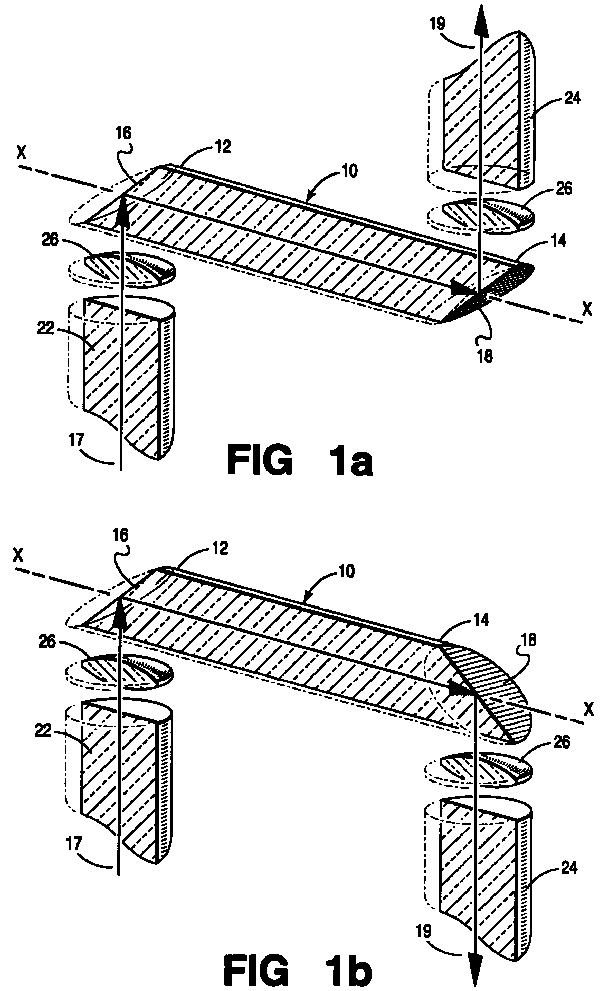
- the orientation of the angled faces 16, 18 with respect to one another determines the general direction of reflection of optical signals passing through the optical guiding element 10. For example, as shown in Fig. 1a, with angled faces 16, 18 generally parallel with respect to one another and angled at approximately 45 degrees with respect to the axis of transmission of the optical guiding element 10, optical signals entering and exiting the optical guiding element 10 are laterally displaced from one another but generally travel in the same direction. However, as shown in Fig. 1b, with angled faces 16, 18 generally complementary with respect to one another and having faces angled at approximately 45 degrees, optical signals entering and exiting the optical guiding element 10 are laterally displaced from one another but generally travel in opposite directions.
- any number of redirection combinations is possible according to embodiments of the invention.
- the angled face 18 at the second end 14 of the optical guiding element 10 may be oriented (rotationally about the longitudinal axis of the optical guiding element 10) with respect to the angled face 16 at the first end 12 of the optical guiding element 10 to redirect optical signals passing through the optical guiding element 10 in a direction generally orthogonal to an incoming optical signal 17.
- both angled faces 16, 18 shown in Figs. 1a and 1b are angled at approximately 45 degrees with respect to longitudinal axis of the optical guiding element 10 (and with respect to the angle of incidence of the incoming optical beam 17).
- optical guiding elements with angled faces less than or more than approximately 45 degrees less redirected light passes through the optical guiding element 10 from the first end 12 to the second end 14 and thus less redirected light is coupled from, for example, the launching device 22 to the receiving device 24.
- first and second angled faces 16, 18 it is possible for one or both of the first and second angled faces 16, 18 to be formed at any desired angle with respect to the axis of transmission of the optical guiding element 10 to redirect incoming and/or outgoing optical beams in any corresponding direction.
- the plane formed by the second angled face 18 has been rotated slightly about the z-axis.
- first and second ends of the optical guiding elements 10 operate in a similar manner with respect to redirecting optical signals and reference to their being “first" and “second” ends is arbitrary, an attempt is made herein to maintain consistency with respect to these references for purposes of enhancing the clarity of the discussion.
- the optical guiding elements discussed herein and shown in the figures mostly have a rod-like shape, it is possible for the optical guiding element to be configured as needed to achieve the desired beam displacement.
- the optical guiding element 10 it is possible for the optical guiding element 10 to be oval or rectangular, with a cross-section either round, oval or generally square.
- the first end 12 and/or second end 14 of the optical guiding element 10 includes a lens 26 or lens combination coupled thereto, as shown.
- the lenses 26 are, for example, refractive lenses (as shown generally) or, alternatively, are diffractive (not shown).
- the lenses 26 are shaped appropriately and coupled to the first end 12 to enhance the collection of optical beams entering optical guiding element 10 and/or coupled to the second end 14 to enhance the dispersion of optical beams exiting optical guiding element 10.
- the lenses 26 are shaped and coupled to the respective ends of the optical guiding element 10, for example, in a conventional manner.
- the optical guiding element 10 is coupled with respect to the launching device 22 and the receiving element 24, for example, as shown in Fig. 1.
- the optical guiding element 10 is aligned and oriented with respect to the launching device 22 in such a way that the launched optical signals enter the first end 12 of the optical guiding element 10 for redirection generally along the axis of transmission of the optical guiding element 10.
- the receiving element 24 is aligned and oriented with respect to the optical guiding element 10 in general and the second end 14 in particular in such a way that the outgoing optical signals are directed sufficiently at the receiving element 24 for appropriate reception thereof, for example, in a conventional manner.
- a pair of optical guiding elements 10 a , 10 b are used to laterally displace the transmission axes of an optical beam from a first launching device L 1 to a first receiving element R 1 and an optical beam to a second receiving element R 2 from a second launching device L 2 .
- Such embodiments are advantageous, for example, when coupling a source/detector package (shown generally as 28) to other component(s) not dimensioned as such.
- optical launching and optical receiving devices are packaged in off-the-shelf packages having separation between launching devices and receiving devices of approximately 100 to 1000 microns ( ⁇ m) center to center (for example, shown generally as the distance x shown in Fig. 2).
- ⁇ m microns
- elements including connectors used to interconnect optical components within optical communications systems have waveguides spaced apart on the order of, for example, 5 millimeters (mm) (for example, shown generally as the distance y in Fig. 2).
- embodiments of the invention include a first optical guiding element 10 a having a first end 12 a coupled to the first launching device L 1 and a second end 14 a coupled to the corresponding first receiving element R 1 .
- a second optical guiding element 10 b having a second end 14 b coupled to the second launching device L 2 and a first end 12 b coupled to the second receiving element R 2 .
- the first and second optical guiding elements 10 a , 10 b are positioned, for example, as shown.
- the distance ( y ) between the redirected optical signals at the second ends 14 a , 14 b of the optical guiding elements 10 a , 10 b is much greater than the distance between the transmission axes ( x ) of the first launching device L 1 and the second receiving element R 2 .
- the transmission axis of the optical beams launched by the first launching device L 1 and the transmission axis of the optical beams received by the second receiving element R 2 have been laterally displaced.
- the amount of lateral displacement depends on the length of the first and second optical guiding elements 10 a , 10 b .
- the first and second optical guiding elements 10 a , 10 b are dimensioned such that the combined lateral displacement ( y ) of redirected optical signals at the second ends 14 a , 14 b , of the optical guiding elements 10 a , 10 b aligns appropriately with waveguides of an optical connector. More specifically, in the context of Fig.
- the first receiving element R 1 and the second launching device L 2 would be, for example, waveguides formed in an optical connector 34, and the combined lateral displacement ( y ) of redirected optical signals at the second ends 14 a , 14 b of the optical guiding elements 10 a , 10 b is such that the redirected optical signals align appropriately therewith.
- a power splitting arrangement 30 using a plurality of optical guiding elements 10 a -10 h is shown schematically in cross-section (Fig. 3) and generally from above (Figs. 4a-b).
- the first end 12 of a plurality of optical guiding elements 10 a -10 h are coupled to a launching device 22 and the second end of the plurality of optical guiding elements 10 a -10 h are coupled to a corresponding plurality of receiving elements 24 a -24 h or other suitable components.
- optical signals transmitted from the launching device 22 are split among the plurality of optical guiding elements for passage through to the corresponding plurality of receiving devices 24 a -24 h .
- the particular coupling arrangement between the launching device 22 and the plurality of receiving devices 24 a -24 h depends on, for example, the number of optical guiding elements to be coupled to the launching device 22, the relative size and shape of the optical guiding elements 10 a -10 h compared to that of the launching device 22, and the coupling position of the optical guiding elements 10 a -10 h with respect to the launching device 22.
- the width of the optical guiding elements 10 a -10 h are relatively small compared to, for example, the diameter of the launching device 22, then the plurality of optical guiding elements 10 a -10 h might be coupled to the optical source as shown in Fig. 4a.
- the optical guiding elements 10 a -10 h are slightly larger, the first ends thereof might be wedge-shaped so that a sufficient number of optical guiding elements are adequately coupled to the optical source. Such arrangement is shown, for example, in Fig. 4b.
- the plurality of optical guiding elements 10 a -10 h are shown as being independent elements, it should be remembered that, according to alternative embodiments of the invention, the plurality of optical guiding elements 10 a -10 h are, for example, molded, or otherwise formed from the same structure. In this manner, for example, the edges of optical guiding elements would be connected slightly. Also, other suitable connection arrangements are within the scope of those skilled in the art.
- a multiplexing arrangement 50 using a plurality of optical guiding elements is shown schematically in cross-section (Fig. 5) and from a top view (Fig. 6).
- a plurality of optical guiding elements 10 a -10 h couple a corresponding plurality of optical launching devices 22 a -22 h to an optical receiving element 24.
- the optical guiding elements 10 a -10 h multiplex or multiplexingly couple optical signals transmitted from the plurality of launching devices 22 a -22 h to the optical receiving element 24.
- f frequency
- ⁇ wavelength
- optical guiding elements 10 a -10 h are sufficiently coupled to the optical receiving devices 24 such that the optical signals are multiplexingly combined and coupled to the optical receiving devices 24.
- the method 70 includes a step 72 of providing at least one optical guiding element for laterally displacing optical signals.
- the optical guiding element is a suitably shaped optically transmissive device with end geometries configured to redirect light entering a first end along the transmission axis of the optical guiding element and to redirect light passing along the transmission axis thereof out of the other end.
- This lateral displacement of optical information is useful in applications where beam steering is desired, for example, in optical communications systems whose optical launching and/or receiving elements are not conveniently positioned with respect to each other or with respect to other components in the system.
- the method 70 includes a next step 74 of coupling one or more devices or elements to the first end of one or more optical guiding elements.
- the device(s) or element(s) coupled to the first end(s) of the optical guiding element(s) is, for example, an optical launching device such as an optical source, an optical fiber, an optical receiving device such as an optical detector, or an optical connector.
- an optical launching device 22 is coupled to the first end 12 of the optical guiding element 10.
- an optical receiving device 24 is coupled to the first end 12 of the optical guiding element 10.
- the coupling step 74 includes coupling more than one element or device to the first end of more than one optical guiding element.
- a single device launching device 22
- a single device is coupled to the first end 12 of a single optical guiding element 10.
- a single device is coupled to the first end of more than one optical guiding element.
- the method 70 includes another step 76 of coupling one or more elements or devices to the second end of one or more optical guiding elements.
- the particular embodiment or application often determines whether the coupled device or devices is an optical launching device (for example, an optical source), an optical receiving device or an optical connecting element or device.
- an optical receiving element 24 is coupled to the second end 14 of the optical guiding element 10.
- a launching device 22 device is coupled to the second end of the optical guiding element 10.
- an optical connector 34 is coupled to the second ends of the optical guiding elements.
- the second coupling step 76 includes coupling one or more than one element or device to the second end of one or more than one optical guiding element.
- a single device (receiving element 24) is coupled to the second end 14 of an optical guiding element 10.
- a single element for example, an optical connector in Fig. 2, an optical receiving element in Figs. 3-4 and an optical launching device in Figs. 5-6) is coupled to the second end of more than one optical guiding element.
Abstract
Description
- The invention relates to optical signal transmission. More particularly, the invention relates to an apparatus and method for steering or redirecting light beams within optical communications systems.
- Redirecting or steering an optical signal or beam within an optical communications system is accomplished by many conventional devices and for many different reasons. Often, optical signals are redirected to better align them with one or more components within the system. For example, optical signals often are redirected to better align with a detector or receiver after having passed through various system components. Also, because optical sources such as an edge or surface emitting laser or a light emitting diode (LED) and optical detectors such as semiconductor photodetectors and photodiodes often are oriented differently with respect to the path of light travel into or out of the particular device or package, optical beams often must be redirected for better alignment therewith.
- Also, in many optical communications systems, optical sources and detectors are packaged together as part of a transceiver or as part of multiple source/detector arrangements. In a typical transceiver configuration, the optical source and its corresponding detector often are side by side, with the distance between respective central axes thereof on the order of 5 millimeters (mm). In a typical optical communications system arrangement, at least a portion of an optical signal transmitted from an optical source of a first transceiver is transported to various system components including an optical receiver or detector from, for example, a second transceiver, while another optical signal is transported from a source of the second transceiver to, for example, the optical receiver/detector of the first transceiver.
- Conventional beam steering devices include devices that actively change the direction of transmitted or reflected beams using, for example, movable lens or mirror arrangements. Such active beam steering devices include, for example, U.S. Patent Nos. 4,961,627 and 5,600,741. However, active beam steering devices often are relatively expensive and bulky, as they typically require some mechanical means for providing translational or rotational motion to the lenses, mirrors and/or prisms. Such devices typically are geared toward applications that require relatively precise alignment tolerances.
- Conventional beam steering devices also include passive devices, such as substrates with grooves and reflective surfaces formed therein for aligning, for example, optical fibers and other waveguide structures for steering beams. See, for example, U.S. Patent No. 5,073,003, which is assigned to the assignee of this application, and U.S. Patent No. 5,600,741.
- Although many conventional devices and techniques exist for actively and passively steering beams of optical signal through optical communications systems, it is desirable to have available a relatively simple, efficient and inexpensive apparatus and method for passively redirecting optical beams. Also, it is desirable to have available a passive beam steering device with the flexibility to be useful in many different beam steering applications.
- The invention is as defined by the claims. Embodiments of the invention include an optical communications system including an apparatus and method for laterally displacing or otherwise steering optical signals passing therethrough. The system comprises a launching device for launching or transmitting an optical signal, a receiving device for receiving an optical signal, and at least one optical guiding element. The optical guiding element is a transmission medium that captures and transmits optical information therethrough and is configured, for example, via end geometries, to redirect a portion of light propagating in a first direction and entering the first end substantially along its transmission axis and to redirect light propagating along the transmission axis out of the second end in a desired direction, for example, a second direction laterally displaced from the first direction. For example, the ends of the optical guiding element are angled faces with or without a reflective coating formed thereon. Also, for example, lenses are coupled to the ends opposite the angled faces. For endfaces angled at approximately 45 degrees, the transmission axis of the optical beam entering the optical guiding element and the optical beam exiting the optical guiding element are substantially parallel.
- In one embodiment, the transmission axis of an optical beam coupled to the first end of an optical guiding element is laterally displaced to an optical element, for example, an optical fiber, coupled to the second end of the optical guiding element. Alternatively, a pair of optical guiding elements aligned substantially coaxial and coupled at their first ends to an optical element, for example, an optical source, work to increase the distance between the transmission axes of the launched and received optical signals. Such beam steering is advantageous, for example, in aligning beams launched into and out of source/detector packages with other components, including optical fibers.
- In alternative embodiments, the optical communications system includes a power splitting arrangement comprising an optical signal launching device such as a single or multi-element optical source, a plurality of receiving devices such as optical fibers, and a plurality of optical guiding elements coupled between the launching device and the plurality of optical receiving devices. The power splitting arrangement couples the launching device to, for example, the first ends of the optical guiding elements and couples the plurality of receiving devices to, for example, the second ends of the plurality of optical guiding elements. In this manner, the optical information launched from the launching device is split into a plurality of signals for transmission through the optical guiding elements and on to, for example, the receiving devices.
- In another alternative embodiment, the optical communications system includes a multiplexing arrangement comprising a plurality of optical guiding elements coupled between an optical receiving device such as an optical fiber and a plurality of optical signal launching devices such optical sources. The multiplexing arrangement couples the receiving device to, for example, the first ends of the optical guiding elements and couples the plurality of launching devices to, for example, the second ends of the plurality of optical guiding elements. In this manner, the optical signals passing (for example, at different wavelengths) from the plurality of launching optical sources are multiplexed into a composite optical signal that subsequently is coupled to the receiving device via the first ends of the optical guiding elements. The multiplexed optical signal is received by the receiving device.
- In the drawings:
- Fig. 1a is a schematic, cross-sectional view of an optical guiding element according to an embodiment of the invention;
- Fig. 1b is a schematic, cross-sectional view of an optical guiding element according to an alternative embodiment of the invention;
- Fig. 1 is a schematic, cross-sectional view of an optical guiding element according to embodiments of the invention;
- Fig. 2 is a schematic, cross-sectional view of a pair of optical guiding elements according to other embodiments of the invention;
- Fig. 3 is a schematic, cross-sectional view of a power splitting arrangement using a plurality of optical guiding elements according to embodiments of the invention;
- Fig. 4a is a schematic, cross-sectional views of the power splitting arrangement of Fig. 3, taken along the lines 4-4 of Fig. 3;
- Fig. 4b is a schematic, cross-sectional views of a power splitting arrangement according to an alternative embodiment of the invention;
- Fig. 5 is a schematic, cross-sectional view of a multiplexing arrangement using a plurality of optical guiding elements according to embodiments of the invention;
- Fig. 6 is a schematic, cross-sectional view of the multiplexing arrangement of Fig. 3, taken along the lines 6-6 of Fig. 3; and
- Fig. 7 is a simplified block diagram of a method for laterally displacing optical signals according to embodiments of the invention.
-
- In the following description, like reference numerals indicate like components to enhance the understanding of the invention through the description of the drawings.
- Although specific features, configurations and arrangements are discussed hereinbelow, it should be understood that such is done for illustrative purposes only. A person skilled in the relevant art will recognize that other steps, configurations and arrangements are useful without departing from the spirit and scope of the invention.
- Embodiments of the invention are based on the advantageous realization that optical signals or optical beams are steered or redirected using one or more optical guiding element having appropriate configurations. More specifically, embodiments of the invention use one or more optical guiding elements to redirect optical signals in a manner that results in the optical signals being laterally shifted or laterally displaced. Such shifting is advantageous, for example, in arrangements within optical communications systems in which an optical beam transmitted from one or more launching devices is redirected to align with various components within the system, including one or more optical receiving devices such as optical fibers.
- For purposes of discussion in this description, the terms "shifting" or "laterally displacing" when referring to an optical beam is understood to mean redirecting an optical beam entering a first end of the optical guiding element substantially along the transmission axis of the optical guiding element and then redirecting the optical beam out of a second, opposing end of the optical guiding element. For example, as will be discussed in greater detail hereinbelow, for an optical guiding element whose first and second ends redirect optical beams at an angle of approximately 90 degrees, an optical beam is laterally displaced in such a manner that the resulting axis of transmission of the optical beam is substantially parallel to the original axis of transmission of the optical beam.
- Referring now to Figs. 1a and 1b, a schematic, cross-sectional view of an
optical guiding element 10 according to various embodiments of the invention is shown. Theoptical guiding element 10 is, for example, a rod-shaped optical transmission medium made of, for example, glass, plastic such as molded plastic or other suitable material or materials that adequately transmit optical signals. Such materials include, for example, polymethymethacrylate (pmma), polymethylpentene and other acrylics. - In keeping with fundamental principles of lightwave transmission, the index of refraction of the optical guiding
element 10 should be greater than the index of refraction of its surrounding medium, which typically is air (index of refraction = 1.0). Alternatively, the optical guidingelement 10 is surrounded , at least partially, by a cladding layer having an index of refraction less than the index of refraction of the optical guidingelement 10. - The
optical guiding element 10 includes afirst end 12, a second end 14 (for example, opposing the first end 12), and an axis of transmission (shown generally as the x axis) running longitudinally therebetween. According to embodiments of the invention, the optical guidingelement 10 is configured with end geometries that generally reflect or redirect incoming optical signals along the axis of transmission of the optical guiding element. Also, the end geometries of the optical guidingelement 10 generally reflect or redirect optical signals traveling generally along the axis of transmission of the optical guidingelement 10 out of the optical guidingelement 10 at an appropriate angle. - For example, the
first end 12 includes anangled face 16 or other means for reflecting incoming optical beams (shown generally as 17) transmitted from anoptical launching device 22 generally along the axis of transmission of the optical guidingelement 10.Typical launching devices 22 include, for example, optical sources or other optical transmitting devices such as lasers and light emitting diodes (LEDs), and other suitable devices such as optical fiber that carry optical signals. Theangled face 16 is, for example, a highly reflective surface with an angle of approximately 45 degrees. Alternatively, theangled face 16 includes a reflective coating formed thereon. - Similarly, the
second end 14 includes anangled face 18 for reflecting optical beams generally transmitted along the axis of transmission of the optical guidingelement 10 out of thesecond end 14 toward an optical signal receiving element or device 24 (the redirected outgoing beam is shown generally as 19).Typical receiving devices 24 include, for example, an optical or opto-electronic detector such as semiconductor photodiodes, photodetectors or other suitable receiving elements such as optical fibers and optical connectors. In this manner, optical beams traveling in a first direction and entering thefirst end 12 of the optical guidingelement 10 are redirected, for example, by theangled face 16, generally along the axis of transmission of the optical guidingelement 10. Such optical beams are redirected, for example, by theangled face 18, out of thesecond end 14 of the optical guidingelement 10 in a second direction, which is laterally displaced from the first direction. - The orientation of the angled faces 16, 18 with respect to one another determines the general direction of reflection of optical signals passing through the optical guiding
element 10. For example, as shown in Fig. 1a, withangled faces element 10, optical signals entering and exiting the optical guidingelement 10 are laterally displaced from one another but generally travel in the same direction. However, as shown in Fig. 1b, withangled faces element 10 are laterally displaced from one another but generally travel in opposite directions. - Also, depending on the respective angles of the angled faces 16, 18 and the orientation of one with respect to the other about the axis of transmission of the optical guiding
element 10, any number of redirection combinations is possible according to embodiments of the invention. For example, with both angled faces 16, 18 having faces angled at approximately 45 degrees with respect to the longitudinal axis of the optical guidingelement 10, theangled face 18 at thesecond end 14 of the optical guidingelement 10 may be oriented (rotationally about the longitudinal axis of the optical guiding element 10) with respect to theangled face 16 at thefirst end 12 of the optical guidingelement 10 to redirect optical signals passing through the optical guidingelement 10 in a direction generally orthogonal to an incomingoptical signal 17. - Furthermore, the difference between the angles of the angled faces 16, 18 also determines the redirection of optical signals passing through the optical guiding
element 10. For example, according to embodiments of the invention, both angled faces 16, 18 shown in Figs. 1a and 1b are angled at approximately 45 degrees with respect to longitudinal axis of the optical guiding element 10 (and with respect to the angle of incidence of the incoming optical beam 17). Thus, the incomingoptical beams 17 launched in a first direction enter thefirst end 12 of the optical guidingelement 10, are redirected approximately 90 degrees by theangled face 16 generally along the transmission axis of the optical guidingelement 10, and are again redirected approximately 90 degrees by theangled face 18 out of the optical guidingelement 10 in a second direction, which is laterally displaced from but substantially parallel to the first direction. Accordingly, the direction of the outgoingoptical beams 19 redirected out of the optical guidingelement 10 generally is parallel to the direction of the incoming optical signals 17. However, it should be remembered that for optical guiding elements with angled faces less than or more than approximately 45 degrees, less redirected light passes through the optical guidingelement 10 from thefirst end 12 to thesecond end 14 and thus less redirected light is coupled from, for example, the launchingdevice 22 to the receivingdevice 24. - Furthermore, it should be understood that, according to embodiments of the invention, it is possible for one or both of the first and second angled faces 16, 18 to be formed at any desired angle with respect to the axis of transmission of the optical guiding
element 10 to redirect incoming and/or outgoing optical beams in any corresponding direction. For example, as shown in Fig. 1c, the plane formed by the secondangled face 18 has been rotated slightly about the z-axis. However, according to embodiments of the invention, it is possible to rotate the plane formed by the secondangled face 18 about the x-axis and/or y-axis and/or z-axis, depending on the desired redirection of optical beams. - Although the first and second ends of the optical guiding
elements 10 operate in a similar manner with respect to redirecting optical signals and reference to their being "first" and "second" ends is arbitrary, an attempt is made herein to maintain consistency with respect to these references for purposes of enhancing the clarity of the discussion. Also, although the optical guiding elements discussed herein and shown in the figures mostly have a rod-like shape, it is possible for the optical guiding element to be configured as needed to achieve the desired beam displacement. For example, it is possible for the optical guidingelement 10 to be oval or rectangular, with a cross-section either round, oval or generally square. - According to alternative embodiments of the invention, the
first end 12 and/orsecond end 14 of the optical guidingelement 10 includes alens 26 or lens combination coupled thereto, as shown. Thelenses 26 are, for example, refractive lenses (as shown generally) or, alternatively, are diffractive (not shown). Thelenses 26 are shaped appropriately and coupled to thefirst end 12 to enhance the collection of optical beams entering optical guidingelement 10 and/or coupled to thesecond end 14 to enhance the dispersion of optical beams exiting optical guidingelement 10. Thelenses 26 are shaped and coupled to the respective ends of the optical guidingelement 10, for example, in a conventional manner. - In operation, the optical guiding
element 10 is coupled with respect to thelaunching device 22 and the receivingelement 24, for example, as shown in Fig. 1. Theoptical guiding element 10 is aligned and oriented with respect to thelaunching device 22 in such a way that the launched optical signals enter thefirst end 12 of the optical guidingelement 10 for redirection generally along the axis of transmission of the optical guidingelement 10. Similarly, the receivingelement 24 is aligned and oriented with respect to the optical guidingelement 10 in general and thesecond end 14 in particular in such a way that the outgoing optical signals are directed sufficiently at the receivingelement 24 for appropriate reception thereof, for example, in a conventional manner. - Referring now to Fig. 2, a schematic, cross-sectional view of a pair of optical guiding
elements - In such arrangements, embodiments of the invention include a first optical guiding
element 10a having afirst end 12a coupled to the first launching device L1 and asecond end 14a coupled to the corresponding first receiving element R1. Also, a second optical guidingelement 10b having asecond end 14b coupled to the second launching device L2 and afirst end 12b coupled to the second receiving element R2. According to an embodiment of the invention, the first and second optical guidingelements elements - The amount of lateral displacement depends on the length of the first and second optical guiding
elements elements elements optical connector 34, and the combined lateral displacement (y) of redirected optical signals at the second ends 14a, 14b of the optical guidingelements - Referring now to Figs. 3-4, a
power splitting arrangement 30 using a plurality of optical guiding elements 10a-10h according to embodiments of the invention is shown schematically in cross-section (Fig. 3) and generally from above (Figs. 4a-b). In this embodiment, thefirst end 12 of a plurality of optical guiding elements 10a-10h are coupled to alaunching device 22 and the second end of the plurality of optical guiding elements 10a-10h are coupled to a corresponding plurality of receiving elements 24a-24h or other suitable components. In this manner, optical signals transmitted from the launchingdevice 22 are split among the plurality of optical guiding elements for passage through to the corresponding plurality of receiving devices 24a-24h. The particular coupling arrangement between the launchingdevice 22 and the plurality of receiving devices 24a-24h depends on, for example, the number of optical guiding elements to be coupled to thelaunching device 22, the relative size and shape of the optical guiding elements 10a-10h compared to that of thelaunching device 22, and the coupling position of the optical guiding elements 10a-10h with respect to thelaunching device 22. - For example, if the width of the optical guiding elements 10a-10h are relatively small compared to, for example, the diameter of the
launching device 22, then the plurality of optical guiding elements 10a-10h might be coupled to the optical source as shown in Fig. 4a. However, if the optical guiding elements 10a-10h are slightly larger, the first ends thereof might be wedge-shaped so that a sufficient number of optical guiding elements are adequately coupled to the optical source. Such arrangement is shown, for example, in Fig. 4b. - Although the plurality of optical guiding elements 10a-10h are shown as being independent elements, it should be remembered that, according to alternative embodiments of the invention, the plurality of optical guiding elements 10a-10h are, for example, molded, or otherwise formed from the same structure. In this manner, for example, the edges of optical guiding elements would be connected slightly. Also, other suitable connection arrangements are within the scope of those skilled in the art.
- Referring now to Figs. 5-6, a multiplexing
arrangement 50 using a plurality of optical guiding elements according to embodiments of the invention is shown schematically in cross-section (Fig. 5) and from a top view (Fig. 6). In this arrangement, a plurality of optical guiding elements 10a-10h couple a corresponding plurality of optical launching devices 22a-22h to an optical receivingelement 24. The optical guiding elements 10a-10h multiplex or multiplexingly couple optical signals transmitted from the plurality of launching devices 22a-22h to the optical receivingelement 24. - Such arrangement is possible, for example, when the plurality of launching devices 22a-22h transmit optical signals at different frequencies or wavelengths. The terms "frequency" (f) and "wavelength" (λ) are used interchangeably herein and are inversely related as follows:
devices 22 are shown generally as transmitting optical signals at different wavelengths (λ1, λ2, . . . , λ8). The optical guiding elements 10a-10h, for example, corresponding to the plurality of launching devices 22a-22h, are sufficiently coupled to theoptical receiving devices 24 such that the optical signals are multiplexingly combined and coupled to theoptical receiving devices 24. - Referring now to Fig. 7, with continuing reference to Figs. 1-6, a simplified block diagram of a
method 70 for laterally displacing optical signals according to embodiments of the invention is shown. According to embodiments of the invention, themethod 70 includes astep 72 of providing at least one optical guiding element for laterally displacing optical signals. As discussed previously herein, the optical guiding element is a suitably shaped optically transmissive device with end geometries configured to redirect light entering a first end along the transmission axis of the optical guiding element and to redirect light passing along the transmission axis thereof out of the other end. This lateral displacement of optical information is useful in applications where beam steering is desired, for example, in optical communications systems whose optical launching and/or receiving elements are not conveniently positioned with respect to each other or with respect to other components in the system. - According to embodiments of the invention, the
method 70 includes anext step 74 of coupling one or more devices or elements to the first end of one or more optical guiding elements. As discussed previously herein, depending on the particular application, the device(s) or element(s) coupled to the first end(s) of the optical guiding element(s) is, for example, an optical launching device such as an optical source, an optical fiber, an optical receiving device such as an optical detector, or an optical connector. For example, in the embodiments of the invention shown in Figs. 1-4, anoptical launching device 22 is coupled to thefirst end 12 of the optical guidingelement 10. However, in themultiplexer arrangement 50 shown in Figs. 5-6, anoptical receiving device 24 is coupled to thefirst end 12 of the optical guidingelement 10. - Also, depending on the particular application, the
coupling step 74 includes coupling more than one element or device to the first end of more than one optical guiding element. For example, in embodiments of the invention shown in Fig. 1, a single device (launching device 22) is coupled to thefirst end 12 of a singleoptical guiding element 10. However, in embodiments of the invention shown in Figs. 2-6, a single device is coupled to the first end of more than one optical guiding element. - According to embodiments of the invention, the
method 70 includes anotherstep 76 of coupling one or more elements or devices to the second end of one or more optical guiding elements. As discussed previously herein, the particular embodiment or application often determines whether the coupled device or devices is an optical launching device (for example, an optical source), an optical receiving device or an optical connecting element or device. For example, in the embodiments shown in Figs. 1 and 3-4, an optical receivingelement 24 is coupled to thesecond end 14 of the optical guidingelement 10. However, in themultiplexer arrangement 50 shown in Figs. 5-6, alaunching device 22 device is coupled to the second end of the optical guidingelement 10. Moreover, in the embodiment shown in Fig. 2, anoptical connector 34 is coupled to the second ends of the optical guiding elements. - Also, depending on the particular application, the
second coupling step 76 includes coupling one or more than one element or device to the second end of one or more than one optical guiding element. For example, in embodiments of the invention shown in Fig. 1, a single device (receiving element 24) is coupled to thesecond end 14 of anoptical guiding element 10. However, in embodiments of the invention shown in Figs. 2-6, a single element (for example, an optical connector in Fig. 2, an optical receiving element in Figs. 3-4 and an optical launching device in Figs. 5-6) is coupled to the second end of more than one optical guiding element.
Claims (7)
- An apparatus for redirecting optical signals, comprising:an optical waveguide body (10) capable of guiding an optical signal therethrough, the optical waveguide body including a first end (12), a second end (14) and an axis of transmission (x) therebetween,CHARACTERIZED IN THATthe first end is configured in such a way that light propagating in a first direction and entering the first end is redirected substantially along the transmission axis to the second end and wherein the second end is configured in such a way that light propagating along the transmission axis is redirected out of the second end in a second direction that is laterally displaced from the first direction.
- The apparatus as recited in claim 1, wherein at least one of the first and second ends has an angled face (16, 18) configured to redirect light passing therethrough along the transmission axis.
- The apparatus as recited in claim 2, wherein at least one of the angled faces is coated with a reflective material.
- The apparatus as recited in claim 1, wherein at least one of the first and second ends is configured for redirecting light approximately 90 degrees from its angle of incidence.
- The apparatus as recited in claim 1, wherein at least one of the first and second ends includes a substantially reflective facet that lies substantially in a plane having an angle of approximately 45 degrees with respect to the transmission axis of the optical guiding element.
- The apparatus as recited in claim 1, wherein at least one of the first and second ends has an angled face, wherein the apparatus further comprises at least one lens coupled to at least one of the first and second ends at a location across from the respective angled face, and wherein the angled face and coupled lens redirect light propagating therethrough along the transmission axis.
- The apparatus as recited in claim 1, wherein the index of refraction of the optical guiding element is greater than 1.0.
Applications Claiming Priority (2)
| Application Number | Priority Date | Filing Date | Title |
|---|---|---|---|
| US386489 | 1999-08-25 | ||
| US09/386,489 US6263132B1 (en) | 1999-08-25 | 1999-08-25 | Apparatus and method for laterally displacing an optical signal |
Publications (2)
| Publication Number | Publication Date |
|---|---|
| EP1079252A2 true EP1079252A2 (en) | 2001-02-28 |
| EP1079252A3 EP1079252A3 (en) | 2004-07-07 |
Family
ID=23525797
Family Applications (1)
| Application Number | Title | Priority Date | Filing Date |
|---|---|---|---|
| EP00306928A Withdrawn EP1079252A3 (en) | 1999-08-25 | 2000-08-14 | Apparatus and method for laterally displacing an optical signal |
Country Status (3)
| Country | Link |
|---|---|
| US (1) | US6263132B1 (en) |
| EP (1) | EP1079252A3 (en) |
| JP (1) | JP2001091796A (en) |
Cited By (6)
| Publication number | Priority date | Publication date | Assignee | Title |
|---|---|---|---|---|
| WO2003044567A2 (en) * | 2001-11-15 | 2003-05-30 | Picometrix, Inc. | Focusing fiber optic |
| EP1426794A1 (en) * | 2002-12-03 | 2004-06-09 | Alcatel | Thin film filter on end-face of a fiber segment, method of production and integrated optical device |
| WO2006116590A1 (en) * | 2005-04-28 | 2006-11-02 | Claudio Oliveira Egalon | Improved reversible, low cost, distributed optical fiber sensor with high spatial resolution |
| US7664404B2 (en) | 2003-08-01 | 2010-02-16 | Siemens Aktiengesellschaft | Modular system for an optical rear panel bus |
| US8463083B2 (en) | 2009-01-30 | 2013-06-11 | Claudio Oliveira Egalon | Side illuminated multi point multi parameter optical fiber sensor |
| TWI699554B (en) * | 2015-08-28 | 2020-07-21 | 新加坡恒立私人有限公司 | Wafer-level optical device having light guide properties |
Families Citing this family (6)
| Publication number | Priority date | Publication date | Assignee | Title |
|---|---|---|---|---|
| US6950568B2 (en) * | 2002-02-14 | 2005-09-27 | Varian, Inc. | Fiber-optic channel selecting apparatus |
| US6876790B2 (en) * | 2002-05-17 | 2005-04-05 | Science & Engineering Services, Inc. | Method of coupling a laser signal to an optical carrier |
| US7058255B1 (en) * | 2005-03-23 | 2006-06-06 | Optiworks, Inc. | Wedge prism optical switches |
| CN102054815B (en) * | 2009-11-09 | 2014-02-05 | 联华电子股份有限公司 | Photoelectric element |
| CN114035285B (en) * | 2021-11-29 | 2023-08-08 | 青岛海信宽带多媒体技术有限公司 | Optical module |
| WO2023093130A1 (en) * | 2021-11-29 | 2023-06-01 | 青岛海信宽带多媒体技术有限公司 | Optical module |
Citations (8)
| Publication number | Priority date | Publication date | Assignee | Title |
|---|---|---|---|---|
| US4516828A (en) * | 1982-05-03 | 1985-05-14 | General Motors Corporation | Duplex communication on a single optical fiber |
| US4626065A (en) * | 1981-12-03 | 1986-12-02 | Kei Mori | Light conduction apparatus utilizing intermittent illumination applied to optical fibers for photosynthetic reaction |
| US4643521A (en) * | 1984-07-05 | 1987-02-17 | At&T Company | Plural-channel optical rotary joint |
| JPS6271917A (en) * | 1985-09-26 | 1987-04-02 | Fujitsu Ltd | Reading lens |
| US4730882A (en) * | 1986-02-10 | 1988-03-15 | Spectra-Tech, Inc. | Multiple internal reflectance spectroscopy system |
| EP0661571A2 (en) * | 1993-12-29 | 1995-07-05 | AT&T Corp. | Optical bypass device |
| US5724151A (en) * | 1995-08-04 | 1998-03-03 | E.I. Du Pont De Nemours And Company | Waveguide sensing element for use in a sample medium and method of rear-firing electromagnetic radiation |
| GB2330425A (en) * | 1997-10-06 | 1999-04-21 | Hewlett Packard Co | Fiber optic assembly with lenses, mirrors and alignment projections |
Family Cites Families (8)
| Publication number | Priority date | Publication date | Assignee | Title |
|---|---|---|---|---|
| US4961627A (en) | 1988-08-29 | 1990-10-09 | Rockwell International Corporation | Two-axis beam steering apparatus |
| US5073003A (en) | 1988-12-23 | 1991-12-17 | At&T Bell Laboratories | Optoelectronic device package method and apparatus |
| US5066090A (en) | 1989-09-12 | 1991-11-19 | Siemens Aktiengesellschaft | Optical coupling element having a convex microlens and the method of manufacture |
| US5093879A (en) | 1990-06-22 | 1992-03-03 | International Business Machines Corporation | Electro-optical connectors |
| US5071216A (en) * | 1990-06-28 | 1991-12-10 | Honeywell Inc. | Optical interconnect waveguide-beam coupler |
| EP0565999A2 (en) | 1992-04-16 | 1993-10-20 | Siemens Aktiengesellschaft | Optical coupling device for two groups of waveguides |
| DE4416563C1 (en) | 1994-05-11 | 1995-07-20 | Ant Nachrichtentech | Coupler for connecting opto-electronic device to waveguide |
| US6009219A (en) * | 1996-04-08 | 1999-12-28 | Axiom Analytical Incorporated | Optical beam switching device |
-
1999
- 1999-08-25 US US09/386,489 patent/US6263132B1/en not_active Expired - Fee Related
-
2000
- 2000-08-14 EP EP00306928A patent/EP1079252A3/en not_active Withdrawn
- 2000-08-15 JP JP2000246204A patent/JP2001091796A/en active Pending
Patent Citations (8)
| Publication number | Priority date | Publication date | Assignee | Title |
|---|---|---|---|---|
| US4626065A (en) * | 1981-12-03 | 1986-12-02 | Kei Mori | Light conduction apparatus utilizing intermittent illumination applied to optical fibers for photosynthetic reaction |
| US4516828A (en) * | 1982-05-03 | 1985-05-14 | General Motors Corporation | Duplex communication on a single optical fiber |
| US4643521A (en) * | 1984-07-05 | 1987-02-17 | At&T Company | Plural-channel optical rotary joint |
| JPS6271917A (en) * | 1985-09-26 | 1987-04-02 | Fujitsu Ltd | Reading lens |
| US4730882A (en) * | 1986-02-10 | 1988-03-15 | Spectra-Tech, Inc. | Multiple internal reflectance spectroscopy system |
| EP0661571A2 (en) * | 1993-12-29 | 1995-07-05 | AT&T Corp. | Optical bypass device |
| US5724151A (en) * | 1995-08-04 | 1998-03-03 | E.I. Du Pont De Nemours And Company | Waveguide sensing element for use in a sample medium and method of rear-firing electromagnetic radiation |
| GB2330425A (en) * | 1997-10-06 | 1999-04-21 | Hewlett Packard Co | Fiber optic assembly with lenses, mirrors and alignment projections |
Non-Patent Citations (1)
| Title |
|---|
| PATENT ABSTRACTS OF JAPAN vol. 011, no. 270 (P-611), 3 September 1987 (1987-09-03) -& JP 62 071917 A (FUJITSU LTD), 2 April 1987 (1987-04-02) * |
Cited By (15)
| Publication number | Priority date | Publication date | Assignee | Title |
|---|---|---|---|---|
| CN100529816C (en) * | 2001-11-15 | 2009-08-19 | 派克米瑞斯公司 | Focusing fiber optic |
| WO2003044567A3 (en) * | 2001-11-15 | 2003-07-31 | Picometrix Inc | Focusing fiber optic |
| US7039275B2 (en) | 2001-11-15 | 2006-05-02 | Picometrix, Inc. | Focusing fiber optic |
| WO2003044567A2 (en) * | 2001-11-15 | 2003-05-30 | Picometrix, Inc. | Focusing fiber optic |
| EP1426794A1 (en) * | 2002-12-03 | 2004-06-09 | Alcatel | Thin film filter on end-face of a fiber segment, method of production and integrated optical device |
| US7092601B2 (en) | 2002-12-03 | 2006-08-15 | Alcatel | Thin film filter with waveguide substrate |
| US7664404B2 (en) | 2003-08-01 | 2010-02-16 | Siemens Aktiengesellschaft | Modular system for an optical rear panel bus |
| US7473906B2 (en) | 2005-04-28 | 2009-01-06 | Claudio Oliveira Egalon | Reversible, low cost, distributed optical fiber sensor with high spatial resolution |
| WO2006116590A1 (en) * | 2005-04-28 | 2006-11-02 | Claudio Oliveira Egalon | Improved reversible, low cost, distributed optical fiber sensor with high spatial resolution |
| USRE43937E1 (en) | 2005-04-28 | 2013-01-22 | Claudio Oliveira Egalon | Reversible, low cost, distributed optical fiber sensor with high spatial resolution |
| US8463083B2 (en) | 2009-01-30 | 2013-06-11 | Claudio Oliveira Egalon | Side illuminated multi point multi parameter optical fiber sensor |
| US8909004B2 (en) | 2009-01-30 | 2014-12-09 | Claudio Oliveira Egalon | Side illuminated multi point multi parameter |
| US10088410B2 (en) | 2009-01-30 | 2018-10-02 | Claudio Oliveira Egalon | Side illuminated multi point multi parameter optical fiber sensor |
| US10876960B2 (en) | 2009-01-30 | 2020-12-29 | Claudio Egalon | Side illuminated multi point multi parameter optical fiber sensor |
| TWI699554B (en) * | 2015-08-28 | 2020-07-21 | 新加坡恒立私人有限公司 | Wafer-level optical device having light guide properties |
Also Published As
| Publication number | Publication date |
|---|---|
| US6263132B1 (en) | 2001-07-17 |
| EP1079252A3 (en) | 2004-07-07 |
| JP2001091796A (en) | 2001-04-06 |
Similar Documents
| Publication | Publication Date | Title |
|---|---|---|
| US5499309A (en) | Method of fabricating optical component including first and second optical waveguide chips having opposed inclined surfaces | |
| US5757994A (en) | Three-part optical coupler | |
| KR101540485B1 (en) | Duallensed unitary optical receiver assembly | |
| EP0234369B1 (en) | Optical branching filter | |
| US7887243B2 (en) | Miniature mechanical transfer optical coupler | |
| US5497438A (en) | Optical transmission and reception module having coupled optical waveguide chips | |
| US6263132B1 (en) | Apparatus and method for laterally displacing an optical signal | |
| US5666448A (en) | Variable splitting optical coupler | |
| JPH09159851A (en) | Waveguide type optical multiplexing/demultiplexing module | |
| JPH09184934A (en) | Optical transmission and reception module | |
| KR20010085964A (en) | Multiple port, fiber optic coupling device | |
| US10182275B1 (en) | Passive optical subassembly with a signal pitch router | |
| EP0947865A1 (en) | Multi-port optical coupler with lens | |
| US20040086214A1 (en) | Optical circulator for bi-directional communication | |
| US10469923B2 (en) | Routing band-pass filter for routing optical signals between multiple optical channel sets | |
| US11474299B2 (en) | Wavelength-division multiplexing devices with modified angles of incidence | |
| US11310570B2 (en) | Multi-layer wavelength-division multiplexing devices | |
| JP2003519823A (en) | Optical coupling system | |
| WO2002019002A1 (en) | Polarizer-equipped optical fiber ferrule, connector and connector adaptor | |
| CN112262333A (en) | Light wave bridge adapter | |
| EP4105698A1 (en) | Optical fiber connector, single-fiber bidirectional optical assembly, and optical fiber transmission system | |
| JPH05203830A (en) | Optical multiplexer demultiplexer | |
| US11005588B1 (en) | Wavelength division multiplexing with signal entry and exit in same routing surface to increase channel density | |
| JP2005010309A (en) | Optical transmitting/receiving device and optical fiber | |
| JPH04175705A (en) | Wavelength multiplex transmitting/receiving module |
Legal Events
| Date | Code | Title | Description |
|---|---|---|---|
| PUAI | Public reference made under article 153(3) epc to a published international application that has entered the european phase |
Free format text: ORIGINAL CODE: 0009012 |
|
| AK | Designated contracting states |
Kind code of ref document: A2 Designated state(s): AT BE CH CY DE DK ES FI FR GB GR IE IT LI LU MC NL PT SE |
|
| AX | Request for extension of the european patent |
Free format text: AL;LT;LV;MK;RO;SI |
|
| PUAL | Search report despatched |
Free format text: ORIGINAL CODE: 0009013 |
|
| AK | Designated contracting states |
Kind code of ref document: A3 Designated state(s): AT BE CH CY DE DK ES FI FR GB GR IE IT LI LU MC NL PT SE |
|
| AX | Request for extension of the european patent |
Extension state: AL LT LV MK RO SI |
|
| RIC1 | Information provided on ipc code assigned before grant |
Ipc: 7G 02B 6/28 B Ipc: 7G 02B 6/42 A |
|
| STAA | Information on the status of an ep patent application or granted ep patent |
Free format text: STATUS: THE APPLICATION HAS BEEN WITHDRAWN |
|
| 18W | Application withdrawn |
Effective date: 20040729 |