EP1079190A1 - Graphite rotary tube furnace - Google Patents
Graphite rotary tube furnace Download PDFInfo
- Publication number
- EP1079190A1 EP1079190A1 EP00115364A EP00115364A EP1079190A1 EP 1079190 A1 EP1079190 A1 EP 1079190A1 EP 00115364 A EP00115364 A EP 00115364A EP 00115364 A EP00115364 A EP 00115364A EP 1079190 A1 EP1079190 A1 EP 1079190A1
- Authority
- EP
- European Patent Office
- Prior art keywords
- graphite
- tube
- graphite tube
- rotary
- drive plate
- Prior art date
- Legal status (The legal status is an assumption and is not a legal conclusion. Google has not performed a legal analysis and makes no representation as to the accuracy of the status listed.)
- Withdrawn
Links
- OKTJSMMVPCPJKN-UHFFFAOYSA-N Carbon Chemical compound [C] OKTJSMMVPCPJKN-UHFFFAOYSA-N 0.000 title claims abstract description 146
- 229910002804 graphite Inorganic materials 0.000 title claims abstract description 135
- 239000010439 graphite Substances 0.000 title claims abstract description 135
- 238000010438 heat treatment Methods 0.000 claims abstract description 55
- 238000007789 sealing Methods 0.000 claims abstract description 32
- 230000005855 radiation Effects 0.000 claims abstract description 12
- 229910001220 stainless steel Inorganic materials 0.000 claims abstract description 7
- 239000010935 stainless steel Substances 0.000 claims abstract description 7
- 238000012423 maintenance Methods 0.000 claims abstract description 6
- 239000000463 material Substances 0.000 claims description 13
- 238000009413 insulation Methods 0.000 claims description 10
- 238000001816 cooling Methods 0.000 claims description 6
- 238000011282 treatment Methods 0.000 claims description 6
- XLYOFNOQVPJJNP-UHFFFAOYSA-N water Substances O XLYOFNOQVPJJNP-UHFFFAOYSA-N 0.000 claims description 4
- 230000005540 biological transmission Effects 0.000 claims description 3
- 230000008602 contraction Effects 0.000 claims description 3
- 229910052751 metal Inorganic materials 0.000 claims description 3
- 239000002184 metal Substances 0.000 claims description 3
- 238000004320 controlled atmosphere Methods 0.000 abstract description 4
- 238000009434 installation Methods 0.000 abstract description 2
- 239000007789 gas Substances 0.000 description 14
- IJGRMHOSHXDMSA-UHFFFAOYSA-N Atomic nitrogen Chemical compound N#N IJGRMHOSHXDMSA-UHFFFAOYSA-N 0.000 description 8
- XKRFYHLGVUSROY-UHFFFAOYSA-N Argon Chemical compound [Ar] XKRFYHLGVUSROY-UHFFFAOYSA-N 0.000 description 6
- 239000003779 heat-resistant material Substances 0.000 description 5
- 229910052757 nitrogen Inorganic materials 0.000 description 4
- 230000001590 oxidative effect Effects 0.000 description 4
- 239000011236 particulate material Substances 0.000 description 4
- 229910052786 argon Inorganic materials 0.000 description 3
- 238000006243 chemical reaction Methods 0.000 description 3
- 230000033001 locomotion Effects 0.000 description 3
- QCWXUUIWCKQGHC-UHFFFAOYSA-N Zirconium Chemical compound [Zr] QCWXUUIWCKQGHC-UHFFFAOYSA-N 0.000 description 2
- 238000010276 construction Methods 0.000 description 2
- 238000013461 design Methods 0.000 description 2
- 239000011261 inert gas Substances 0.000 description 2
- 230000003647 oxidation Effects 0.000 description 2
- 238000007254 oxidation reaction Methods 0.000 description 2
- 229910052715 tantalum Inorganic materials 0.000 description 2
- GUVRBAGPIYLISA-UHFFFAOYSA-N tantalum atom Chemical compound [Ta] GUVRBAGPIYLISA-UHFFFAOYSA-N 0.000 description 2
- 229910052726 zirconium Inorganic materials 0.000 description 2
- QVGXLLKOCUKJST-UHFFFAOYSA-N atomic oxygen Chemical compound [O] QVGXLLKOCUKJST-UHFFFAOYSA-N 0.000 description 1
- 230000004888 barrier function Effects 0.000 description 1
- 229910052799 carbon Inorganic materials 0.000 description 1
- 239000004035 construction material Substances 0.000 description 1
- 239000012809 cooling fluid Substances 0.000 description 1
- 239000000112 cooling gas Substances 0.000 description 1
- 239000000428 dust Substances 0.000 description 1
- 239000000835 fiber Substances 0.000 description 1
- 239000002657 fibrous material Substances 0.000 description 1
- 238000005304 joining Methods 0.000 description 1
- 238000004519 manufacturing process Methods 0.000 description 1
- 238000000034 method Methods 0.000 description 1
- 238000012986 modification Methods 0.000 description 1
- 230000004048 modification Effects 0.000 description 1
- -1 or preferably Chemical compound 0.000 description 1
- 239000001301 oxygen Substances 0.000 description 1
- 229910052760 oxygen Inorganic materials 0.000 description 1
- 238000012545 processing Methods 0.000 description 1
Images

Classifications
-
- F—MECHANICAL ENGINEERING; LIGHTING; HEATING; WEAPONS; BLASTING
- F27—FURNACES; KILNS; OVENS; RETORTS
- F27B—FURNACES, KILNS, OVENS OR RETORTS IN GENERAL; OPEN SINTERING OR LIKE APPARATUS
- F27B7/00—Rotary-drum furnaces, i.e. horizontal or slightly inclined
- F27B7/02—Rotary-drum furnaces, i.e. horizontal or slightly inclined of multiple-chamber or multiple-drum type
-
- F—MECHANICAL ENGINEERING; LIGHTING; HEATING; WEAPONS; BLASTING
- F27—FURNACES; KILNS; OVENS; RETORTS
- F27B—FURNACES, KILNS, OVENS OR RETORTS IN GENERAL; OPEN SINTERING OR LIKE APPARATUS
- F27B7/00—Rotary-drum furnaces, i.e. horizontal or slightly inclined
- F27B7/06—Rotary-drum furnaces, i.e. horizontal or slightly inclined adapted for treating the charge in vacuum or special atmosphere
-
- F—MECHANICAL ENGINEERING; LIGHTING; HEATING; WEAPONS; BLASTING
- F27—FURNACES; KILNS; OVENS; RETORTS
- F27B—FURNACES, KILNS, OVENS OR RETORTS IN GENERAL; OPEN SINTERING OR LIKE APPARATUS
- F27B7/00—Rotary-drum furnaces, i.e. horizontal or slightly inclined
- F27B7/08—Rotary-drum furnaces, i.e. horizontal or slightly inclined externally heated
-
- F—MECHANICAL ENGINEERING; LIGHTING; HEATING; WEAPONS; BLASTING
- F27—FURNACES; KILNS; OVENS; RETORTS
- F27B—FURNACES, KILNS, OVENS OR RETORTS IN GENERAL; OPEN SINTERING OR LIKE APPARATUS
- F27B7/00—Rotary-drum furnaces, i.e. horizontal or slightly inclined
- F27B7/20—Details, accessories or equipment specially adapted for rotary-drum furnaces
- F27B7/22—Rotary drums; Supports therefor
- F27B7/224—Discharge ends
-
- F—MECHANICAL ENGINEERING; LIGHTING; HEATING; WEAPONS; BLASTING
- F27—FURNACES; KILNS; OVENS; RETORTS
- F27B—FURNACES, KILNS, OVENS OR RETORTS IN GENERAL; OPEN SINTERING OR LIKE APPARATUS
- F27B7/00—Rotary-drum furnaces, i.e. horizontal or slightly inclined
- F27B7/20—Details, accessories or equipment specially adapted for rotary-drum furnaces
- F27B7/22—Rotary drums; Supports therefor
- F27B7/24—Seals between rotary and stationary parts
-
- F—MECHANICAL ENGINEERING; LIGHTING; HEATING; WEAPONS; BLASTING
- F27—FURNACES; KILNS; OVENS; RETORTS
- F27D—DETAILS OR ACCESSORIES OF FURNACES, KILNS, OVENS OR RETORTS, IN SO FAR AS THEY ARE OF KINDS OCCURRING IN MORE THAN ONE KIND OF FURNACE
- F27D5/00—Supports, screens or the like for the charge within the furnace
- F27D5/0062—Shields for the charge
-
- F—MECHANICAL ENGINEERING; LIGHTING; HEATING; WEAPONS; BLASTING
- F27—FURNACES; KILNS; OVENS; RETORTS
- F27D—DETAILS OR ACCESSORIES OF FURNACES, KILNS, OVENS OR RETORTS, IN SO FAR AS THEY ARE OF KINDS OCCURRING IN MORE THAN ONE KIND OF FURNACE
- F27D9/00—Cooling of furnaces or of charges therein
Definitions
- the invention relates to a graphite rotary tube furnace according to the preamble of claim 1 or 18.
- U.S. Patent 5,144,108 to Passarotto discloses a rotating tube furnace having interior rotating paddles to aid in the transit of material through the tube.
- U.S. Patent 4,988,289 to Coucher discloses a reaction furnace comprising a rotating core within a heated shell. Blade segments in side of the tube are arranged in a helical pattern to aid in the moving of materials through the tube.
- U.S. Patent 5,251,231 to Croker et al. discloses a furnace having a cooling fluid (water) surrounding the entire furnace.
- U.S. Patent 5,393,225 to Freiberger et al. discloses a rotating tubular kiln comprising a replaceable rotating tube surrounded by a tubular jacket and separated therefrom by a gap.
- a rotary tube furnace suitable for operation in controlled atmospheres at high temperatures comprising: a generally horizontally extending rotatable graphite tube having a feed entrance zone, a heating zone, and a product discharge zone supported on a plurality of graphite bearings which may have cooling means associated therewith; a drive plate indirectly attached to the graphite tube for imparting rotational motion thereto; a flexible atmospheric sealing assembly for containing a selected atmosphere around and within the graphite tube during rotation; a thermally insulated heating chamber surrounding the heating section; and at least one heating element within the heating chamber.
- the graphite rotary tube furnace of the present invention is suitable for the treatment of particulate material at temperatures as high as 3000° Celsius or higher and preferably in the temperature range of from about 1500° to about 2800° Celsius.
- the graphite bearings on which the graphite tube rests may be in the form of a half ring, fitting around the lower portion of the circumference of the tube to provide support for the tube and to provide a surface on which the tube may slidably rotate.
- the graphite bearings are in the form of full graphite rings, fitted to the circumference of the tube and preferably split, for ease of installation.
- the rotatable graphite tube is supported on split ring graphite bearings mounted in split ring water-cooled jacket supporting structures.
- the water-cooled jackets may be horizontally extended to provide product cooling, for example, at the product discharge end.
- the graphite tube may be a single unit of the desired length, or preferably, may be in the form of a multiplicity of interconnectable sections of graphite tube to allow for ease of construction or for removal and replacement as required for maintenance or other purposes.
- the graphite tube comprises two or more, most preferably three, sections, threaded or otherwise removable attachable at the ends to allow joining of the sections.
- the graphite tube includes a multiplicity of semi-circular radiation baffles attached around the interior perimeter to block direct radiation from the furnace heating sections, thus keeping the feed entrance end and the product discharge end cooler and minimizing radiaton heat loss at the ends.
- the radiation baffles may be made of a suitably heat resistant material, such as tantalum, zirconium, or preferably, graphite.
- the heating zone which may include one or more graphite tube sections, may be heated with a multiplicity of heating elements, preferably graphite electrical heating elements, typically either rod or plate type design with single or multiple power connections mounted either horizontally or vertically or both, outside of the tube within the heating chamber.
- the configuration of heating elements may be arranged to provide flexibility for single or multiple temperature zones within the heating chamber, allowing for thermal profiling ans scaling up capabilities.
- a multiplicity of heating elements may be arranged to allow for greater power input where needed to compensate for heat loss near the ends of the heating chamber and thus maintain a constant temperature throughout.
- variations in power input may be made to allow for gradual increase or decrease in temperature as particulate material passes through the heating zone.
- the heating chamber may be divided into temperature zones which may be separated by insulation barriers which would allow greater temperature definition for thermal profiling.
- the drive plate is made of heat resistant material, preferably a stainless steel, suitable for withstanding the high temperatures at which the furnace may be operated.
- the drive plate is preferably connected indirectly to the graphite tube by means of a keyway or splined connection that allows for the difference in expansion and contraction between the metal drive plate and the graphite tube.
- the drive plate serves to transmit rotational torque to the graphite tube, imposed by a sprocket, gear or other drive device connected to the drive plate.
- An atmospheric seal is obtained and maintained during rotation by means of graphite ring or rings located on either side or both of the drive plate and pressed against the drive plate by means of one or more flexible bellows or other means capable of providing a spring type force against the graphite ring(s).
- this flexible sealing assembly serves to impart a horizontal force against the other components of the aforementioned enclosure to maintain an atmospheric seal around the graphite tube during operation, compensating for thermal expansion and contraction and some eccentricity of rotation.
- a side sectional view of a graphite rotary tube furnace 1 of the present invention includes a graphite tube 2 comprising an entrance zone 3, a heating zone 4 and a product discharge zone 5.
- the graphite rotary tube furnace of this invention is referred to an illustrated as substantially horizontal, it may, in practice, be tilted from the horizontal to aid in the movement of materials therethrough.
- the graphite tube 2 is assembled from three sections joined by means of threaded joints 6.
- the graphite tube 2 may be constructed as a single unit or of any multiplicity of sections, depending on various considerations, such as the total length required and variations in the treatment of product along the length, resulting in different replacement schedules for maintenance purposes.
- the heating section 4 comprises a heating chamber 11 within insulation enclosure 9 which, in turn, may be enclosed in a metal shell 31 which may be of a suitably heat resistant material, such as stainless steel.
- the heating chamber 11 may contain one ore more electrical heating elements 12 (Fig. 3).
- the insulation enclosure 9 is a high temperature insulation, such as graphite or a suitable fibrous insulation such as carbon (or graphite) fiber insulation.
- the graphite insulation 9 may be further encased in a water cooled outer shell 13 which may be made of a heat resistant material such as stainless steel.
- the graphite tube 2 is rotated by means of a drive plate 14 preferably of stainless steel.
- the drive plate 14 may be attached to the graphite tube 2, indirectly through a keyed or splined or similar connection 15 to transmit rotational torque from a motor source (not shown) through the drive plate to the graphite tube, while allowing for differences in the thermal expansion.
- the graphite tube 2 is supported by split graphite ring bearings 16 at two or more positions along its length.
- the graphite bearings are mounted in split ring water-cooled jackets 17 to maintain the bearings at a lower temperature.
- water-cooled jackets may be extended to provide cooling zones in various parts of the furnace.
- the split ring water-cooled jackets 17 are extended horizontally to provide additional cooling at the product discharge zone to bring the product to a desired lower temperature as it exists the furnace at product outlet 28.
- a gas inlet 21 and gas outlet 27 are provided to allow the passage of cooling gas therethrough between the graphite bearings to further aid in the cooling of the product as it passes through the product discharge zone 5 prior to exiting the furnace at product at product outlet 28.
- the water-cooled jackets may be preferable to omit the water-cooled jackets over some graphite bearings. For example, in the case of longer graphite tube embodiments, where it may be necessary to provide additional support by placing additional graphite bearings within the heating chamber 11, it may be preferred to omit the water-cooled jackets around those bearings within the heating chamber. Also, if higher product discharge temperatures are desired, the water-cooled jackets 17 around the graphite bearings 16 in the product discharge end 5 may be made smaller or omitted.
- a non-oxidizing atmosphere such as nitrogen, argon, or the like
- the interior atmosphere may be controlled by passing a non-oxidizing gas, such as nitrogen, for example, in a counter-current direction, with the gas entering through inlet port 25 in hood 8 in the discharge zone 5 and existing through outlet port 26 in hood 10 in the entrance zone 3.
- a co-current gas flow is desired, inlet port 25 and outlet port 26 may be reversed in function so that gas flow is in the opposite direction.
- inlet port 25 and outlet port 26 may also be used to pass selected reactive gases through the interior for specific treatments of the material passing through.
- the outer surface of graphite tube 2 may be protected against oxidation or other undesired chemical reactions with the graphite by maintaining a non-oxidizing atmosphere, such as an atmosphere of nitrogen, argon or the like in the space surrounding the graphite tube especially in the heating zone 4 where higher temperatures tend to intensify the problem.
- a positive pressure of gas may be maintained throughout the heating chamber 11 using gas inlet/outlet passageways 32 and 33.
- a flexible gas tight seal comprising graphite sealing rings 18 slidably pressed against either or both sides of the drive plate 14 with one or more flexible bellows 19, or other spring-loaded sealing assembly, to impart a positive sealing spring type force.
- the bellows 19, or other sealing assembly means, as well as the drive plate 14 are preferably made of stainless steel to withstand the conditions of operation of the furnace.
- a gas inlet 29 is provided within graphite sealing rings 18 for the transmission of an inert gas, such as nitrogen, argon, or the like to maintain a positive pressure of the inert gas around the drive plate 14 and the outside of the graphite tube 2 in the region of the product entrance end 3 of the furnace.
- the heating element(s) 12 mounted within the heating chamber 11 are preferably electrical heating elements and, most preferably graphite heating elements. They may be mounted vertically or horizontally or both. They may be powered and positioned as desired to provide a single constant temperature throughout the heating section 4 or to provide multiple temperature zones for thermal profiling.
- a multiplicity of semicircular radiation baffles 24 made of suitably heat resistant material, such as tantalum, zirconium, or the like, or preferably, graphite.
- the baffles 24 may be attached, for example by cementing, along the interior perimeter of the graphite tube 2 to block direct radiation heat loss from the heating section 4 through the ends of the tube 2.
Landscapes
- Engineering & Computer Science (AREA)
- Mechanical Engineering (AREA)
- General Engineering & Computer Science (AREA)
- Muffle Furnaces And Rotary Kilns (AREA)
- Furnace Details (AREA)
Abstract
Description
- The invention relates to a graphite rotary tube furnace according to the preamble of
claim 1 or 18. - The processing of materials at very high temperatures, for example, at temperatures of from about 1500°C to temperatures as high as 3000°C or higher presents a number of problems that must be overcome in the design of the process equipment to be used. Firstly, the choice of construction materials is limited. Graphite is often the material of choice when extreme temeratures are used. Such elevated temperatures frequently require that the treatment be carried out in an inert atmosphere, for example, a non-oxidizing atmosphere to avoid undesired reactions with the material being processed. In addition, when the equipment is constructed of graphite, the material of construction itself may react with the oxygen in air at extremely high temperatures. Thus it may necessary, or preferable, to provide an inert atmosphere enveloping the graphite equipment as well as the material being processed. In the case of moving equipment, such as the graphite rotary tube furnace of the present invention, the maintenance of an inert atmosphere both within the tube and surrounding the graphite tube during operation presents particular difficulties.
- The use of graphite in tubular reactors is known in the literature. U.S. Patent 3,656,910 to Ferment discloses a graphite tube furnace for the production of carabonaceous fibrous material.
- U.S. Patent 5,144,108 to Passarotto discloses a rotating tube furnace having interior rotating paddles to aid in the transit of material through the tube.
- U.S. Patent 4,988,289 to Coucher discloses a reaction furnace comprising a rotating core within a heated shell. Blade segments in side of the tube are arranged in a helical pattern to aid in the moving of materials through the tube.
- U.S. Patent 5,251,231 to Croker et al. discloses a furnace having a cooling fluid (water) surrounding the entire furnace.
- U.S. Patent 5,393,225 to Freiberger et al. discloses a rotating tubular kiln comprising a replaceable rotating tube surrounded by a tubular jacket and separated therefrom by a gap.
- There remains a need for an improved rotary furnace or kiln suitable for the treatment of particulate materials at very high temperatures in a controlled atmosphere.
- It is the object of the present invention to provide a graphite rotary tube furnace, particularly a mechanically driven graphite rotary tube furnace suitable for continuous operation at temperatures up to 3000°C or higher to provide a high performance ultra high temperature rotary tube furnace utilizing conveniently replaceable components wherein both the product being treated and the furnace components may be contained in a controlled atmosphere at high temperatures while the furnace is rotated, the graphite rotary tube furnace is characterized by excellent thermal efficiency and capable of providing single or multiple temperature control zones and capable of operating at high temperature wherein radiation heat loss at the ends of the tube is minimized.
- The main features of the solution proposed by the invention are described in the characterizing part of
claims 1 and 18. - Further variations on the solution to the problem are characterized by
claims 2 to 17 and 19; 20. - Further details of the solution of the object of the invention are described in the detailed description of the embodiments.
- The above and other objects are achieved in accordance with the present invention which provides a rotary tube furnace suitable for operation in controlled atmospheres at high temperatures comprising: a generally horizontally extending rotatable graphite tube having a feed entrance zone, a heating zone, and a product discharge zone supported on a plurality of graphite bearings which may have cooling means associated therewith; a drive plate indirectly attached to the graphite tube for imparting rotational motion thereto; a flexible atmospheric sealing assembly for containing a selected atmosphere around and within the graphite tube during rotation; a thermally insulated heating chamber surrounding the heating section; and at least one heating element within the heating chamber.
- The graphite rotary tube furnace of the present invention is suitable for the treatment of particulate material at temperatures as high as 3000° Celsius or higher and preferably in the temperature range of from about 1500° to about 2800° Celsius.
- The graphite bearings on which the graphite tube rests, may be in the form of a half ring, fitting around the lower portion of the circumference of the tube to provide support for the tube and to provide a surface on which the tube may slidably rotate. Preferably, the graphite bearings are in the form of full graphite rings, fitted to the circumference of the tube and preferably split, for ease of installation. In a preferred embodiment, the rotatable graphite tube is supported on split ring graphite bearings mounted in split ring water-cooled jacket supporting structures. In addition, the water-cooled jackets may be horizontally extended to provide product cooling, for example, at the product discharge end.
- The graphite tube may be a single unit of the desired length, or preferably, may be in the form of a multiplicity of interconnectable sections of graphite tube to allow for ease of construction or for removal and replacement as required for maintenance or other purposes. Preferably the graphite tube comprises two or more, most preferably three, sections, threaded or otherwise removable attachable at the ends to allow joining of the sections.
- In an embodiment, the graphite tube includes a multiplicity of semi-circular radiation baffles attached around the interior perimeter to block direct radiation from the furnace heating sections, thus keeping the feed entrance end and the product discharge end cooler and minimizing radiaton heat loss at the ends. The radiation baffles may be made of a suitably heat resistant material, such as tantalum, zirconium, or preferably, graphite.
- The heating zone, which may include one or more graphite tube sections, may be heated with a multiplicity of heating elements, preferably graphite electrical heating elements, typically either rod or plate type design with single or multiple power connections mounted either horizontally or vertically or both, outside of the tube within the heating chamber. The configuration of heating elements may be arranged to provide flexibility for single or multiple temperature zones within the heating chamber, allowing for thermal profiling ans scaling up capabilities. For example, a multiplicity of heating elements may be arranged to allow for greater power input where needed to compensate for heat loss near the ends of the heating chamber and thus maintain a constant temperature throughout. Alternatively, variations in power input may be made to allow for gradual increase or decrease in temperature as particulate material passes through the heating zone. If desired, the heating chamber may be divided into temperature zones which may be separated by insulation barriers which would allow greater temperature definition for thermal profiling.
- Each end of the graphite tube is enclosed in, or surrounded by, a hood for the containment of atmosphere, dust and the like. The heating chamber, the flexible atmospheric sealing assembly, the hood and each end, and the water-cooled jackets around the split ring bearings, collectively, form an enclosure to maintain a selected atmosphere around and within the graphite tube. The drive plate is made of heat resistant material, preferably a stainless steel, suitable for withstanding the high temperatures at which the furnace may be operated. The drive plate is preferably connected indirectly to the graphite tube by means of a keyway or splined connection that allows for the difference in expansion and contraction between the metal drive plate and the graphite tube. In operation, the drive plate serves to transmit rotational torque to the graphite tube, imposed by a sprocket, gear or other drive device connected to the drive plate. An atmospheric seal is obtained and maintained during rotation by means of graphite ring or rings located on either side or both of the drive plate and pressed against the drive plate by means of one or more flexible bellows or other means capable of providing a spring type force against the graphite ring(s). Moreover, this flexible sealing assembly serves to impart a horizontal force against the other components of the aforementioned enclosure to maintain an atmospheric seal around the graphite tube during operation, compensating for thermal expansion and contraction and some eccentricity of rotation.
- Further features of the invention are outlined and shown in the following description and the drawings.
- The invention is now explained in greater detail with reference to the embodiments illustrated in the drawings. The reference numbers and terms given in the list of reference numbers at the end of this text are used in the description, the claims and the drawings to denote the same parts.
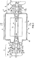
- A rotary graphite tube furnace and the manner in which it may be practiced is further illustrated with reference to the accompanying drawings wherein:
- Fig. 1
- shows a sectional side view of a graphite rotary tube furnace of the present invention;
- Fig. 2
- is a cross-sectional view of the graphite rotary tube furnace of the present invention taken along the reference line 2-2' of Fig. 1 and
- Fig. 3
- is a cross-sectional view of the heating section of the furnace of the present invention taken along the reference line 3-3'.
- In Fig. 1 a side sectional view of a graphite rotary tube furnace 1 of the present invention includes a
graphite tube 2 comprising anentrance zone 3, a heating zone 4 and aproduct discharge zone 5. It will be appreciated by those skilled in the art that, although the graphite rotary tube furnace of this invention is referred to an illustrated as substantially horizontal, it may, in practice, be tilted from the horizontal to aid in the movement of materials therethrough. In the embodiment depicted, thegraphite tube 2 is assembled from three sections joined by means of threadedjoints 6. However, in other embodiments, thegraphite tube 2 may be constructed as a single unit or of any multiplicity of sections, depending on various considerations, such as the total length required and variations in the treatment of product along the length, resulting in different replacement schedules for maintenance purposes. - Material, such as particulate material, to be treated may be introduced through material inlet 7 in
hood 10 at theentrance zone 3 and discharged atproduct discharge zone 5 through hood 8 and collected in a container (not shown) attached thereto. The heating section 4 comprises a heating chamber 11 withininsulation enclosure 9 which, in turn, may be enclosed in ametal shell 31 which may be of a suitably heat resistant material, such as stainless steel. The heating chamber 11 may contain one ore more electrical heating elements 12 (Fig. 3). Theinsulation enclosure 9 is a high temperature insulation, such as graphite or a suitable fibrous insulation such as carbon (or graphite) fiber insulation. In a preferred embodiment, thegraphite insulation 9 may be further encased in a water cooledouter shell 13 which may be made of a heat resistant material such as stainless steel. - The
graphite tube 2 is rotated by means of adrive plate 14 preferably of stainless steel. Thedrive plate 14 may be attached to thegraphite tube 2, indirectly through a keyed or splined orsimilar connection 15 to transmit rotational torque from a motor source (not shown) through the drive plate to the graphite tube, while allowing for differences in the thermal expansion. - The
graphite tube 2 is supported by splitgraphite ring bearings 16 at two or more positions along its length. In the preferred embodiment, as illustrated, the graphite bearings are mounted in split ring water-cooledjackets 17 to maintain the bearings at a lower temperature. In addition to providing a cool temperature for the graphite bearings, water-cooled jackets may be extended to provide cooling zones in various parts of the furnace. Thus, for example, in the embodiment depicted in Fig. 1, the split ring water-cooledjackets 17 are extended horizontally to provide additional cooling at the product discharge zone to bring the product to a desired lower temperature as it exists the furnace atproduct outlet 28. Furthermore, in the embodiment illustrated, agas inlet 21 andgas outlet 27 are provided to allow the passage of cooling gas therethrough between the graphite bearings to further aid in the cooling of the product as it passes through theproduct discharge zone 5 prior to exiting the furnace at product atproduct outlet 28. - In some embodiments it may be preferable to omit the water-cooled jackets over some graphite bearings. For example, in the case of longer graphite tube embodiments, where it may be necessary to provide additional support by placing additional graphite bearings within the heating chamber 11, it may be preferred to omit the water-cooled jackets around those bearings within the heating chamber. Also, if higher product discharge temperatures are desired, the water-cooled
jackets 17 around thegraphite bearings 16 in theproduct discharge end 5 may be made smaller or omitted. - In operation, at high temperatures, it is preferred to maintain a non-oxidizing atmosphere, such as nitrogen, argon, or the like, in the interior of the
graphite tube 2 as well as on the exterior to protect against oxidation of the graphite. The interior atmosphere may be controlled by passing a non-oxidizing gas, such as nitrogen, for example, in a counter-current direction, with the gas entering throughinlet port 25 in hood 8 in thedischarge zone 5 and existing throughoutlet port 26 inhood 10 in theentrance zone 3. If a co-current gas flow is desired,inlet port 25 andoutlet port 26 may be reversed in function so that gas flow is in the opposite direction. In addition,inlet port 25 andoutlet port 26 may also be used to pass selected reactive gases through the interior for specific treatments of the material passing through. - The outer surface of
graphite tube 2 may be protected against oxidation or other undesired chemical reactions with the graphite by maintaining a non-oxidizing atmosphere, such as an atmosphere of nitrogen, argon or the like in the space surrounding the graphite tube especially in the heating zone 4 where higher temperatures tend to intensify the problem. A positive pressure of gas may be maintained throughout the heating chamber 11 using gas inlet/outlet passageways graphite tube 2, when some eccentricity of motion may occur, an atmospheric seal is maintained with the aid of a flexible gas tight seal comprising graphite sealing rings 18 slidably pressed against either or both sides of thedrive plate 14 with one or moreflexible bellows 19, or other spring-loaded sealing assembly, to impart a positive sealing spring type force. The bellows 19, or other sealing assembly means, as well as thedrive plate 14 are preferably made of stainless steel to withstand the conditions of operation of the furnace. Preferably, agas inlet 29 is provided within graphite sealing rings 18 for the transmission of an inert gas, such as nitrogen, argon, or the like to maintain a positive pressure of the inert gas around thedrive plate 14 and the outside of thegraphite tube 2 in the region of theproduct entrance end 3 of the furnace. - The heating element(s) 12 mounted within the heating chamber 11 are preferably electrical heating elements and, most preferably graphite heating elements. They may be mounted vertically or horizontally or both. They may be powered and positioned as desired to provide a single constant temperature throughout the heating section 4 or to provide multiple temperature zones for thermal profiling.
- To prevent excessive radiation heat loss at the ends of the
graphite tube 2 there may be installed a multiplicity of semicircular radiation baffles 24 made of suitably heat resistant material, such as tantalum, zirconium, or the like, or preferably, graphite. Thebaffles 24 may be attached, for example by cementing, along the interior perimeter of thegraphite tube 2 to block direct radiation heat loss from the heating section 4 through the ends of thetube 2. - Although the invention has been described with reference to certain preferred embodiments, it will be appreciated by those skilled in the art that modifications and variations may be made without departing from the spirit and scope of the invention as defined by the appended claims.
-
- 1
- graphite rotary tube furnace
- 2
- graphite tube
- 3
- entrance zone or section
- 4
- heating zone or section
- 5
- discharge zone or end or section
- 6
- means of threaded point
- 7
- material inlet
- 8
- second hood
- 9
- insulation enclosure; graphite insulation
- 10
- first hood
- 11
- heating chamber
- 12
- (electrical) heating elements
- 13
- outer shell
- 14
- drive plate
- 15
- connection
- 16
- split graphitering bearings; graphite bearings
- 17
- jackets
- 18
- (graphite) sealing rings
- 19
- bellows or sealing assembly means
- 21
- gas inlet
- 24
- radiation baffles
- 25
- inlet port
- 26
- outlet port
- 27
- gas outlet
- 28
- product outlet
- 29
- gas inlet
- 31
- metall shell
- 32,33
- passageways
Claims (20)
- Rotary graphite tube furnace (1) for high temperature treatment of various materials in an inert atmosphere, characterized bya generally horizontally extending rotatable graphite tube (2) having a feed entrance zone (3), a heating zone (4), and a product discharge zone (5),a plurality of graphite bearings (16) slidably supporting said rotatable graphite tube (2),at least one of said split ring graphite bearings (16) being cooled by a water-cooled jacket (17),a drive plate (14) attached to said graphite tube (2) to transmit rotational torque thereto,an enclosure (9) around said graphite tube (2) adapted to maintain a selected atmosphere around and within said graphite tube (2), said enclosure (9) including two graphite sealing rings (18), each pressed against an opposite side of said drive plate (14) by a flexible atmospheric sealing assmbly (19) to maintain a slidable sealing relationship between said graphite sealing rings (18) and said drive plate (14),an insulated heating chamber (11) around said heating zone (4) containing one or more electrical heating elements (12) andgas inlet (29) and outlet (27) for the entry and exit of gas to supply a selected atmosphere to said insulation enclosure (9).
- Rotary graphite tube furnace according to claim 1, characterized in,that said graphite tube (2) has a multiplicity of radiation baffles (24) attached to an inner surface thereof to inhibit a loss of radiant heat at feed entrance end and product discharge end.
- Rotary graphite tube furnace according to claim 1, characterized in,that said graphite tube (2) comprises two or more tube sections.
- Rotary graphite tube furnace according to claim 3, charaterized in,that said tube sections are provided with threaded ends (6) for attachment and removal.
- Rotary graphite tube furnace according to claim 3, characterized in,that said graphite tube (2) comprises three removable and replaceable sections (3, 4, 5).
- Rotary graphite tube furnace according to claim 5, characterized in,that said tube sections (3 to 5) are provided with threaded ends (6) for attachment and removal.
- Rotary graphite tube furnace according to claim 2, characterized in,that said radiation baffles (24) are made of graphite.
- Rotary graphite tube furnace according to claim 1, characterized in,that said flexible atmospheric sealing assembly comprises at least one bellows (19) positioned concentrically around said graphite tube (2) and exerting a spring-like force against one of said graphite sealing rings (18) to maintain a slidable sealing relationship between said graphite sealing rings (18) and said drive plate (14).
- Rotary graphite tube furnace according to claim 8, charaterized in,that atmospheric sealing assembly means (19) comprises two of said bellows, each pressed against one of said graphite sealing rings (18) on opposite sides of said drive plate (14) to maintain a slidable sealing relationship between said graphite sealing rings (18) and said drive plate (14).
- Rotary tube furnace according to claim 9, characterized in,that the enclosure (9) around the graphite tube (2) comprises an assemblage of components including a first hood (10) at an end of said entrance zone (3) of the graphite tube (2), a second hood (8) at an end of said product discharge zone (5) of said graphite tube (2), one or more water cooled jackets (17), an insulated heating chamber (11) around said heating zone, said two graphite rings (18), said drive plate (14), said components being maintained in a sealing relationship by a spring-like force from said flexible atmospheric sealing assembly.
- Rotary tube furnace according to claim 10, charaterized in,that said insulated heating chamber (11) includes a gas inlet (21) and gas outlet (27) to allow the entry and exit of gas to maintain a selected atmosphere around the graphite tube (2) in said heating chamber (11).
- Rotary tube furnace according to claim 11, characterized in,that said heating chamber (11) contains a multiplicity of heating elements (12) capable of providing a multiplicity of temperature zones within the heating zone (4).
- Rotary tube furnace according to claims 10 characterized in,that said first hood (10) and said second hood (8) each include a gas port (25, 26) for the entry or exit of gas to provide a co-current or counter-current flow of gas through the graphite tube (2).
- Rotary tube furnace according to claim 3, characterized in,that the graphite rings (18) each include a gas entryway (29) for the transmission and maintenance of a positive pressure of gas against the drive plate (14).
- Rotary tube furnace according to claim 1, characterized in,that the product discharge zone (5) includes a cooling means.
- Rotary tube furnace according to claim 1, characterized in,that said graphite bearings are split ring graphite bearings (16).
- Rotary tube furnace according to claim 16, characterized in,that each of said split ring bearings (16) are surrounded by a split ring water cooled jacket (17).
- Rotary tube furnace (1), characterized bya generally horizontally extending rotatable graphite tube (2) comprising two or more removable and replaceable tube sections (3-5), said graphite tube (2) having a feed entrance zone (3), a heating zone (4), and a product discharge zone (5);by a multiplicity of graphite radiation baffles (24) attached to an inner surface of said graphite tube (2) to inhibit a loss of radiant heat;by a plurality of split ring graphite bearings (16) slidably supporting said rotatable graphite tube (2), at least one split ring bearing (16) being within the entrance zone (3) and at least one split ring bearing (16) being within said product discharge zone (5);by each of said split ring graphite bearings (16) within said entrance zone (3) and said product discharge zone (5), being surrounded by a water-cooled jacket (17);by a stainless-steel drive plate (14) attached to said graphite tube (2) to transmit rotational torque thereto, said drive plate (14) being attached to said graphite tube (2) by a keyway or spline connection to allow for differences in thermal expansion or contraction;by an enclosure (9) around said graphite tube (2) adapted to maintain a selected atmosphere around and within the graphite tube (2), the enclosure (9) comprising two graphite sealing rings (18), each pressed against an opposite side of said drive plate (14) by a flexible atmospheric sealing assembly to maintain a slidable sealing relationship between the graphite rings (18) and the drive plate (14), a first hood (10) at an end of the entrance zone (3) of the graphite tube (2), a second hood (8) at an end of the product discharge zone (5) of the graphite tube (2), at least two of said water-cooled jackets (17), an insulated heating chamber (11) around said heating zone (4), said two graphite rings (18), and said drive plate (14), said components being maintained in a sealing relationship by a spring-like force from said flexible atmospheric sealing assembly;by gas inlet (21) and outlet means (27) in the insulated heating chamber (11) for the entry and exit of gas to provide a selected atmosphere within said heating chamber (11);by a first gas port (25) in said first hood (10) and a second gas port (26) in said second hood (8) for the entry or exit of gas to provide a co-current or counter-current flow of gas through the graphite tube (2);by a gas inlet (21) within each of said graphite rings (18) for the transmission and maintenance of a positive pressure of gas against said drive plate (14).
- Rotary tube furnace according to claim 18, characterized in,that the graphite tube (2) comprises three removable and replaceable tube sections (3 to 5).
- Rotary tube furnace according to claim 18, characterized in,that the flexible atmospheric sealing assembly comprises two metal bellows (19), each providing a spring-like expansive force pressing in one direction against one of the graphite rings (18) on opposite sides of the drive plate (14) to maintain a slidable sealing relationship between the graphite rings (18) and the drive plate (14) and in an opposite direction against another of the components of the enclosure (9).
Applications Claiming Priority (2)
| Application Number | Priority Date | Filing Date | Title |
|---|---|---|---|
| US09/378,590 US6042370A (en) | 1999-08-20 | 1999-08-20 | Graphite rotary tube furnace |
| US378590 | 1999-08-20 |
Publications (1)
| Publication Number | Publication Date |
|---|---|
| EP1079190A1 true EP1079190A1 (en) | 2001-02-28 |
Family
ID=23493738
Family Applications (1)
| Application Number | Title | Priority Date | Filing Date |
|---|---|---|---|
| EP00115364A Withdrawn EP1079190A1 (en) | 1999-08-20 | 2000-07-15 | Graphite rotary tube furnace |
Country Status (4)
| Country | Link |
|---|---|
| US (1) | US6042370A (en) |
| EP (1) | EP1079190A1 (en) |
| JP (1) | JP2001082880A (en) |
| CN (1) | CN1285496A (en) |
Cited By (2)
| Publication number | Priority date | Publication date | Assignee | Title |
|---|---|---|---|---|
| FR2955175A1 (en) * | 2010-01-14 | 2011-07-15 | Inst Francais Du Petrole | Furnace for roasting biomass load to produce e.g. biofuels, has extraction unit extracting gas, another extraction unit extracting roasted biomass, and biomass load introducing unit introducing biomass load into cylindrical turning element |
| CN109110754A (en) * | 2018-10-11 | 2019-01-01 | 大同新成新材料股份有限公司 | A kind of graphitizing furnace and method for graphitizing |
Families Citing this family (39)
| Publication number | Priority date | Publication date | Assignee | Title |
|---|---|---|---|---|
| US6380517B2 (en) * | 1999-06-21 | 2002-04-30 | Cabot Corporation | High temperature rotating vacuum kiln and method for heat treating solid particulate material under a vacuum |
| US8211356B1 (en) | 2000-07-18 | 2012-07-03 | Surmet Corporation | Method of making aluminum oxynitride |
| DE20019276U1 (en) * | 2000-11-13 | 2002-03-28 | VEBA OEL Technologie und Automatisierung GmbH, 45879 Gelsenkirchen | Rotary drum with rolling element arrangement |
| NO20010929D0 (en) * | 2001-02-23 | 2001-02-23 | Norsk Hydro As | A method for conducting thermal reactions between reactants and an oven for the same |
| US6626976B2 (en) * | 2001-11-06 | 2003-09-30 | Cyprus Amax Minerals Company | Method for producing molybdenum metal |
| US6746656B2 (en) | 2001-11-07 | 2004-06-08 | Cyprus Amax Minerals Company | Methods for production of molybdenum carbide |
| SE0203844L (en) * | 2002-12-23 | 2003-10-14 | Sandvik Ab | Method and apparatus for transmitting electric current to an oven |
| DE20302000U1 (en) * | 2003-02-08 | 2004-07-08 | Vta Verfahrenstechnik Und Automatisierung Gmbh | Ring sealing arrangement for an indirectly heated rotary kiln |
| US6749425B1 (en) * | 2003-03-26 | 2004-06-15 | Jp Steel Plantech Co. | Indirect heating furnace |
| US7276102B2 (en) * | 2004-10-21 | 2007-10-02 | Climax Engineered Materials, Llc | Molybdenum metal powder and production thereof |
| WO2009139830A2 (en) * | 2008-05-13 | 2009-11-19 | Harper International Corporation | Overhung rotary tube furnace |
| US8088328B2 (en) * | 2008-06-13 | 2012-01-03 | Jones William R | Vacuum nitriding furnace |
| US20100178627A1 (en) * | 2009-01-09 | 2010-07-15 | Harper International Corporation | Automatic feed oven |
| JP5695348B2 (en) * | 2009-09-14 | 2015-04-01 | 高砂工業株式会社 | Rotary kiln |
| JP5592624B2 (en) * | 2009-09-14 | 2014-09-17 | 高砂工業株式会社 | Rotary kiln |
| CN102510988B (en) * | 2009-10-29 | 2014-07-09 | 月岛机械株式会社 | Rotary heat treatment apparatus |
| US9080813B1 (en) | 2010-04-12 | 2015-07-14 | George J. Deckebach | Adjusting rotational speeds of rotary kilns to increase solid/gas interaction |
| CN101891199B (en) * | 2010-07-08 | 2012-02-29 | 济南伟得热工材料有限公司 | Method for Preventing Damage of Graphite Tube Heater in Hydrogenation Furnace and Protective Cover Used |
| CN102889782B (en) * | 2012-09-03 | 2014-12-17 | 杭州金马能源科技有限公司 | Quartz tube type uniform roasting furnace |
| CN102937377B (en) * | 2012-09-03 | 2014-11-26 | 杭州金马能源科技有限公司 | High temperature resistant borosilicate hard glass and metal material encapsulated joint and manufacturing method thereof |
| EP2735544B1 (en) * | 2012-11-27 | 2020-09-30 | Ulusal Bor Arastirma Enstitusu (Boren) | A reactor designed for chemical vapor deposition method and method of producing elemental boron and advanced ceramic powders with this reactor |
| CN104121774B (en) * | 2013-04-24 | 2017-04-05 | 日本碍子株式会社 | Heat treatment method and annealing device |
| JP5752212B2 (en) * | 2013-11-13 | 2015-07-22 | 三菱重工環境・化学エンジニアリング株式会社 | Externally heated carbonization furnace |
| US9284210B2 (en) | 2014-03-31 | 2016-03-15 | Corning Incorporated | Methods and apparatus for material processing using dual source cyclonic plasma reactor |
| US9550694B2 (en) | 2014-03-31 | 2017-01-24 | Corning Incorporated | Methods and apparatus for material processing using plasma thermal source |
| US9533909B2 (en) | 2014-03-31 | 2017-01-03 | Corning Incorporated | Methods and apparatus for material processing using atmospheric thermal plasma reactor |
| KR101630945B1 (en) * | 2014-10-15 | 2016-06-16 | 주식회사 포스코 | Rotary kiln |
| US20160200618A1 (en) | 2015-01-08 | 2016-07-14 | Corning Incorporated | Method and apparatus for adding thermal energy to a glass melt |
| JP5778363B1 (en) * | 2015-01-21 | 2015-09-16 | Secカーボン株式会社 | Heat treatment equipment |
| CN105087889B (en) * | 2015-08-21 | 2017-07-07 | 哈尔滨工业大学(威海) | Heat treatment pipe type stove |
| KR101884459B1 (en) * | 2016-12-27 | 2018-08-01 | 한남대학교 산학협력단 | Rotary kiln and it's control method |
| JP7070104B2 (en) * | 2018-06-04 | 2022-05-18 | 住友電気工業株式会社 | Rotating furnace |
| CN108928813B (en) * | 2018-07-28 | 2021-04-02 | 尤官京 | A kind of graphene preparation tube furnace |
| CN110243180B (en) * | 2019-06-18 | 2020-01-17 | 中国科学院重庆绿色智能技术研究院 | A high temperature rotary tube furnace |
| CN112239204A (en) * | 2020-10-21 | 2021-01-19 | 宁夏墨工科技有限公司 | Microwave reactor for graphene preparation |
| CN116858756B (en) * | 2023-06-16 | 2025-04-04 | 西北工业大学 | A high temperature steam corrosion test device with adjustable atmosphere |
| CN117327873A (en) * | 2023-09-21 | 2024-01-02 | 中冶南方(武汉)热工有限公司 | Electric heating device for strip heat treatment furnace |
| CN117824351B (en) * | 2024-03-04 | 2024-05-03 | 佛山市天禄智能装备科技有限公司 | Pre-carbonization rotary kiln sealing system |
| CN119595689B (en) * | 2024-11-12 | 2025-11-04 | 中国航空工业集团公司沈阳飞机设计研究所 | A protective clamp for a graphite heater in an open environment and its usage method |
Citations (10)
| Publication number | Priority date | Publication date | Assignee | Title |
|---|---|---|---|---|
| DE699448C (en) * | 1938-02-03 | 1940-11-29 | Hermann Possekel | Device for the extraction of metals or metalloids |
| US3802847A (en) * | 1970-10-30 | 1974-04-09 | Sumitomo Electric Industries | Rotary furnace for carburization |
| US4193756A (en) * | 1978-03-08 | 1980-03-18 | Tosco Corporation | Seal assembly and method for providing a seal in a rotary kiln |
| GB2094906A (en) * | 1981-03-13 | 1982-09-22 | Tosco Corp | Retort seal mechanism |
| JPS6174635A (en) * | 1984-09-19 | 1986-04-16 | Nippon Cement Co Ltd | Continuous synthesizing apparatus of nonoxidizing material powder |
| EP0421411A2 (en) * | 1989-10-05 | 1991-04-10 | Knut Willi Weber | Rotary drum furnace |
| FR2680411A1 (en) * | 1991-08-14 | 1993-02-19 | Badey Jacques | Method and installation for recovering metals using fractionated fusion (melting) |
| WO1997014010A1 (en) * | 1995-10-06 | 1997-04-17 | Zinchem-Benelux - Ex Ets Franck & Steeman | Rotary furnace |
| WO1999067588A1 (en) * | 1998-06-22 | 1999-12-29 | Cabot Corporation | High temperature rotating vacuum kiln and method for heat treating solid particulate material under a vacuum |
| JP2000161859A (en) * | 1998-11-30 | 2000-06-16 | Daido Steel Co Ltd | Externally heated rotary kiln furnace and its operation control method |
Family Cites Families (5)
| Publication number | Priority date | Publication date | Assignee | Title |
|---|---|---|---|---|
| US4961391A (en) * | 1989-03-29 | 1990-10-09 | International Technology Corporation | Thermal treatment process for organically contaminated material |
| JP2960554B2 (en) * | 1990-12-27 | 1999-10-06 | 株式会社オーケー企画研究所 | Garbage disposal vehicle |
| AT398129B (en) * | 1991-01-14 | 1994-09-26 | Waagner Biro Ag | TURNTUBE HEAT TREATMENT SYSTEM, ESPECIALLY TURNTUBE TUBES |
| DK171152B1 (en) * | 1994-06-16 | 1996-07-01 | Smidth & Co As F L | Rotary drum suspended in running ring |
| FR2737554B1 (en) * | 1995-08-03 | 1997-08-29 | Commissariat Energie Atomique | ROTATING FUSION OVEN |
-
1999
- 1999-08-20 US US09/378,590 patent/US6042370A/en not_active Expired - Lifetime
-
2000
- 2000-07-06 CN CN00124269A patent/CN1285496A/en active Pending
- 2000-07-15 EP EP00115364A patent/EP1079190A1/en not_active Withdrawn
- 2000-08-02 JP JP2000234852A patent/JP2001082880A/en active Pending
Patent Citations (10)
| Publication number | Priority date | Publication date | Assignee | Title |
|---|---|---|---|---|
| DE699448C (en) * | 1938-02-03 | 1940-11-29 | Hermann Possekel | Device for the extraction of metals or metalloids |
| US3802847A (en) * | 1970-10-30 | 1974-04-09 | Sumitomo Electric Industries | Rotary furnace for carburization |
| US4193756A (en) * | 1978-03-08 | 1980-03-18 | Tosco Corporation | Seal assembly and method for providing a seal in a rotary kiln |
| GB2094906A (en) * | 1981-03-13 | 1982-09-22 | Tosco Corp | Retort seal mechanism |
| JPS6174635A (en) * | 1984-09-19 | 1986-04-16 | Nippon Cement Co Ltd | Continuous synthesizing apparatus of nonoxidizing material powder |
| EP0421411A2 (en) * | 1989-10-05 | 1991-04-10 | Knut Willi Weber | Rotary drum furnace |
| FR2680411A1 (en) * | 1991-08-14 | 1993-02-19 | Badey Jacques | Method and installation for recovering metals using fractionated fusion (melting) |
| WO1997014010A1 (en) * | 1995-10-06 | 1997-04-17 | Zinchem-Benelux - Ex Ets Franck & Steeman | Rotary furnace |
| WO1999067588A1 (en) * | 1998-06-22 | 1999-12-29 | Cabot Corporation | High temperature rotating vacuum kiln and method for heat treating solid particulate material under a vacuum |
| JP2000161859A (en) * | 1998-11-30 | 2000-06-16 | Daido Steel Co Ltd | Externally heated rotary kiln furnace and its operation control method |
Non-Patent Citations (2)
| Title |
|---|
| PATENT ABSTRACTS OF JAPAN vol. 10, no. 245 (C - 368)<2301> 22 September 1986 (1986-09-22) * |
| PATENT ABSTRACTS OF JAPAN vol. 2000, no. 09 13 October 2000 (2000-10-13) * |
Cited By (2)
| Publication number | Priority date | Publication date | Assignee | Title |
|---|---|---|---|---|
| FR2955175A1 (en) * | 2010-01-14 | 2011-07-15 | Inst Francais Du Petrole | Furnace for roasting biomass load to produce e.g. biofuels, has extraction unit extracting gas, another extraction unit extracting roasted biomass, and biomass load introducing unit introducing biomass load into cylindrical turning element |
| CN109110754A (en) * | 2018-10-11 | 2019-01-01 | 大同新成新材料股份有限公司 | A kind of graphitizing furnace and method for graphitizing |
Also Published As
| Publication number | Publication date |
|---|---|
| US6042370A (en) | 2000-03-28 |
| CN1285496A (en) | 2001-02-28 |
| JP2001082880A (en) | 2001-03-30 |
Similar Documents
| Publication | Publication Date | Title |
|---|---|---|
| US6042370A (en) | Graphite rotary tube furnace | |
| US4443186A (en) | Solar heated rotary kiln | |
| RU2301727C2 (en) | Vacuum furnace for pressure soldering and method for using it | |
| US7011510B2 (en) | Hot isostatic pressing apparatus and hot isostatic pressing method | |
| KR101597267B1 (en) | Overhung rotary tube furnace | |
| US5779468A (en) | Device for supplying gas to rotary kilns | |
| US5362230A (en) | Rolls for high temperature roller hearth furnaces | |
| US4256453A (en) | Calciner screw construction | |
| EP3891453B1 (en) | Expansion constraint assembly and related method | |
| US5393225A (en) | Rotating tube heat treatment installation, in particular rotating tubular kiln, with indirect heat feed or dissipation | |
| CA1326357C (en) | Rotary kiln | |
| US4629867A (en) | Heated rotatable roll arrangement | |
| US4543061A (en) | Air cooled rotary kiln feed end dam | |
| EP0549678A1 (en) | Method and device for cooling a rotary kiln. | |
| US6471509B2 (en) | Strip guiding device comprising a rotatable construction for changing supporting rolls having cooling means | |
| US3422205A (en) | Electric furnace having replaceable liner tube sections | |
| US3105863A (en) | Heat treating apparatus | |
| US5096415A (en) | Reaction furnace | |
| US7611663B2 (en) | Industrial furnace and associated jet element | |
| US4281963A (en) | Apparatus for the conveyance and/or treatment of hot gases | |
| EP1224337B1 (en) | Apparatus for supporting material to be treated in continuously operated thermal treatment furnaces | |
| RU633U1 (en) | Material firing plant | |
| AU2002312891A1 (en) | Rabble arm for a furnace | |
| SU1712759A1 (en) | Furnace roller | |
| SU913012A1 (en) | ELECTRIC OVEN 1 |
Legal Events
| Date | Code | Title | Description |
|---|---|---|---|
| PUAI | Public reference made under article 153(3) epc to a published international application that has entered the european phase |
Free format text: ORIGINAL CODE: 0009012 |
|
| 17P | Request for examination filed |
Effective date: 20000724 |
|
| AK | Designated contracting states |
Kind code of ref document: A1 Designated state(s): AT BE CH CY DE DK ES FI FR GB GR IE IT LI LU MC NL PT SE |
|
| AX | Request for extension of the european patent |
Free format text: AL;LT;LV;MK;RO;SI |
|
| AKX | Designation fees paid |
Free format text: AT BE CH CY DE DK ES FI FR GB GR IE IT LI LU MC NL PT SE |
|
| GRAP | Despatch of communication of intention to grant a patent |
Free format text: ORIGINAL CODE: EPIDOSNIGR1 |
|
| RIN1 | Information on inventor provided before grant (corrected) |
Inventor name: WEIDE, CARL VANDER |
|
| STAA | Information on the status of an ep patent application or granted ep patent |
Free format text: STATUS: THE APPLICATION IS DEEMED TO BE WITHDRAWN |
|
| 18D | Application deemed to be withdrawn |
Effective date: 20040706 |