EP1079165A1 - Compression fitting - Google Patents
Compression fitting Download PDFInfo
- Publication number
- EP1079165A1 EP1079165A1 EP00117508A EP00117508A EP1079165A1 EP 1079165 A1 EP1079165 A1 EP 1079165A1 EP 00117508 A EP00117508 A EP 00117508A EP 00117508 A EP00117508 A EP 00117508A EP 1079165 A1 EP1079165 A1 EP 1079165A1
- Authority
- EP
- European Patent Office
- Prior art keywords
- tube
- ferrule
- bead
- pilot portion
- free end
- Prior art date
- Legal status (The legal status is an assumption and is not a legal conclusion. Google has not performed a legal analysis and makes no representation as to the accuracy of the status listed.)
- Granted
Links
Images

Classifications
-
- F—MECHANICAL ENGINEERING; LIGHTING; HEATING; WEAPONS; BLASTING
- F16—ENGINEERING ELEMENTS AND UNITS; GENERAL MEASURES FOR PRODUCING AND MAINTAINING EFFECTIVE FUNCTIONING OF MACHINES OR INSTALLATIONS; THERMAL INSULATION IN GENERAL
- F16L—PIPES; JOINTS OR FITTINGS FOR PIPES; SUPPORTS FOR PIPES, CABLES OR PROTECTIVE TUBING; MEANS FOR THERMAL INSULATION IN GENERAL
- F16L33/00—Arrangements for connecting hoses to rigid members; Rigid hose connectors, i.e. single members engaging both hoses
- F16L33/20—Undivided rings, sleeves or like members contracted on the hose or expanded in the hose by means of tools; Arrangements using such members
- F16L33/207—Undivided rings, sleeves or like members contracted on the hose or expanded in the hose by means of tools; Arrangements using such members only a sleeve being contracted on the hose
- F16L33/2071—Undivided rings, sleeves or like members contracted on the hose or expanded in the hose by means of tools; Arrangements using such members only a sleeve being contracted on the hose the sleeve being a separate connecting member
- F16L33/2073—Undivided rings, sleeves or like members contracted on the hose or expanded in the hose by means of tools; Arrangements using such members only a sleeve being contracted on the hose the sleeve being a separate connecting member directly connected to the rigid member
Definitions
- This invention relates to fluid joints and more particularly to fluid joints utilizing a crimped ferrule to facilitate the formation of the joint.
- This invention is directed to the provision of an improved fluid joint; More particularly, this invention is directed to discouraging corrosion in a fluid joint of the type employing dissimilar metallic members.
- the joint further includes an elastomeric ring positioned in surrounding relation to the tube pilot portion between the bead and the second end of the ferrule.
- the elastomeric ring provides a seal between the ferrule and the bead to keep out contaminants such as water, salt, or dirt that may promote corrosion at the interface between the ferrule and the bead.
- the ring further provides isolation between the ferrule and the bead.
- the invention further provides a method of providing a fluid joint between a generally rigid metallic tube and a generally flexible hose.
- an annular bead is provided on the tube spaced from a free end of the tube to define a pilot portion between the bead and the tube free end; a metallic ferrule is provided having first and second ends; the first end of the ferrule is crimped over the free end of the hose; an elastomeric ring is provided; the ring is positioned in surrounding relation to the tube pilot portion; the tube pilot portion is inserted into the second end of the ferrule and into the free end of the hose to press the ring against the bead; and the second end of the ferrule is crimped to the tube pilot portion proximate the bead to trap the ring between the second end of the ferrule and the bead.
- This simple methodology provides a joint in which contamination or corrosion is discouraged at the interface of the ferrule and the bead.
- the fluid joint of the invention is useful in any scenario where it is desired to form a fluid joint between a generally rigid metallic tube and a generally flexible hose.
- modern day motor vehicles typically employ such a joint at each location where it is desired to establish a fluid tight joint between a relatively rigid metallic tube member and a relatively flexible hose member.
- the fluid joint of the invention includes a tube 10, a hose 12, a ferrule 14, and a ring 16.
- Hose 12 may be formed, for example, of a tough insoluble polymer such as Teflon® and may include a reinforced steel wire braid 18 encircling the hose.
- Hose 12 is generally flexible and has an inner diameter 12a approximating the outer diameter 10d of tube pilot portion 10c so that pilot portion 10c may be inserted into the free end 12b of the hose to provide a friction sealing interface between the outer diameter of the tube pilot portion and the inner diameter of the hose.
- Ferrule 14 has a tubular configuration and may be formed for example of stainless steel. Ferrule 14 has an inner diameter 14a approximating the outer diameter 12c of the hose and exceeding the outer diameter 10d of the tube pilot portion. Ferrule 14, in known manner, includes longitudinal creases 14b to facilitate crimping.
- Ring 16 is formed of an elastomeric material and may comprise what is commonly identified as an O-ring. Ring 16 has an inner diameter 16a approximating the outer diameter 10d of the tube pilot portion so that it may be readily slipped over the tube pilot portion.
- first ferrule end 14c is crimped at 20 over the free end 12b of hose 12; ring 16 is slipped over tube pilot portion 10c and into abutting engagement with the inboard face 10b of bead 10a; tube 10, carrying ring 16, is inserted into ferrule 14 and into tube 12 to insert the free end 10b of the tube pilot portion 10c into the free end 12b of the hose in sealing fashion and to position the second end 14d of the ferrule in abutting engagement with ring 16 (Fig. 4); and second ferrule end 14d is crimped at 22 against the outer diameter 10d of the tube pilot portion to trap the ring 16 between the inboard annular face 10b of the bead and the crimped ferrule end 14d.
- the invention will be seen to provide an improved fluid joint which is simple in construction and assembly and which operates to effectively preclude corrosion at the interface of dissimilar metals utilized in the formation of the joint.
Abstract
Description
- This invention relates to fluid joints and more particularly to fluid joints utilizing a crimped ferrule to facilitate the formation of the joint.
- It is often necessary, for example in the assembly of a motor vehicle to provide a fluid joint between a relatively rigid tube and a relatively flexible hose. It is common practice, for example, to form such a joint by the use of a ferrule coacting with an upset or bead formed on the tube at a location spaced from a free end of the tube to define a pilot portion between the bead and the tube free end for insertion into the free end of the hose. The joint is formed by inserting the pilot portion of the tube into the free end of the hose and crimping the ferrule at one end to the free end of the hose and at its other end to the pilot portion of the tube proximate the bead. Whereas this arrangement provides satisfactory fluid connection between the tube and the hose there is a tendency for galvanic action to occur between the dissimilar metallic materials of the ferrule and the tube at the interface of the ferrule and the bead with the result that corrosion may form at this location with consequent degradation of the joint.
- This invention is directed to the provision of an improved fluid joint; More particularly, this invention is directed to discouraging corrosion in a fluid joint of the type employing dissimilar metallic members.
- The invention concerns a fluid joint of the type including a generally rigid metallic tube having an annular bead spaced from a free end of the tube to define a pilot portion between the bead and the tube free end, a generally flexible hose sized to fit at a free end thereof over the tube pilot portion, and a metallic ferrule crimped at a first end thereof over the hose free end and crimped at a second end thereof over the tube pilot portion.
- According to the invention, the joint further includes an elastomeric ring positioned in surrounding relation to the tube pilot portion between the bead and the second end of the ferrule. The elastomeric ring provides a seal between the ferrule and the bead to keep out contaminants such as water, salt, or dirt that may promote corrosion at the interface between the ferrule and the bead. The ring further provides isolation between the ferrule and the bead.
- The invention further provides a method of providing a fluid joint between a generally rigid metallic tube and a generally flexible hose.
- According to the invention methodology, an annular bead is provided on the tube spaced from a free end of the tube to define a pilot portion between the bead and the tube free end; a metallic ferrule is provided having first and second ends; the first end of the ferrule is crimped over the free end of the hose; an elastomeric ring is provided; the ring is positioned in surrounding relation to the tube pilot portion; the tube pilot portion is inserted into the second end of the ferrule and into the free end of the hose to press the ring against the bead; and the second end of the ferrule is crimped to the tube pilot portion proximate the bead to trap the ring between the second end of the ferrule and the bead. This simple methodology provides a joint in which contamination or corrosion is discouraged at the interface of the ferrule and the bead.
- In the disclosed embodiment of the invention, the step of positioning the ring in surrounding relation to the pilot portion includes positioning the ring against the bead. Positioning the ring against the bead prior to insertion of the tube pilot portion into the second end of the ferrule insures proper positioning of the ring in the final configuration of the joint.
- Other objects, advantages and applications of the present invention will become apparent to those skilled in the art when the following description of the best mode contemplated for practicing the invention is read in conjunction with the accompanying drawings.
- The description herein makes reference to the accompanying drawings wherein like reference numerals refer to like parts throughout the several views, and wherein:
- Figure 1 is an assembled view of a fluid joint according to the invention;
- Figure 2 is an exploded view of the invention joint;
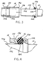
- Figure 3 is a view showing the assembly methodology of the joint; and
- Figure 4 is a detail view taken within the circle 4 of Figure 1.
-
- The fluid joint of the invention is useful in any scenario where it is desired to form a fluid joint between a generally rigid metallic tube and a generally flexible hose. For example, modern day motor vehicles typically employ such a joint at each location where it is desired to establish a fluid tight joint between a relatively rigid metallic tube member and a relatively flexible hose member.
- The fluid joint of the invention includes a
tube 10, ahose 12, aferrule 14, and aring 16. - Tube 10 may for example constitute a brake line tubing in a motor vehicle and may comprise a steel tube having an aluminum coating. An upset or
bead 10a is formed in the tube at a location spaced from thefree end 10b of the tube whereby to define a pilot tube portion 10c between the bead and the tube free end. -
Hose 12 may be formed, for example, of a tough insoluble polymer such as Teflon® and may include a reinforcedsteel wire braid 18 encircling the hose.Hose 12 is generally flexible and has aninner diameter 12a approximating the outer diameter 10d of tube pilot portion 10c so that pilot portion 10c may be inserted into the free end 12b of the hose to provide a friction sealing interface between the outer diameter of the tube pilot portion and the inner diameter of the hose. -
Ferrule 14 has a tubular configuration and may be formed for example of stainless steel.Ferrule 14 has an inner diameter 14a approximating the outer diameter 12c of the hose and exceeding the outer diameter 10d of the tube pilot portion.Ferrule 14, in known manner, includes longitudinal creases 14b to facilitate crimping. -
Ring 16 is formed of an elastomeric material and may comprise what is commonly identified as an O-ring.Ring 16 has an inner diameter 16a approximating the outer diameter 10d of the tube pilot portion so that it may be readily slipped over the tube pilot portion. - To assemble the invention joint (Fig 3.), first ferrule end 14c is crimped at 20 over the free end 12b of
hose 12;ring 16 is slipped over tube pilot portion 10c and into abutting engagement with theinboard face 10b ofbead 10a;tube 10, carryingring 16, is inserted intoferrule 14 and intotube 12 to insert thefree end 10b of the tube pilot portion 10c into the free end 12b of the hose in sealing fashion and to position thesecond end 14d of the ferrule in abutting engagement with ring 16 (Fig. 4); andsecond ferrule end 14d is crimped at 22 against the outer diameter 10d of the tube pilot portion to trap thering 16 between the inboardannular face 10b of the bead and the crimpedferrule end 14d. - In the assembled configuration of the joint,
ring 16 precludes the entry of contaminants such for example as water, salt, and dirt into the interface between the dissimilar metals of thetube 10 and theferrule 14 whereby to predude galvanic or battery action as between the dissimilar metals of the ferrule and the tube and thereby preclude corrosion. - The invention will be seen to provide an improved fluid joint which is simple in construction and assembly and which operates to effectively preclude corrosion at the interface of dissimilar metals utilized in the formation of the joint.
- Whereas a preferred embodiment of the invention has been illustrated and described in detail it will be apparent that various changes may be made in the disclosed embodiment without departing from the scope or spirit of the invention.
- While the invention has been described in connection with what is presently considered to be the most practical and preferred embodiment, it is to be understood that the invention is not to be limited to the disclosed embodiments but, on the contrary, is intended to cover various modifications and equivalent arrangements included within the spirit and scope of the appended claims, which scope is to be accorded the broadest interpretation so as to encompass all such modifications and equivalent structures as is permitted under the law.
Claims (7)
- A fluid joint comprising a generally rigid metallic tube (10) having an annular bead (10a) spaced from a free end (10b) of the tube to define a pilot portion (10c) between the bead and the tube free end, a generally flexible hose (12) sized to fit at a free end thereof over the pilot portion, and a metallic ferrule (14) crimped at a first end thereof over the hose free end and crimped at a second end thereof over the tube pilot portion, characterized in that:the joint further includes an elastomeric ring (16) positioned in surrounding relation to the tube pilot portion between the bead (10a) and the second end of the ferrule.
- A fluid joint according to claim 1 wherein the ferrule (14) and the tube (10) are formed of dissimilar metallic materials so that the elastomeric ring (16) acts to discourage galvanic action between the ferrule and the tube.
- A fluid joint comprising:a generally rigid metallic tube (10) having an annular bead (10a) spaced from a free end (10b) of the tube to define a pilot portion (10c)between the bead and the tube free end;a generally flexible hose (12) sized to fit at a free end thereof over the tube pilot portion;a metallic ferrule (14) crimped at a first end thereof over the hose free end and crimped at a second end thereof over the tube pilot portion; and an elastomeric ring (16) positioned in surrounding relation to the tube pilot portion (10c) and held against the bead by the crimped second end of the ferrule.
- A fluid joint according to claim 3 wherein the ferrule (14) and the tube (10) are formed of dissimliar metallic materials so that the elastomeric ring (16) acts to discourage galvanic action between the ferrule and the tube.
- A method of providing a fluid joint between a generally rigid metallic tube (10) and a generally flexible hose (12) comprising:providing an annular bead (10a) on the tube spaced from a free end (10b) of the tube to define a pilot portion (10c) between the bead and the tube free end;providing a metallic ferrule (14) having first and second ends;crimping the first end of the ferrule over the free end of the hose;providing an elastomeric ring (16);positioning the ring (16) in surrounding relation to the tube pilot portion (10c);inserting the tube pilot portion into the second end of the ferrule and into the free end of the hose to press the ring against the bead; andcrimping the second end of the ferrule to the tube pilot portion proximate the bead to trap the ring between the second end of the ferrule and the bead.
- A method according to claim 5 wherein the step of positioning the ring in surrounding relation to the tube pilot portion comprises positioning the ring against the bead.
- A method according to claim 5 wherein the metallic material of the ferrule is dissimilar with respect to the metallic material of the tube and the elastomeric ring acts to discourage galvanic action between the bead and the ferrule.
Applications Claiming Priority (4)
| Application Number | Priority Date | Filing Date | Title |
|---|---|---|---|
| US475581 | 1995-06-07 | ||
| US15002599P | 1999-08-20 | 1999-08-20 | |
| US150025P | 1999-09-01 | ||
| US09/475,581 US6422609B1 (en) | 1999-08-20 | 1999-12-30 | Fluid joint |
Publications (2)
| Publication Number | Publication Date |
|---|---|
| EP1079165A1 true EP1079165A1 (en) | 2001-02-28 |
| EP1079165B1 EP1079165B1 (en) | 2004-11-10 |
Family
ID=26847256
Family Applications (1)
| Application Number | Title | Priority Date | Filing Date |
|---|---|---|---|
| EP00117508A Expired - Lifetime EP1079165B1 (en) | 1999-08-20 | 2000-08-12 | Compression fitting |
Country Status (4)
| Country | Link |
|---|---|
| US (1) | US6422609B1 (en) |
| EP (1) | EP1079165B1 (en) |
| JP (1) | JP3507418B2 (en) |
| DE (1) | DE60015673T2 (en) |
Citations (2)
| Publication number | Priority date | Publication date | Assignee | Title |
|---|---|---|---|---|
| EP0530404A1 (en) * | 1991-09-05 | 1993-03-10 | Hewing GmbH | Pipe coupling |
| DE9411779U1 (en) * | 1994-07-21 | 1994-10-27 | Cohnen Beteiligungs Gmbh & Co | Hose connection |
Family Cites Families (12)
| Publication number | Priority date | Publication date | Assignee | Title |
|---|---|---|---|---|
| US1592175A (en) | 1924-07-10 | 1926-07-13 | U G I Contracting Company | Electric insulation for metal pipes |
| US2465669A (en) | 1947-07-18 | 1949-03-29 | Thomas J Tudor | Insulated pipe-line union for electrolysis control |
| US2850299A (en) | 1953-09-22 | 1958-09-02 | Dresser Ind | Flexible insulating coupling for threaded pipe |
| US3930676A (en) | 1970-11-13 | 1976-01-06 | Parker-Hannifin Corporation | Hose coupling and joint |
| JPS5368421A (en) * | 1976-11-30 | 1978-06-17 | Hitachi Cable Ltd | Connecting part of plastic hose |
| US4538837A (en) | 1982-09-29 | 1985-09-03 | Cronk Allan D | Anti-corrosion pipe apparatus |
| DE3765054D1 (en) * | 1986-08-01 | 1990-10-25 | Gates Hydraulics Ltd | HOSE COUPLING. |
| US5127157A (en) * | 1989-02-06 | 1992-07-07 | Hans Oetiker | Method of fastening hose to nipple |
| US5553896A (en) * | 1995-02-15 | 1996-09-10 | Pilot Industries, Inc. | Electrically insulated fluid coupling assembly |
| US5622394A (en) * | 1995-03-15 | 1997-04-22 | Bundy Corporation | Corrosion-resistant joint |
| DE19520195A1 (en) * | 1995-06-01 | 1996-12-05 | Grohe Kg Hans | Sanitary hose, method and device for its manufacture |
| US6016842A (en) * | 1996-01-17 | 2000-01-25 | Titeflex Corporation | End fittings for metal hose assemblies and method of attachment |
-
1999
- 1999-12-30 US US09/475,581 patent/US6422609B1/en not_active Expired - Lifetime
-
2000
- 2000-08-12 DE DE60015673T patent/DE60015673T2/en not_active Expired - Lifetime
- 2000-08-12 EP EP00117508A patent/EP1079165B1/en not_active Expired - Lifetime
- 2000-08-16 JP JP2000246901A patent/JP3507418B2/en not_active Expired - Fee Related
Patent Citations (2)
| Publication number | Priority date | Publication date | Assignee | Title |
|---|---|---|---|---|
| EP0530404A1 (en) * | 1991-09-05 | 1993-03-10 | Hewing GmbH | Pipe coupling |
| DE9411779U1 (en) * | 1994-07-21 | 1994-10-27 | Cohnen Beteiligungs Gmbh & Co | Hose connection |
Also Published As
| Publication number | Publication date |
|---|---|
| DE60015673T2 (en) | 2005-10-06 |
| DE60015673D1 (en) | 2004-12-16 |
| US6422609B1 (en) | 2002-07-23 |
| EP1079165B1 (en) | 2004-11-10 |
| JP3507418B2 (en) | 2004-03-15 |
| JP2001090887A (en) | 2001-04-03 |
Similar Documents
| Publication | Publication Date | Title |
|---|---|---|
| US5275448A (en) | Quick connect tubing connector and method of assembly | |
| US9777875B2 (en) | Clam shell push-to-connect assembly | |
| US7249788B2 (en) | Connector assembly for male and female members | |
| US5498043A (en) | Hose fitting having ferrule anti-rotation ratchet teeth | |
| EP0663558B1 (en) | Quick connect tubing connector | |
| US4733890A (en) | Formed fluid coupling apparatus | |
| US7150478B2 (en) | Integrated seal for tube to hose connection | |
| US7503595B2 (en) | Fitting having low volume crevice | |
| US5195787A (en) | Quick connector with heavy-duty retainer | |
| US4932689A (en) | Hose fitting assembly | |
| JP5777267B2 (en) | Maintenance-free fluid fittings | |
| US6447020B1 (en) | High-pressure integral tube coupling arrangements | |
| US5350203A (en) | Quick connect tubing connector and method of assembly | |
| EP0937935A1 (en) | Tubular coupling | |
| US20070152442A1 (en) | Brazeless connector for fluid transfer assemblies | |
| US20040066039A1 (en) | Mechanical tube to fitting connection | |
| EP1602870A1 (en) | Tube to hose coupling | |
| US20200256490A1 (en) | Enhanced hose fitting and method of assembly | |
| US20070046026A1 (en) | Tube-to-tube connection | |
| EP0174070B1 (en) | Formed fluid coupling apparatus | |
| EP1079165B1 (en) | Compression fitting | |
| US5842726A (en) | Preformed transition pipe coupling | |
| WO2000070259A1 (en) | Device and method for coupling a rigid pipe to a flexible hose | |
| JPH04126091U (en) | Corrugated pipe with fittings | |
| JPS61206892A (en) | Joint fitting for hose |
Legal Events
| Date | Code | Title | Description |
|---|---|---|---|
| PUAI | Public reference made under article 153(3) epc to a published international application that has entered the european phase |
Free format text: ORIGINAL CODE: 0009012 |
|
| AK | Designated contracting states |
Kind code of ref document: A1 Designated state(s): DE FR GB |
|
| AX | Request for extension of the european patent |
Free format text: AL;LT;LV;MK;RO;SI |
|
| 17P | Request for examination filed |
Effective date: 20010828 |
|
| AKX | Designation fees paid |
Free format text: DE FR GB |
|
| 17Q | First examination report despatched |
Effective date: 20030213 |
|
| GRAP | Despatch of communication of intention to grant a patent |
Free format text: ORIGINAL CODE: EPIDOSNIGR1 |
|
| GRAS | Grant fee paid |
Free format text: ORIGINAL CODE: EPIDOSNIGR3 |
|
| GRAA | (expected) grant |
Free format text: ORIGINAL CODE: 0009210 |
|
| AK | Designated contracting states |
Kind code of ref document: B1 Designated state(s): DE FR GB |
|
| REG | Reference to a national code |
Ref country code: GB Ref legal event code: FG4D |
|
| REF | Corresponds to: |
Ref document number: 60015673 Country of ref document: DE Date of ref document: 20041216 Kind code of ref document: P |
|
| ET | Fr: translation filed | ||
| PLBE | No opposition filed within time limit |
Free format text: ORIGINAL CODE: 0009261 |
|
| STAA | Information on the status of an ep patent application or granted ep patent |
Free format text: STATUS: NO OPPOSITION FILED WITHIN TIME LIMIT |
|
| 26N | No opposition filed |
Effective date: 20050811 |
|
| REG | Reference to a national code |
Ref country code: FR Ref legal event code: PLFP Year of fee payment: 16 |
|
| REG | Reference to a national code |
Ref country code: FR Ref legal event code: PLFP Year of fee payment: 17 |
|
| REG | Reference to a national code |
Ref country code: FR Ref legal event code: PLFP Year of fee payment: 18 |
|
| REG | Reference to a national code |
Ref country code: FR Ref legal event code: PLFP Year of fee payment: 19 |
|
| PGFP | Annual fee paid to national office [announced via postgrant information from national office to epo] |
Ref country code: DE Payment date: 20190828 Year of fee payment: 20 Ref country code: FR Payment date: 20190826 Year of fee payment: 20 |
|
| PGFP | Annual fee paid to national office [announced via postgrant information from national office to epo] |
Ref country code: GB Payment date: 20190827 Year of fee payment: 20 |
|
| REG | Reference to a national code |
Ref country code: GB Ref legal event code: PE20 Expiry date: 20200811 |
|
| PG25 | Lapsed in a contracting state [announced via postgrant information from national office to epo] |
Ref country code: GB Free format text: LAPSE BECAUSE OF EXPIRATION OF PROTECTION Effective date: 20200811 |