EP1079093B1 - Support mechanism and linear actuator for a unison ring of a vectoriable axisymmetric nozzle - Google Patents
Support mechanism and linear actuator for a unison ring of a vectoriable axisymmetric nozzle Download PDFInfo
- Publication number
- EP1079093B1 EP1079093B1 EP00307004A EP00307004A EP1079093B1 EP 1079093 B1 EP1079093 B1 EP 1079093B1 EP 00307004 A EP00307004 A EP 00307004A EP 00307004 A EP00307004 A EP 00307004A EP 1079093 B1 EP1079093 B1 EP 1079093B1
- Authority
- EP
- European Patent Office
- Prior art keywords
- vectoring
- slider bar
- vectoring ring
- joint
- actuator
- Prior art date
- Legal status (The legal status is an assumption and is not a legal conclusion. Google has not performed a legal analysis and makes no representation as to the accuracy of the status listed.)
- Expired - Lifetime
Links
Images


Classifications
-
- F—MECHANICAL ENGINEERING; LIGHTING; HEATING; WEAPONS; BLASTING
- F02—COMBUSTION ENGINES; HOT-GAS OR COMBUSTION-PRODUCT ENGINE PLANTS
- F02K—JET-PROPULSION PLANTS
- F02K1/00—Plants characterised by the form or arrangement of the jet pipe or nozzle; Jet pipes or nozzles peculiar thereto
- F02K1/002—Plants characterised by the form or arrangement of the jet pipe or nozzle; Jet pipes or nozzles peculiar thereto with means to modify the direction of thrust vector
- F02K1/008—Plants characterised by the form or arrangement of the jet pipe or nozzle; Jet pipes or nozzles peculiar thereto with means to modify the direction of thrust vector in any rearward direction
-
- Y—GENERAL TAGGING OF NEW TECHNOLOGICAL DEVELOPMENTS; GENERAL TAGGING OF CROSS-SECTIONAL TECHNOLOGIES SPANNING OVER SEVERAL SECTIONS OF THE IPC; TECHNICAL SUBJECTS COVERED BY FORMER USPC CROSS-REFERENCE ART COLLECTIONS [XRACs] AND DIGESTS
- Y02—TECHNOLOGIES OR APPLICATIONS FOR MITIGATION OR ADAPTATION AGAINST CLIMATE CHANGE
- Y02T—CLIMATE CHANGE MITIGATION TECHNOLOGIES RELATED TO TRANSPORTATION
- Y02T50/00—Aeronautics or air transport
- Y02T50/60—Efficient propulsion technologies, e.g. for aircraft
Definitions
- This invention relates generally to axisymmetric variable throat thrust vectoring nozzles and, more particularly, to a linear actuation and vectoring ring support and actuation apparatus for the actuating and supporting vectoring ring that is used to pivot the nozzle flaps that vector the nozzle exhaust flow.
- U.S. Patent No. 4,994,660 issued to Hauer discloses an axisymmetric vectoring exhaust nozzle that provides a means for vectoring the thrust of an axisymmetric convergent/divergent nozzle by universally pivoting the divergent flaps of the nozzle in an asymmetric fashion or, in other words, pivoting the divergent flaps in radial and tangential directions with respect to the unvectored nozzle centerline.
- the flaps are pivoted by a vectoring ring which can be axially translated and gimballed or tilted about its horizontal and vertical axis (essentially have its attitude adjusted) through a limited range.
- Vectored thrust produces tangential and radial loads referred to as side loads that are transmitted from the flaps by various load paths back to the engine casing through the actuators. These tremendous loads require heavy actuators to absorb the loads and, particularly, the bending moments exerted on the actuator shafts by thrust vectoring.
- U.S. Patent No. 5,174,502 issued to Lippmeier et al, discloses a support for the vectoring ring that transfers at least a portion of the side loads acting generated by a gas turbine engine thrust vectoring nozzle to a relatively stationary portion of the engine.
- U.S. Patent No. 5,174,502 discloses an apparatus to minimize or eliminate the side loads transferred by the nozzle to the actuators, reduce or eliminate the bending moments that the actuators would be subject to due to the radial loads, and to minimize the size and weight of the nozzle actuators and hydraulic system used to power the actuators.
- the support includes pivotal links that provides for allowing two degree of freedom (2 DOF) pivoting or gimballing motion and axial translation of the vectoring ring.
- One of the embodiments has a dual link support means with a rectangular first link pivotally attached to the engine casing by a hinge.
- the first link is pivotally connected to a second link which in turn is universally hinged to the vectoring ring by a 3 DOF or spherical joint.
- a vectoring ring support and actuation apparatus for actuating a vectoring ring and transferring the side loads acting on the vectoring ring and generated by a gas turbine engine thrust vectoring nozzle to a relatively stationary portion of the engine and tilting the vectoring ring to vector the thrust of the nozzle.
- the vectoring ring support and actuation apparatus includes a linear actuator connected by a slider bar to the vectoring ring.
- a first actuator joint connects the linear actuator to a forward end of the slider bar and an aft actuator joint connecting an aft end of the slider bar to the vectoring ring.
- a vectoring ring support apparatus slidably supports the slider bar, restrains circumferential movement of the vectoring ring, and transfers side loads acting on the vectoring ring to a relatively stationary portion of the engine.
- the aft actuator joint preferably has three degrees of freedom and the forward actuator joint has one rotational degree of freedom.
- the aft actuator joint preferably is a ball joint having three rotational degrees of freedom.
- the forward actuator joint is preferably a clevis joint including two lugs interdigitated with and pivotably pinned to three lugs.
- the vectoring ring support apparatus includes at least one guide assembly having a hollow guide mounted on a casing of the engine by a support structure and the slider bar slidably supported within the guide.
- the vectoring ring support apparatus includes forward and aft ones of the support wherein the aft support is spaced apart from and aft of the forward support.
- Another embodiment includes rollers mounted to and inside of the hollow guide and disposed between the guide and the slider bar.
- Other embodiments provide the slider bar being hollow rectangular or cylindrical in cross-section.
- an annular liner bearing is slidably disposed about the cylindrical slider bar and is retained by radially running slots or tracks in the circumferential ring support assembly.
- linear actuation and vectoring ring support apparatus of the present invention is the combined ability to reduce or even eliminate the side loads transferred to the vectoring ring actuators and the bending moments that the actuators and their arms would be subjected to with the ability to actuate the vectoring ring.
- the present invention also reduces the overall size of the structure needed to perform both of these functions as compared to designs in the prior art and reduces the number of parts used to provide the combined functions of the invention.
- the present invention combines the actuation and support mechanisms for the vectoring ring rather than splitting up the functions of ring support and ring actuation into two separate interface points on the vectoring ring and accomplishes the two functions of ring actuation and support with a single mechanism making the apparatus less complicated and structurally improved over that of the prior art.
- the invention frees up space in the circumferential direction along the exhaust duct or engine casing, making it easier to find room for other nozzle hardware.
- the present invention eliminates a set of clevises on the vectoring ring which would be used to fasten the actuators to the ring, thus, simplifying the ring and reducing its cost and weight. Placing the vectoring ring actuators in front of and in line with the support and actuation apparatus of the present invention opens up space in the circumferential direction around the nozzle engine casing, making it easier to find room for other nozzle hardware.
- FIG. 1 The present invention is illustrated in FIG. 1 as a linear actuation and vectoring ring support apparatus 98 that includes a vectoring ring support apparatus 100 illustrated as part of an exhaust section 10 of an aircraft gas turbine engine comprising in serial flow relationship a fixed area exhaust duct or engine casing 11, including an afterburner liner 12, and a variable area downstream section 13 having an axisymmetric vectoring nozzle 14 of the convergent divergent type as referenced previously in the Hauer patent.
- a linear actuation and vectoring ring support apparatus 98 that includes a vectoring ring support apparatus 100 illustrated as part of an exhaust section 10 of an aircraft gas turbine engine comprising in serial flow relationship a fixed area exhaust duct or engine casing 11, including an afterburner liner 12, and a variable area downstream section 13 having an axisymmetric vectoring nozzle 14 of the convergent divergent type as referenced previously in the Hauer patent.
- nozzle 14 comprises in serial flow relationship a convergent section 34, a throat 40 and a divergent section 48.
- the convergent section 34 includes a plurality of convergent or primary flaps 50 circumferentially disposed about an engine centerline 8 with overlapping primary seals 51 disposed between and in sealing engagement with the radially inward facing surface of circumferentially adjacent primary flaps 50.
- Primary flap 50 is pivotally attached at its forward end to casing 11 by first pivotal or clevis joint 52.
- a divergent or secondary flap 54 is pivotally attached at its forward end 53 to the aft end of primary flap 50 by a universal two degree of freedom (2 DOF) joint such as a flap ball joint 56 generally at an axial position in the nozzle 14 which coincides with throat 40.
- Secondary flaps 54 are generally circumferentially disposed about engine centerline 8 with overlapping divergent or secondary seals 55 disposed between and in sealing engagement with the radially inward facing surface of circumferentially adjacent secondary flaps 54.
- Throat 40 has associated with it a throat area conventionally referred to as A8 and the nozzle exit 44 is generally at the end of secondary flaps 54 and has an exit area associated with it conventionally referred to as A9.
- a plurality of rollers 62 are disposed in a primary ring structure 66 which in turn is translated forward and aft by a plurality of primary actuators 70, of which there are three in the preferred embodiment. More than three primary actuators 70 may be used in conjunction with the present invention.
- the variable throat area A8 is controlled by the action of cam roller 62 on the cam surface 60 which is formed on the back of primary flap 50. During operation, the high pressure of the exhaust gases within the nozzle force primary flaps 50 and secondary flaps 54 radially outward, thus, keeping cam surface 60 in contact with cam roller 62.
- a conical annular actuator support 76 is mounted at its narrow forward end to engine casing 11 and primary actuator 70 is pivotally connected to the wide aft end of the conical actuator support 76 by a universal ball joint 74.
- Primary actuator 70 has an actuator rod 73 which in turn is connected to primary ring structure 66 by a spherical joint 68.
- a plurality of vectoring actuators 90 are equi-angularly disposed circumferentially around casing 11 and mounted to conical actuator support 76 by universal ball joints 94 in a similar manner as actuators 70.
- a vectoring ring 86 is used to control the positioning or pivoting of secondary flaps 54 to provide thrust vectoring.
- Secondary flaps 54 are pivotally connected to primary flaps 50 by the flap ball joint 56 and is pivotally controlled in a multi-degree of freedom manner by a plurality of respective Y-frames 59 having control arms 57 and 58 that operably connect vectoring ring 86 to secondary flap 54.
- Outer flaps 64 are at least partially supported by Y-frames 59 and provide a clean and smooth aerodynamic shape along the exterior of the nozzle.
- Control arms 57 and 58 are connected to vectoring ring 86 by 3 DOF spherical joints 82 and to the aft end of secondary flap 54 by a spherical joint 84.
- This linkage is operable to translate an attitude change of vectoring ring 86 into a multi-degree of freedom pivoting change or orbital movement of secondary flap 54 whereby each secondary flap may be pivoted through a different angle.
- Backbone 92 provides a mount for secondary flap 54 and support for joint 84 and flap ball joint 56 at its two ends.
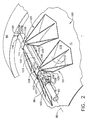
- FIGS. 2 and 3 more clearly illustrate how the vectoring ring 86 is supported and actuated by three of the vectoring ring support apparatuses 100.
- Each of the vectoring ring apparatuses 100 includes at least one and preferably two axially spaced apart forward and aft guide assemblies 101 and 104 respectively.
- Each guide assembly 104 has a support structure 106 with two circumferentially spaced apart legs 105 that support a hollow guide 108 within which is slidably disposed an axially translatable slider bar 102 having a bar axis 103.
- the legs 105 are reinforced by braces or gussets 113 attached to a base 115 of the guide assemblies 104 to provide additional strength and stability to the support structure 106.
- the guide 108 includes circumferentially spaced apart slider surfaces 112 on corresponding sides of the legs 105.
- the legs 105 are fixedly mounted on a relatively stationary portion of the engine such as the exhaust duct or engine casing 11.
- the vectoring ring support apparatus 100 provides a circumferential ring support means for slidably supporting the slider bar, restraining circumferential movement of the vectoring ring, and transferring side loads acting on the vectoring ring to a relatively stationary portion of the engine.
- Each of the vectoring actuators 90 includes a vectoring actuator rod 93 disposed about an actuator axis 95.
- a first aft end 91 of the vectoring actuator rod 93 is connected to a first forward end 107 of the slider bar 102 by a forward actuator joint 96 having a single rotational degree of freedom.
- the forward actuator joint 96 is preferably a clevis joint illustrated as having two lugs 126 on the first aft end 91 of the vectoring actuator rod 93 which are interdigitated with and pivotably pinned by a first pin 128 to three lugs 130 on the first forward end 107 of the slider bar 102.
- the first pin 128 has an axis that intersects and is perpendicular to the nozzle centerline or engine centerline 8.
- the clevis joint permits the actuator axis 95 to be out of alignment with the bar axis 103. This accommodates manufacturing and assembly tolerances between the actuator support 76 on the engine casing 11 and the support structure 106.
- the pinned forward actuator joint 96 also keeps the actuator rod 93 and the slider bar 102 in alignment in a radial plane through the nozzle or engine centerline 8, thus, preventing them from buckling relative to each other.
- the vectoring ring 86 is connected to a second aft end 116 of the slider bar 102 by a second joint 120 which is a universal joint and, preferably, a ball joint having three rotational degrees of freedom.
- the linear actuation and vectoring ring support apparatuses 98 provides for the vectoring ring 86 to be axially translated and tilted about centerline 8 in order to control its attitude.
- the three vectoring actuators 90 and the corresponding three linear actuation and vectoring ring support apparatuses 100 are equi-angularly disposed circumferentially about casing 11, that allows vectoring ring 86 to be axially translated and gimballed by the vectoring actuators 90.
- the slider bar 102, the forward actuator joint 96, and the second joint 120 allows the actuator 90 to both tilt and translate the vectoring ring 86 by simultaneously or differentially extending the three actuators 90.
- the guide assembly 104 eliminates the transfer of side loads acting in a direction tangential to the engine casing 11 that may otherwise be imparted to the actuator.
- the guide assembly 104 allows the slider bar 102 to absorb circumferential loads from vectoring ring 86 and transfer it to the engine casing 11 so that the three vectoring ring support apparatuses 100 act together to prevent sideways movement of the vectoring ring.
- the vectoring ring support apparatuses 100 allow attitude adjustment or gimballing and translating of the vectoring ring 86 and also permit axial translation of the vectoring ring to provide control of exit area A9.
- the slider bar 102 illustrated in FIG. 2 has a solid rectangular cross-section RX as illustrated in FIG. 7 and slides along the slider surfaces 112 inside the hollow guide 108.
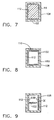
- the slider bar 102 preferably has a hollow rectangular cross-section HRX as illustrated in FIG. 8 and acts as a hollow box beam 110.
- the slider bar 102 has I beam cross-section IX with flanges 230 of the I contacting the slider surfaces 112.
- FIG. 3 An alternative embodiment of the hollow guide 108 is illustrated in FIG. 3, in which the slider surfaces 112 are replaced with rollers 118 which engage the slider bar 102, thus, allowing the slider bar to slide through the guide very easily.
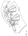
- FIGS. 4 and 5 Another alternative embodiment of the hollow guide 108 is illustrated in FIGS. 4 and 5 in which the slider bar is a cylindrical slider bar 202 having a circular cross-section.
- the cylindrical slider bar 202 is slidably disposed within an annular linear motion bearing 204 on each of the guide assemblies 104.
- the annular linear motion bearing 204 is retained in radially running tracks 206 in the circumferentially spaced apart legs 105 of the of the guide assembly 104.
- the linear motion bearing 204 in FIG. 5 is illustrated as a journal bearing with a low friction contact surface between the cylindrical slider bar 202 and the linear motion bearing.
- the tracks 206 are illustrated as grooves cut in legs 105.
- the annular linear motion bearing 204 can roll in the track 206 and translate radially during vectoring of the nozzle.
- FIG. 6 illustrates an alternative embodiment of the linear motion bearing 204 having recirculating ball bearings 220 between it and the cylindrical slider bar 202.
Description
- This invention relates generally to axisymmetric variable throat thrust vectoring nozzles and, more particularly, to a linear actuation and vectoring ring support and actuation apparatus for the actuating and supporting vectoring ring that is used to pivot the nozzle flaps that vector the nozzle exhaust flow.
- For military aircraft applications, there exists a need to increase the maneuverability of the aircraft, both for air to air combat missions and complicated ground attack missions. Aircraft designers seek to replace or augment the use of conventional aerodynamic surfaces such as flaps and ailerons with vectorable nozzles which turn or vector the exhaust flow and thrust of the gas turbine engine powering the aircraft. U.S. Patent No. 4,994,660, issued to Hauer discloses an axisymmetric vectoring exhaust nozzle that provides a means for vectoring the thrust of an axisymmetric convergent/divergent nozzle by universally pivoting the divergent flaps of the nozzle in an asymmetric fashion or, in other words, pivoting the divergent flaps in radial and tangential directions with respect to the unvectored nozzle centerline. The flaps are pivoted by a vectoring ring which can be axially translated and gimballed or tilted about its horizontal and vertical axis (essentially have its attitude adjusted) through a limited range.
- Vectored thrust produces tangential and radial loads referred to as side loads that are transmitted from the flaps by various load paths back to the engine casing through the actuators. These tremendous loads require heavy actuators to absorb the loads and, particularly, the bending moments exerted on the actuator shafts by thrust vectoring.
- U.S. Patent No. 5,174,502, issued to Lippmeier et al, discloses a support for the vectoring ring that transfers at least a portion of the side loads acting generated by a gas turbine engine thrust vectoring nozzle to a relatively stationary portion of the engine. U.S. Patent No. 5,174,502 discloses an apparatus to minimize or eliminate the side loads transferred by the nozzle to the actuators, reduce or eliminate the bending moments that the actuators would be subject to due to the radial loads, and to minimize the size and weight of the nozzle actuators and hydraulic system used to power the actuators. The support includes pivotal links that provides for allowing two degree of freedom (2 DOF) pivoting or gimballing motion and axial translation of the vectoring ring. One of the embodiments has a dual link support means with a rectangular first link pivotally attached to the engine casing by a hinge. The first link is pivotally connected to a second link which in turn is universally hinged to the vectoring ring by a 3 DOF or spherical joint.
- Briefly, in accordance with one aspect of the present invention, a vectoring ring support and actuation apparatus is provided for actuating a vectoring ring and transferring the side loads acting on the vectoring ring and generated by a gas turbine engine thrust vectoring nozzle to a relatively stationary portion of the engine and tilting the vectoring ring to vector the thrust of the nozzle. The vectoring ring support and actuation apparatus includes a linear actuator connected by a slider bar to the vectoring ring. A first actuator joint connects the linear actuator to a forward end of the slider bar and an aft actuator joint connecting an aft end of the slider bar to the vectoring ring. A vectoring ring support apparatus slidably supports the slider bar, restrains circumferential movement of the vectoring ring, and transfers side loads acting on the vectoring ring to a relatively stationary portion of the engine.
- The aft actuator joint preferably has three degrees of freedom and the forward actuator joint has one rotational degree of freedom. The aft actuator joint preferably is a ball joint having three rotational degrees of freedom. The forward actuator joint is preferably a clevis joint including two lugs interdigitated with and pivotably pinned to three lugs.
- In one embodiment of the present invention, the vectoring ring support apparatus includes at least one guide assembly having a hollow guide mounted on a casing of the engine by a support structure and the slider bar slidably supported within the guide. Preferably, the vectoring ring support apparatus includes forward and aft ones of the support wherein the aft support is spaced apart from and aft of the forward support. Another embodiment includes rollers mounted to and inside of the hollow guide and disposed between the guide and the slider bar. Other embodiments provide the slider bar being hollow rectangular or cylindrical in cross-section. In the cylindrical embodiment, an annular liner bearing is slidably disposed about the cylindrical slider bar and is retained by radially running slots or tracks in the circumferential ring support assembly.
- Among the advantages provided by the linear actuation and vectoring ring support apparatus of the present invention is the combined ability to reduce or even eliminate the side loads transferred to the vectoring ring actuators and the bending moments that the actuators and their arms would be subjected to with the ability to actuate the vectoring ring. The present invention also reduces the overall size of the structure needed to perform both of these functions as compared to designs in the prior art and reduces the number of parts used to provide the combined functions of the invention. The present invention combines the actuation and support mechanisms for the vectoring ring rather than splitting up the functions of ring support and ring actuation into two separate interface points on the vectoring ring and accomplishes the two functions of ring actuation and support with a single mechanism making the apparatus less complicated and structurally improved over that of the prior art. The invention frees up space in the circumferential direction along the exhaust duct or engine casing, making it easier to find room for other nozzle hardware.
- The present invention eliminates a set of clevises on the vectoring ring which would be used to fasten the actuators to the ring, thus, simplifying the ring and reducing its cost and weight. Placing the vectoring ring actuators in front of and in line with the support and actuation apparatus of the present invention opens up space in the circumferential direction around the nozzle engine casing, making it easier to find room for other nozzle hardware.
- The invention will now be described in greater detail, by way of example, with reference to the drawings, in which:-
- FIG. 1 is a partial cut-away perspective view illustration of a gas turbine engine axisymmetric vectoring exhaust nozzle with a linear actuation and vectoring ring support apparatus in accordance with the preferred embodiment of the present invention.
- FIG. 2 is an enlarged view of the preferred embodiment of the linear actuation and vectoring ring support apparatus illustrated in FIG. 1.
- FIG. 3 is a perspective view illustration of a first alternative embodiment of linear actuation and vectoring ring support apparatus illustrated in FIG. 1.
- FIG. 4 is a perspective view illustration of a second alternative embodiment of linear actuation and vectoring ring support apparatus illustrated in FIG. 1.
- FIG. 5 is a cross-sectional schematic illustration of a cylindrical slider bar mounted within a linear motion bearing in the linear actuation and vectoring ring support apparatus illustrated in FIG. 4.
- FIG. 6 is a cross-sectional schematic illustration of a cylindrical slider bar mounted within a linear motion bearing having recirculating ball bearings in the linear actuation and vectoring ring support apparatus illustrated in FIG. 4.
- FIG. 7 is a cross-sectional schematic illustration of the slider bar with a rectangular cross-section.
- FIG. 8 is a cross-sectional schematic illustration of a hollow slider bar with a hollow rectangular cross-section.
- FIG. 9 is a cross-sectional schematic illustration of an I beam slider bar with an I beam cross-section.
- The present invention is illustrated in FIG. 1 as a linear actuation and vectoring
ring support apparatus 98 that includes a vectoringring support apparatus 100 illustrated as part of anexhaust section 10 of an aircraft gas turbine engine comprising in serial flow relationship a fixed area exhaust duct orengine casing 11, including anafterburner liner 12, and a variable areadownstream section 13 having anaxisymmetric vectoring nozzle 14 of the convergent divergent type as referenced previously in the Hauer patent. - Referring to FIG. 1,
nozzle 14 comprises in serial flow relationship aconvergent section 34, athroat 40 and adivergent section 48. Theconvergent section 34 includes a plurality of convergent orprimary flaps 50 circumferentially disposed about anengine centerline 8 with overlappingprimary seals 51 disposed between and in sealing engagement with the radially inward facing surface of circumferentially adjacentprimary flaps 50.Primary flap 50 is pivotally attached at its forward end tocasing 11 by first pivotal orclevis joint 52. A divergent orsecondary flap 54 is pivotally attached at itsforward end 53 to the aft end ofprimary flap 50 by a universal two degree of freedom (2 DOF) joint such as aflap ball joint 56 generally at an axial position in thenozzle 14 which coincides withthroat 40.Secondary flaps 54 are generally circumferentially disposed aboutengine centerline 8 with overlapping divergent orsecondary seals 55 disposed between and in sealing engagement with the radially inward facing surface of circumferentially adjacentsecondary flaps 54.Throat 40 has associated with it a throat area conventionally referred to as A8 and thenozzle exit 44 is generally at the end ofsecondary flaps 54 and has an exit area associated with it conventionally referred to as A9. - A plurality of
rollers 62 are disposed in aprimary ring structure 66 which in turn is translated forward and aft by a plurality ofprimary actuators 70, of which there are three in the preferred embodiment. More than threeprimary actuators 70 may be used in conjunction with the present invention. The variable throat area A8 is controlled by the action ofcam roller 62 on thecam surface 60 which is formed on the back ofprimary flap 50. During operation, the high pressure of the exhaust gases within the nozzle forceprimary flaps 50 andsecondary flaps 54 radially outward, thus, keepingcam surface 60 in contact withcam roller 62. A conicalannular actuator support 76 is mounted at its narrow forward end toengine casing 11 andprimary actuator 70 is pivotally connected to the wide aft end of theconical actuator support 76 by auniversal ball joint 74.Primary actuator 70 has anactuator rod 73 which in turn is connected toprimary ring structure 66 by aspherical joint 68. - A plurality of
vectoring actuators 90, of which there are three in the preferred embodiment, are equi-angularly disposed circumferentially aroundcasing 11 and mounted toconical actuator support 76 byuniversal ball joints 94 in a similar manner asactuators 70. - A
vectoring ring 86 is used to control the positioning or pivoting ofsecondary flaps 54 to provide thrust vectoring.Secondary flaps 54 are pivotally connected toprimary flaps 50 by theflap ball joint 56 and is pivotally controlled in a multi-degree of freedom manner by a plurality of respective Y-frames 59 havingcontrol arms ring 86 tosecondary flap 54.Outer flaps 64 are at least partially supported by Y-frames 59 and provide a clean and smooth aerodynamic shape along the exterior of the nozzle. -
Control arms ring 86 by 3 DOFspherical joints 82 and to the aft end ofsecondary flap 54 by aspherical joint 84. This linkage is operable to translate an attitude change of vectoringring 86 into a multi-degree of freedom pivoting change or orbital movement ofsecondary flap 54 whereby each secondary flap may be pivoted through a different angle. Backbone 92 provides a mount forsecondary flap 54 and support forjoint 84 andflap ball joint 56 at its two ends. FIGS. 2 and 3 more clearly illustrate how thevectoring ring 86 is supported and actuated by three of the vectoringring support apparatuses 100. Each of thevectoring ring apparatuses 100 includes at least one and preferably two axially spaced apart forward andaft guide assemblies guide assembly 104 has a support structure 106 with two circumferentially spaced apartlegs 105 that support ahollow guide 108 within which is slidably disposed an axiallytranslatable slider bar 102 having abar axis 103. Thelegs 105 are reinforced by braces orgussets 113 attached to abase 115 of theguide assemblies 104 to provide additional strength and stability to the support structure 106. Theguide 108 includes circumferentially spaced apartslider surfaces 112 on corresponding sides of thelegs 105. Radially inner andouter webs legs 105 thus forming thehollow guide 108. Thelegs 105 are fixedly mounted on a relatively stationary portion of the engine such as the exhaust duct orengine casing 11. The vectoringring support apparatus 100 provides a circumferential ring support means for slidably supporting the slider bar, restraining circumferential movement of the vectoring ring, and transferring side loads acting on the vectoring ring to a relatively stationary portion of the engine. - Each of the vectoring
actuators 90 includes a vectoringactuator rod 93 disposed about anactuator axis 95. A firstaft end 91 of the vectoringactuator rod 93 is connected to a firstforward end 107 of theslider bar 102 by a forward actuator joint 96 having a single rotational degree of freedom. The forward actuator joint 96 is preferably a clevis joint illustrated as having twolugs 126 on the firstaft end 91 of the vectoringactuator rod 93 which are interdigitated with and pivotably pinned by a first pin 128 to three lugs 130 on the firstforward end 107 of theslider bar 102. The first pin 128 has an axis that intersects and is perpendicular to the nozzle centerline orengine centerline 8. The clevis joint permits theactuator axis 95 to be out of alignment with thebar axis 103. This accommodates manufacturing and assembly tolerances between theactuator support 76 on theengine casing 11 and the support structure 106. The pinned forward actuator joint 96 also keeps theactuator rod 93 and theslider bar 102 in alignment in a radial plane through the nozzle orengine centerline 8, thus, preventing them from buckling relative to each other. - The vectoring
ring 86 is connected to a secondaft end 116 of theslider bar 102 by a second joint 120 which is a universal joint and, preferably, a ball joint having three rotational degrees of freedom. - The linear actuation and vectoring
ring support apparatuses 98 provides for thevectoring ring 86 to be axially translated and tilted aboutcenterline 8 in order to control its attitude. The threevectoring actuators 90 and the corresponding three linear actuation and vectoringring support apparatuses 100 are equi-angularly disposed circumferentially about casing 11, that allows vectoringring 86 to be axially translated and gimballed by the vectoringactuators 90. - The
slider bar 102, the forward actuator joint 96, and the second joint 120 allows theactuator 90 to both tilt and translate thevectoring ring 86 by simultaneously or differentially extending the threeactuators 90. Theguide assembly 104 eliminates the transfer of side loads acting in a direction tangential to theengine casing 11 that may otherwise be imparted to the actuator. Theguide assembly 104 allows theslider bar 102 to absorb circumferential loads from vectoringring 86 and transfer it to theengine casing 11 so that the three vectoringring support apparatuses 100 act together to prevent sideways movement of the vectoring ring. - The vectoring
ring support apparatuses 100 allow attitude adjustment or gimballing and translating of thevectoring ring 86 and also permit axial translation of the vectoring ring to provide control of exit area A9. Theslider bar 102 illustrated in FIG. 2 has a solid rectangular cross-section RX as illustrated in FIG. 7 and slides along the slider surfaces 112 inside thehollow guide 108. Theslider bar 102 preferably has a hollow rectangular cross-section HRX as illustrated in FIG. 8 and acts as ahollow box beam 110. In another alternative embodiment, illustrated in FIG. 9, theslider bar 102 has I beam cross-section IX withflanges 230 of the I contacting the slider surfaces 112. - An alternative embodiment of the
hollow guide 108 is illustrated in FIG. 3, in which the slider surfaces 112 are replaced withrollers 118 which engage theslider bar 102, thus, allowing the slider bar to slide through the guide very easily. - Another alternative embodiment of the
hollow guide 108 is illustrated in FIGS. 4 and 5 in which the slider bar is acylindrical slider bar 202 having a circular cross-section. Thecylindrical slider bar 202 is slidably disposed within an annular linear motion bearing 204 on each of theguide assemblies 104. The annular linear motion bearing 204 is retained in radially runningtracks 206 in the circumferentially spaced apartlegs 105 of the of theguide assembly 104. The linear motion bearing 204 in FIG. 5 is illustrated as a journal bearing with a low friction contact surface between thecylindrical slider bar 202 and the linear motion bearing. Thetracks 206 are illustrated as grooves cut inlegs 105. The annular linear motion bearing 204 can roll in thetrack 206 and translate radially during vectoring of the nozzle. A radially outersemi-circular web 210 together with the radiallyinner web 109 connects thelegs 105 to form the hollowannual guide 108. This permits limited radial motion of thebearing 204, restrained by thesemi-circular web 210 and the radiallyinner web 109 within theguide 108 to allow thevectoring ring 86 ring to pivot and gimbal. FIG. 6 illustrates an alternative embodiment of the linear motion bearing 204 havingrecirculating ball bearings 220 between it and thecylindrical slider bar 202.
Claims (9)
- A linear actuation and vectoring ring support apparatus (100, 98) for use in an aircraft gas turbine engine vectoring nozzle (14) to actuate and support a vectoring ring (86), said apparatus comprising:a linear actuator (90) connected by a slider bar (102) to the vectoring ring (86);a vectoring ring support means (100) for slidably supporting said slider bar (102), restraining circumferential movement of the vectoring ring (86), and transferring side loads acting on the vectoring ring (86) to a relatively stationary portion of the engine and CHARACTERIZED BY:a first actuator joint (96) connecting said linear actuator (90) to a forward end of said slider bar (102) and an aft actuator joint (120) connecting an aft end (116) of said slider bar (102) to the vectoring ring (86).
- An apparatus as claimed in claim 1, wherein said aft actuator joint (120) comprises a 3 degree of freedom means for attaching said slider bar (102) to the vectoring ring (86).
- An apparatus as claimed in claim 2 wherein said 3 degree of freedom means comprises a ball joint (74) having three rotational degrees of freedom.
- An apparatus as claimed in any preceding claim wherein said forward actuator joint (96) has one rotational degree of freedom.
- An apparatus as claimed in any preceding claim, wherein said forward actuator joint (96) is a clevis joint (52) including two lugs (126) interdigitated with and pivotably pinned to three lugs (130).
- An apparatus as claimed in any preceding claim wherein said vectoring ring support means (100) comprises at least one guide assembly (101) having a hollow guide ()108) mounted on a casing (11) of the engine by a support structure (106) and said slider bar (102) is slidably supported within said guide.
- An apparatus as claimed in claim 7 wherein said at least one guide assembly (101) is a forward guide assembly and the apparatus (98) further comprises an aft guide assembly (104) wherein said aft guide assembly (104) is spaced apart from and aft of said forward guide assembly (101).
- An apparatus as claimed in any preceding claim wherein said slider bar (102) is rectangular in cross-section (HRX).
- An apparatus as claimed in any preceding claim wherein said slider bar (102) is hollow (HRX).
Applications Claiming Priority (2)
| Application Number | Priority Date | Filing Date | Title |
|---|---|---|---|
| US383134 | 1999-08-25 | ||
| US09/383,134 US6199772B1 (en) | 1999-08-25 | 1999-08-25 | Linear actuation and vectoring ring support mechanism for axisymmetric vectoring nozzle |
Publications (3)
| Publication Number | Publication Date |
|---|---|
| EP1079093A2 EP1079093A2 (en) | 2001-02-28 |
| EP1079093A3 EP1079093A3 (en) | 2004-03-31 |
| EP1079093B1 true EP1079093B1 (en) | 2007-04-18 |
Family
ID=23511876
Family Applications (1)
| Application Number | Title | Priority Date | Filing Date |
|---|---|---|---|
| EP00307004A Expired - Lifetime EP1079093B1 (en) | 1999-08-25 | 2000-08-16 | Support mechanism and linear actuator for a unison ring of a vectoriable axisymmetric nozzle |
Country Status (5)
| Country | Link |
|---|---|
| US (1) | US6199772B1 (en) |
| EP (1) | EP1079093B1 (en) |
| JP (1) | JP4578652B2 (en) |
| DE (1) | DE60034404T2 (en) |
| ES (1) | ES2284455T3 (en) |
Families Citing this family (14)
| Publication number | Priority date | Publication date | Assignee | Title |
|---|---|---|---|---|
| FR2792366B1 (en) * | 1999-04-15 | 2005-08-19 | Snecma | AXISYMETRIC EJECTION TUBE, CONVERGENT DIVERGENT AND ORIENTABLE |
| US6415599B1 (en) | 2001-05-11 | 2002-07-09 | General Electric Company | Engine interface for axisymmetric vectoring nozzle |
| US6622472B2 (en) * | 2001-10-17 | 2003-09-23 | Gateway Space Transport, Inc. | Apparatus and method for thrust vector control |
| US6694723B2 (en) | 2002-03-27 | 2004-02-24 | United Technologies Corporation | Valve assembly for gas turbine engine |
| US9759087B2 (en) | 2007-08-08 | 2017-09-12 | Rohr, Inc. | Translating variable area fan nozzle providing an upstream bypass flow exit |
| EP2578864B1 (en) * | 2007-08-08 | 2014-09-24 | Rohr, Inc. | Variable area fan nozzle with bypass flow |
| GB2462413B (en) * | 2008-08-04 | 2011-03-02 | Rolls Royce Plc | An actuator arrangement |
| US8572986B2 (en) * | 2009-07-27 | 2013-11-05 | United Technologies Corporation | Retainer for suspended thermal protection elements in a gas turbine engine |
| US8875486B2 (en) * | 2010-05-17 | 2014-11-04 | Rohr, Inc. | Guide system for nacelle assembly |
| US9650991B2 (en) * | 2013-06-27 | 2017-05-16 | The Boeing Company | Pivoting ring petal actuation for variable area fan nozzle |
| CN105134408B (en) * | 2015-09-18 | 2017-09-22 | 中国航空工业集团公司沈阳发动机设计研究所 | System control machine structure is moved in a kind of binary plug nozzle nonoculture |
| US10837402B2 (en) * | 2020-01-09 | 2020-11-17 | Guanhao Wu | Thrust vector nozzle |
| CN113982777B (en) * | 2021-11-10 | 2023-03-28 | 南京航空航天大学 | Pneumatic thrust vectoring nozzle of two throats of linearization control |
| CN114109645B (en) * | 2021-11-12 | 2023-12-19 | 中国航发沈阳发动机研究所 | Axisymmetric expansion spray pipe movement mechanism |
Family Cites Families (13)
| Publication number | Priority date | Publication date | Assignee | Title |
|---|---|---|---|---|
| US3004385A (en) * | 1958-06-25 | 1961-10-17 | Gen Motors Corp | Variable convergent-divergent jet nozzle |
| US4994660A (en) * | 1989-04-11 | 1991-02-19 | Hitachi, Ltd. | Axisymmetric vectoring exhaust nozzle |
| US5261605A (en) * | 1990-08-23 | 1993-11-16 | United Technologies Corporation | Axisymmetric nozzle with gimbled unison ring |
| US5150839A (en) * | 1991-03-14 | 1992-09-29 | General Electric Company | Nozzle load management |
| US5174502A (en) * | 1991-05-10 | 1992-12-29 | General Electric Company | Support for a translating nozzle vectoring ring |
| EP0723075B1 (en) * | 1991-05-16 | 2001-11-21 | General Electric Company | Thermal shield for axisymmetric vectoring nozzle |
| ES2075782B1 (en) | 1992-02-20 | 1998-03-16 | Sener Ing & Sist | ADJUSTABLE VARIABLE GEOMETRY NOZZLE FOR GAS TURBINES. |
| US5437411A (en) | 1992-12-14 | 1995-08-01 | General Electric Company | Vectoring exhaust nozzle flap and seal positioning apparatus |
| US5442909A (en) | 1994-05-13 | 1995-08-22 | General Electric Company | Control system for limiting the vector angle in an axisymmetric vectoring exhaust nozzle |
| US5680755A (en) * | 1995-09-25 | 1997-10-28 | General Electric Company | Convertible ejector selectively cooled thrust vectoring exhaust nozzle |
| US5893518A (en) | 1995-11-30 | 1999-04-13 | United Technologies Corporation | Attachment means for flaps of variable exhaust nozzle |
| US5779152A (en) | 1997-01-16 | 1998-07-14 | General Electric Company | Coordinated vectoring exhaust nozzle with scissors linkage |
| DE69725432T2 (en) * | 1997-06-16 | 2004-08-19 | Industria De Turbo Propulsores S.A., Zamudio | Fastening device for a diverging master nozzle flap of a nozzle with variable geometry |
-
1999
- 1999-08-25 US US09/383,134 patent/US6199772B1/en not_active Expired - Lifetime
-
2000
- 2000-08-16 ES ES00307004T patent/ES2284455T3/en not_active Expired - Lifetime
- 2000-08-16 DE DE60034404T patent/DE60034404T2/en not_active Expired - Lifetime
- 2000-08-16 EP EP00307004A patent/EP1079093B1/en not_active Expired - Lifetime
- 2000-08-24 JP JP2000253223A patent/JP4578652B2/en not_active Expired - Fee Related
Also Published As
| Publication number | Publication date |
|---|---|
| JP2001132540A (en) | 2001-05-15 |
| EP1079093A2 (en) | 2001-02-28 |
| JP4578652B2 (en) | 2010-11-10 |
| DE60034404D1 (en) | 2007-05-31 |
| US6199772B1 (en) | 2001-03-13 |
| DE60034404T2 (en) | 2008-01-10 |
| ES2284455T3 (en) | 2007-11-16 |
| EP1079093A3 (en) | 2004-03-31 |
Similar Documents
| Publication | Publication Date | Title |
|---|---|---|
| EP0512833B1 (en) | Support for a translating nozzle vectoring ring | |
| EP1256705B1 (en) | Engine interface for axisymmetric vectoring nozzle | |
| US5150839A (en) | Nozzle load management | |
| EP1079093B1 (en) | Support mechanism and linear actuator for a unison ring of a vectoriable axisymmetric nozzle | |
| EP0518498B1 (en) | Thermal shield for axisymmetric vectoring nozzle | |
| US5050803A (en) | Actuation system for positioning a vectoring exhaust nozzle | |
| US5797544A (en) | C/D nozzle with synchronizing ring link suspension | |
| JPH02275050A (en) | Thrust vector controller | |
| IL99276A (en) | Thrust vectoring exhaust nozzle | |
| EP0833046B1 (en) | Compact pressure balanced nozzle | |
| US6212877B1 (en) | Vectoring ring support and actuation mechanism for axisymmetric vectoring nozzle with a universal joint | |
| US5820024A (en) | Hollow nozzle actuating ring | |
| EP0833047A2 (en) | Pressure balanced synchronizing nozzle | |
| US6360527B1 (en) | Axisymmetric, converging-diverging exhaust nozzle swiveled by a guided ring | |
| US6327846B1 (en) | Universal-joint vectoring system for a turbojet-engine exhaust nozzle | |
| IL129287A (en) | Axisymmetric vectoring nozzle actuating system having multiple power control circuits | |
| US4466573A (en) | Wet pipe device for turbojet engines | |
| EP0281264B1 (en) | Vectorable variable flow area propulsion nozzle | |
| JP3998269B2 (en) | Hollow nozzle working ring |
Legal Events
| Date | Code | Title | Description |
|---|---|---|---|
| PUAI | Public reference made under article 153(3) epc to a published international application that has entered the european phase |
Free format text: ORIGINAL CODE: 0009012 |
|
| AK | Designated contracting states |
Kind code of ref document: A2 Designated state(s): AT BE CH CY DE DK ES FI FR GB GR IE IT LI LU MC NL PT SE |
|
| AX | Request for extension of the european patent |
Free format text: AL;LT;LV;MK;RO;SI |
|
| PUAL | Search report despatched |
Free format text: ORIGINAL CODE: 0009013 |
|
| AK | Designated contracting states |
Kind code of ref document: A3 Designated state(s): AT BE CH CY DE DK ES FI FR GB GR IE IT LI LU MC NL PT SE |
|
| AX | Request for extension of the european patent |
Extension state: AL LT LV MK RO SI |
|
| 17P | Request for examination filed |
Effective date: 20040930 |
|
| AKX | Designation fees paid |
Designated state(s): DE ES FR GB IT SE |
|
| GRAP | Despatch of communication of intention to grant a patent |
Free format text: ORIGINAL CODE: EPIDOSNIGR1 |
|
| GRAS | Grant fee paid |
Free format text: ORIGINAL CODE: EPIDOSNIGR3 |
|
| GRAA | (expected) grant |
Free format text: ORIGINAL CODE: 0009210 |
|
| AK | Designated contracting states |
Kind code of ref document: B1 Designated state(s): DE ES FR GB IT SE |
|
| REF | Corresponds to: |
Ref document number: 60034404 Country of ref document: DE Date of ref document: 20070531 Kind code of ref document: P |
|
| REG | Reference to a national code |
Ref country code: SE Ref legal event code: TRGR |
|
| REG | Reference to a national code |
Ref country code: ES Ref legal event code: FG2A Ref document number: 2284455 Country of ref document: ES Kind code of ref document: T3 |
|
| PLBE | No opposition filed within time limit |
Free format text: ORIGINAL CODE: 0009261 |
|
| STAA | Information on the status of an ep patent application or granted ep patent |
Free format text: STATUS: NO OPPOSITION FILED WITHIN TIME LIMIT |
|
| 26N | No opposition filed |
Effective date: 20080121 |
|
| REG | Reference to a national code |
Ref country code: FR Ref legal event code: PLFP Year of fee payment: 17 |
|
| PGFP | Annual fee paid to national office [announced via postgrant information from national office to epo] |
Ref country code: GB Payment date: 20160830 Year of fee payment: 17 Ref country code: IT Payment date: 20160824 Year of fee payment: 17 Ref country code: DE Payment date: 20160826 Year of fee payment: 17 |
|
| PGFP | Annual fee paid to national office [announced via postgrant information from national office to epo] |
Ref country code: SE Payment date: 20160829 Year of fee payment: 17 Ref country code: FR Payment date: 20160825 Year of fee payment: 17 |
|
| PGFP | Annual fee paid to national office [announced via postgrant information from national office to epo] |
Ref country code: ES Payment date: 20160826 Year of fee payment: 17 |
|
| REG | Reference to a national code |
Ref country code: DE Ref legal event code: R119 Ref document number: 60034404 Country of ref document: DE |
|
| GBPC | Gb: european patent ceased through non-payment of renewal fee |
Effective date: 20170816 |
|
| PG25 | Lapsed in a contracting state [announced via postgrant information from national office to epo] |
Ref country code: SE Free format text: LAPSE BECAUSE OF NON-PAYMENT OF DUE FEES Effective date: 20170817 |
|
| REG | Reference to a national code |
Ref country code: FR Ref legal event code: ST Effective date: 20180430 |
|
| PG25 | Lapsed in a contracting state [announced via postgrant information from national office to epo] |
Ref country code: DE Free format text: LAPSE BECAUSE OF NON-PAYMENT OF DUE FEES Effective date: 20180301 Ref country code: GB Free format text: LAPSE BECAUSE OF NON-PAYMENT OF DUE FEES Effective date: 20170816 |
|
| PG25 | Lapsed in a contracting state [announced via postgrant information from national office to epo] |
Ref country code: FR Free format text: LAPSE BECAUSE OF NON-PAYMENT OF DUE FEES Effective date: 20170831 Ref country code: IT Free format text: LAPSE BECAUSE OF NON-PAYMENT OF DUE FEES Effective date: 20170816 |
|
| REG | Reference to a national code |
Ref country code: ES Ref legal event code: FD2A Effective date: 20181025 |
|
| PG25 | Lapsed in a contracting state [announced via postgrant information from national office to epo] |
Ref country code: ES Free format text: LAPSE BECAUSE OF NON-PAYMENT OF DUE FEES Effective date: 20170817 |