EP1079029A2 - Méthode et appareil pour la commande en trois dimensions d'une machine de construction - Google Patents
Méthode et appareil pour la commande en trois dimensions d'une machine de construction Download PDFInfo
- Publication number
- EP1079029A2 EP1079029A2 EP00118315A EP00118315A EP1079029A2 EP 1079029 A2 EP1079029 A2 EP 1079029A2 EP 00118315 A EP00118315 A EP 00118315A EP 00118315 A EP00118315 A EP 00118315A EP 1079029 A2 EP1079029 A2 EP 1079029A2
- Authority
- EP
- European Patent Office
- Prior art keywords
- height
- construction machine
- signal
- laser transmitter
- laser
- Prior art date
- Legal status (The legal status is an assumption and is not a legal conclusion. Google has not performed a legal analysis and makes no representation as to the accuracy of the status listed.)
- Withdrawn
Links
- 238000010276 construction Methods 0.000 title claims abstract description 101
- 238000000034 method Methods 0.000 title claims abstract description 22
- 230000005540 biological transmission Effects 0.000 claims abstract description 10
- 238000012545 processing Methods 0.000 claims description 26
- 238000012937 correction Methods 0.000 claims description 7
- 239000007787 solid Substances 0.000 claims description 4
- 239000011269 tar Substances 0.000 description 5
- 238000010586 diagram Methods 0.000 description 4
- 238000005259 measurement Methods 0.000 description 3
- 230000033228 biological regulation Effects 0.000 description 2
- 230000000694 effects Effects 0.000 description 2
- 238000003754 machining Methods 0.000 description 2
- 239000011277 road tar Substances 0.000 description 2
- 230000007423 decrease Effects 0.000 description 1
- 230000001419 dependent effect Effects 0.000 description 1
- 238000001514 detection method Methods 0.000 description 1
- 239000013307 optical fiber Substances 0.000 description 1
- 238000007430 reference method Methods 0.000 description 1
Images


Classifications
-
- E—FIXED CONSTRUCTIONS
- E02—HYDRAULIC ENGINEERING; FOUNDATIONS; SOIL SHIFTING
- E02F—DREDGING; SOIL-SHIFTING
- E02F9/00—Component parts of dredgers or soil-shifting machines, not restricted to one of the kinds covered by groups E02F3/00 - E02F7/00
- E02F9/20—Drives; Control devices
- E02F9/2025—Particular purposes of control systems not otherwise provided for
- E02F9/2045—Guiding machines along a predetermined path
-
- E—FIXED CONSTRUCTIONS
- E01—CONSTRUCTION OF ROADS, RAILWAYS, OR BRIDGES
- E01C—CONSTRUCTION OF, OR SURFACES FOR, ROADS, SPORTS GROUNDS, OR THE LIKE; MACHINES OR AUXILIARY TOOLS FOR CONSTRUCTION OR REPAIR
- E01C19/00—Machines, tools or auxiliary devices for preparing or distributing paving materials, for working the placed materials, or for forming, consolidating, or finishing the paving
- E01C19/004—Devices for guiding or controlling the machines along a predetermined path
- E01C19/006—Devices for guiding or controlling the machines along a predetermined path by laser or ultrasound
-
- E—FIXED CONSTRUCTIONS
- E02—HYDRAULIC ENGINEERING; FOUNDATIONS; SOIL SHIFTING
- E02F—DREDGING; SOIL-SHIFTING
- E02F3/00—Dredgers; Soil-shifting machines
- E02F3/04—Dredgers; Soil-shifting machines mechanically-driven
- E02F3/76—Graders, bulldozers, or the like with scraper plates or ploughshare-like elements; Levelling scarifying devices
- E02F3/80—Component parts
- E02F3/84—Drives or control devices therefor, e.g. hydraulic drive systems
- E02F3/841—Devices for controlling and guiding the whole machine, e.g. by feeler elements and reference lines placed exteriorly of the machine
- E02F3/842—Devices for controlling and guiding the whole machine, e.g. by feeler elements and reference lines placed exteriorly of the machine using electromagnetic, optical or photoelectric beams, e.g. laser beams
-
- E—FIXED CONSTRUCTIONS
- E02—HYDRAULIC ENGINEERING; FOUNDATIONS; SOIL SHIFTING
- E02F—DREDGING; SOIL-SHIFTING
- E02F3/00—Dredgers; Soil-shifting machines
- E02F3/04—Dredgers; Soil-shifting machines mechanically-driven
- E02F3/76—Graders, bulldozers, or the like with scraper plates or ploughshare-like elements; Levelling scarifying devices
- E02F3/80—Component parts
- E02F3/84—Drives or control devices therefor, e.g. hydraulic drive systems
- E02F3/844—Drives or control devices therefor, e.g. hydraulic drive systems for positioning the blade, e.g. hydraulically
- E02F3/847—Drives or control devices therefor, e.g. hydraulic drive systems for positioning the blade, e.g. hydraulically using electromagnetic, optical or acoustic beams to determine the blade position, e.g. laser beams
-
- G—PHYSICS
- G05—CONTROLLING; REGULATING
- G05D—SYSTEMS FOR CONTROLLING OR REGULATING NON-ELECTRIC VARIABLES
- G05D1/00—Control of position, course or altitude of land, water, air, or space vehicles, e.g. automatic pilot
- G05D1/02—Control of position or course in two dimensions
- G05D1/021—Control of position or course in two dimensions specially adapted to land vehicles
- G05D1/0231—Control of position or course in two dimensions specially adapted to land vehicles using optical position detecting means
- G05D1/0234—Control of position or course in two dimensions specially adapted to land vehicles using optical position detecting means using optical markers or beacons
- G05D1/0236—Control of position or course in two dimensions specially adapted to land vehicles using optical position detecting means using optical markers or beacons in combination with a laser
-
- G—PHYSICS
- G05—CONTROLLING; REGULATING
- G05D—SYSTEMS FOR CONTROLLING OR REGULATING NON-ELECTRIC VARIABLES
- G05D1/00—Control of position, course or altitude of land, water, air, or space vehicles, e.g. automatic pilot
- G05D1/02—Control of position or course in two dimensions
- G05D1/021—Control of position or course in two dimensions specially adapted to land vehicles
- G05D1/0276—Control of position or course in two dimensions specially adapted to land vehicles using signals provided by a source external to the vehicle
- G05D1/0278—Control of position or course in two dimensions specially adapted to land vehicles using signals provided by a source external to the vehicle using satellite positioning signals, e.g. GPS
Definitions
- the present invention relates to a reference method or measuring method and in particular a measuring method for three-dimensional control or leveling of a Construction machine.
- Laser controls have been used for regulation for many years the working height of construction machinery.
- the Systems of this type use a rotating one Laser to create a horizontally rotating laser beam.
- the lens thus created defines a target plane for the construction machine.
- a mounted on the construction machine Receiver detects the lens, the working height of the Construction machine adjusted according to the generated lens if necessary.
- the rotating laser or the generated lens can be inclined conditionally.
- the laser beam is always spreads in a straight line can only be flat with this method Areas such as B. sports fields and parking spaces become.
- Another known method for controlling construction machinery becomes a target attached to the construction machinery is persecuted.
- the objective e.g. Legs Measuring plate or a prism, targeted and tracked.
- Servo motors and other electronic components are used to align the optics to the target to be pursued.
- the coordinates of the Target point or the construction machine relative to the predetermined Position of the optics can be calculated.
- the one from the total station calculated coordinates of the current location of the construction machine are sent to the computer on the construction machine. This computer then instructs according to the coordinates the control systems of the construction machine. In the event of deviations appropriate control ensures correct positioning the construction machine.
- GPS global positioning satellite
- the object of the present invention is therefore to an improved method and device for three-dimensional control of a construction machine create to control construction machinery in such a way that uneven Areas can be processed in a simple manner, with high Acquisition costs can be avoided.
- This task is accomplished through a three dimensional process Controlling a construction machine according to claim 1 and a device for three-dimensional control of a construction machine according to Claim 8 solved.
- the process for three-dimensional control of a construction machine used according to the present invention global position signal and a laser transmitter with one stationary location and has the following steps: Receive the global position signal; Determine one Soli height of a work tool of the construction machine from the global position signal; Setting the laser transmitter to with regard to its location, a height signal indicating the solo height to create; and controlling the work tool of the Construction machine depending on the height signal.
- an apparatus created for three-dimensional control of a construction machine has the following features: a first receiving device, which receives a global position signal; a laser transmitter with a stationary location, which generates an altitude signal; and a processing device, the one from the received global position signal Soli height of a work tool of the construction machine determined and generates a first control signal for the laser transmitter, to set the laser transmitter with regard to its location in such a way that the height signal generated by the laser transmitter indicates the solo height; the construction machine the height signal receives and the working tool depending on the height signal controls.
- the altitude determination is less accurate than the determination of the longitude or latitude.
- Construction projects are, however, the requirements for the measuring accuracy or the limit values are stored exactly the other way round, so that, for example, typical limit values with regard to the height in Millimeter range, while accuracy regarding the horizontal plane is in the centimeter range.
- the system of the present invention meets these requirements Calculation by using the rotary laser system to determine the Height of the construction machine is used, and the GPS system Determination of the horizontal coordinates is used.
- a method and a device for controlling construction machinery created a laser for height determination and a GPS system used for horizontal location determination.
- a variable inclination setting of at least one axis of rotation of a rotating laser digital terrain models can be processed become.
- the transmission device uses a rotating laser with an axis of rotation, which is controlled so that by the rotating laser generated light level at the first and second Coordinate of the construction machine has a predetermined target height, to serve as a height reference for a laser receiver.
- a first and a second coordinate of the Construction machine with respect to two axes such as. B. the longitude and the latitude of the construction machine, where a third coordinate or the height of the construction machine the generated light plane is determined.
- the advantages of the present invention are that although simple systems available on the market, such as B. the rotary laser system and the GPS system used uneven surfaces can be processed.
- the present invention therefore provides that the coordinate information received by the GPS signal by means of a radio signal to a processing device be sent near the Rotation laser is placed or integrated in the same is.
- a radio transmitter, the second detection device, such as e.g. B. a laser receiver, and the GPS receiver could in be grouped together so that the number of components and reduced the wiring on the construction machine become.
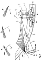
- FIG. 1 shows a road paver or a road tar machine 1 when tarring a road 2.
- Part of the road 2 is already tarred, which consequently is a machined area 2a.
- the other part of street 2 is not yet tarred and thus provides a surface to be machined 2b represents.
- the device for three-dimensional control of the paver 1 a rotating laser 3, which is removed from the construction machine at a predetermined Position is positioned and a tilt device 4 has. Furthermore, a first receiving device 5, such as B. a GPS receiver on the construction machine 1 provided that receives signals 7a-c from three satellites 9a-c. A second receiving device 11, such as. B. a Laser receiver is attached to the construction machine 1 and receives an altitude signal 13 which is output from the rotating laser 3 is produced. The height signal 13 is a light plane 13a, which is generated by the rotating laser beam.
- a Processing device 15 is in the vicinity of the rotating laser 3 arranged and with the same via a connector 17, such as B. a cable, an optical fiber or the like, connected.
- a transmission device is also on the construction machine 1 19, such as B. a radio antenna attached, which is the information obtained by the received GPS signal 7 be obtained by means of a transmission signal 21 to a Antenna 15a of the processing device 15 sends.
- the construction machine 1 is controlled in such a way that that the surface 2a processed according to predetermined solidates becomes.
- an actual position of the construction machine 1 from the GPS signal 7 and from the altitude signal 13 determines how it is in following will be described in more detail, the actual position the construction machine 1 compared with a target position is to send appropriate correction signals to the Output construction machine 1 to make a corresponding correction to effect the construction machine 1.
- the rotating laser 3 is a conventional rotating laser, which has an axis of rotation by means of the inclination device 4 can be inclined.
- the processing facility 15 controls the inclination of the rotating laser 3 in such a way that the light plane 13a on the laser receiver 11 a has a predetermined reference height, as is the case with the Fig. 3-5 is explained in more detail.
- the laser receiver 11 is a linear laser receiver with a linear output signal, that is, an output signal level of the laser receiver 11 directly proportional to the determined relative distance to the reference height in vertical direction, so that especially when activated of proportional valves (not shown) of the construction machine 1 there is an advantage in the dynamics of the control system.
- the laser receiver 11 is connected to a connecting rod 18 a tar application device 20 of the paver 1 appropriate. In this way, the laser receiver 11 is for the height signal 13 without further or without shadowing accessible through other parts of the paver 1.
- This attachment also ensures that the Height (e.g. vertical distance from sea level) of the laser receiver 11 from a working height of the tar application device 20 only differs by a constant distance.
- the processing device 15 receives via the transmission signals 21 Information from the GPS receiver 5.
- the GPS receiver 5 calculates from that of the GPS satellites 9 transmitted GPS signal 7 two coordinates of the construction machine 1 with respect to two axes, the longitude and latitude correspond (with respect to the horizontal) and sends these to the processing device 15.
- the processing device 15 controls according to these coordinates with the help the predetermined absolute position of the rotary laser 3 and the target data the inclination of the rotating laser 3 such that the laser plane 13a at the laser receiver 11 is a Has reference height, as referring to below 3-5 is described in more detail.
- the processing device determines 15 the reference height of the construction machine 1 from the target data and the GPS coordinates.
- the laser receiver 11 receives the height signal 13 or the light plane 13a and sends to a corrector 31 a signal that the deviation of the actual height of the construction machine 1 or the work tool 20 from the reference height of the light plane 13a, which is present on the laser receiver.
- a corrector 31 a signal that the deviation of the actual height of the construction machine 1 or the work tool 20 from the reference height of the light plane 13a, which is present on the laser receiver.
- the laser receiver 11 by means of the transmission device 19 (FIG. 1) the vertical Distance of the construction machine 1 relative to the reference height or the deviation of the actual height from the reference height Processing device 15 outputs.
- the processing facility 15 calculated from this relative distance and the Reference height the third coordinate of the construction machine 1 with respect a vertical axis and compares the three coordinates, d. H. the longitude value, the latitude value and the Height of the construction machine 1 with predetermined target values or a target area.
- the correction device 31 can, for example, be a or have several signal lamps that a driver of the construction machine 1 course or position changes that may need to be made Show.
- the correction device 31 can also with the steering system (not shown) of the construction machine 1 be connected to steer the course of the construction machine 1.
- the correction device 31 for example the working height of a tar application device 32 (FIG. 1) of the road tar machine 1 change to adapt the working height to the solo height.
- 3-5 is the setting of the angle of inclination the axis of rotation of the rotary laser 3 according to the preferred Described embodiment.
- the following equations is based on a right-angled, fixed coordinate system, where the x and y axes are longitude, for example or latitude, and the z-axis the height or indicates the distance to sea level.
- the used Coordinates are in a Gauss-Krüger coordinate system captured.
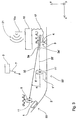
- FIG. 3 shows a simplified two-dimensional representation of the present invention.
- the underlying rectangular coordinate system shown with the z-axis up, the x-axis to the left and the y-axis directed towards the viewer is.
- the processing facility 15 is via the connector 17 to the rotating laser 3 connected, which has the inclination device 4.
- An arrow 35, 35 ' represents the rotating laser beam of the rotary laser 3, the head 3a, 3a 'of each Position 33, 33 'of the construction machine 1, 1' on the laser receiver 11, 11 'is directed.
- the reference number 9 is intended to be block-like represent the GPS satellites that emit the GPS signal 7.
- the laser beam 35, 35 'emitted by the rotating laser 3 serves as a height reference.
- the head 3a, 3a 'of the rotating laser 3 can be rotated by the inclination device 4 on two mutually perpendicular axes by the angles ⁇ x and ⁇ y , whereby the spatial position of the circular laser plane can be changed such that the rotating laser 3 each point in Can reach space.
- the location (X L , Y L , Z L ) of the rotating laser 3 is measured at the beginning.
- the current location coordinates (X M , Y M ) of a moving road construction machine 1 are determined by the GPS receiver 3 and sent to the processing device 15 via the transmission signal 21.
- the mutually dependent inclination angles ⁇ x and ⁇ y for the corresponding inclination axes of the rotary laser head 3a can be determined from the coordinates X L , Y L , Z L , X M , Y M and Z S thus known.
- the laser After the inclination of the rotary laser head 3a by the angles ⁇ x and ⁇ y , the laser now specifies the reference height Z S at the corresponding location (X M , Y M ).
- the mutually perpendicular inclination axes of the rotary laser 3 are rotated in succession.
- FIG. 5 shows the case in which the change in height hx of the laser plane 13a2 of FIG. 4 is not sufficient to effect the required change in height Z S -Z L. For this reason, the laser plane 13a2 inclined about the y-axis is inclined about the x'-axis. As can be seen in FIG. 5, the difference in height h y is brought about by this second inclination, so that the twice inclined laser plane 13a3 specifies the solid height Z S at the coordinates (X M , Y M ).
- ⁇ y arctan (h y /
- ) arctan ((Z S - H x ) /
- ) arctan ((Z S -tan ( ⁇ x ) *
- the reference height Z S can thus be predetermined for the laser receiver 11, so that the laser receiver 11 can determine the distance between the working height of the tar application device 20 and the desired position.
- the first receiving device 5 in the preferred Embodiment is shown as a GPS receiver, the first receiving device 5 can also include additional devices to improve the measurement accuracy to to be able to simulate the GPS signal even with shadowing.
- the GPS receiver 5 and the laser receiver 11 as well as the correction device 31 and / or the transmission device 19 can be integrated in one package, so that the number of Components in the construction machine 1 is reduced.
- the processing device 15 with the rotating laser 3 be in one piece, so that the number of necessary Components is further reduced.
- a laser with a rotating device and a tilting device is used to generate the height signal, wherein no laser plane is spanned, but a laser beam is always directed onto the laser receiver and the solo height.
- the determined absolute horizontal position X M , Y M of the construction machine 1 the predetermined absolute position (X L , Y L , Z L ) of the laser and the reference height ZS (X M , Y M ) become an angle of rotation for the Rotating device and an inclination angle for the inclination device are calculated.
- the laser receiver can also be an ordinary multi-channel Laser array or other suitable device to receive the altitude signal.
- the processing device can, for example, be a personal computer be, which has a memory in which the Setpoints of the construction project (site shape) are saved.
Applications Claiming Priority (2)
| Application Number | Priority Date | Filing Date | Title |
|---|---|---|---|
| DE19940404 | 1999-08-25 | ||
| DE19940404A DE19940404C2 (de) | 1999-08-25 | 1999-08-25 | Verfahren und Vorrichtung zum dreidimensionalen Steuern einer Baumaschine |
Publications (2)
| Publication Number | Publication Date |
|---|---|
| EP1079029A2 true EP1079029A2 (fr) | 2001-02-28 |
| EP1079029A3 EP1079029A3 (fr) | 2004-03-10 |
Family
ID=7919624
Family Applications (1)
| Application Number | Title | Priority Date | Filing Date |
|---|---|---|---|
| EP00118315A Withdrawn EP1079029A3 (fr) | 1999-08-25 | 2000-08-23 | Méthode et appareil pour la commande en trois dimensions d'une machine de construction |
Country Status (2)
| Country | Link |
|---|---|
| EP (1) | EP1079029A3 (fr) |
| DE (1) | DE19940404C2 (fr) |
Cited By (15)
| Publication number | Priority date | Publication date | Assignee | Title |
|---|---|---|---|---|
| US6948267B2 (en) | 2001-05-11 | 2005-09-27 | Kalannin Kaspek Oy | Device for optimization of the thickness of an ice layer |
| EP1672122A1 (fr) | 2004-12-17 | 2006-06-21 | Leica Geosystems AG | Procédé et appareil pour contrôler une machine de construction de chaussée |
| DE102006009404B3 (de) * | 2006-02-26 | 2007-07-05 | Gräf, Stefan | Anordnung und Verfahren zur Positionsbestimmung mit einem Rotationslaser |
| EP1607717A3 (fr) * | 2004-06-15 | 2007-12-19 | Kabushiki Kaisha Topcon | Système de mesure de position |
| EP1983299A1 (fr) * | 2007-04-16 | 2008-10-22 | MOBA - Mobile Automation AG | Appareil et procédé pour la détermination de l'élévation d'outils de travail au moyen d'un système laser |
| EP2040030A1 (fr) * | 2007-09-24 | 2009-03-25 | Leica Geosystems AG | Procédé de détermination de la position |
| US7510247B2 (en) | 2003-03-17 | 2009-03-31 | Kalannin Kaspek Oy | Ice resurfacing machine as well as system and method for ice maintenance |
| WO2009055955A1 (fr) * | 2007-11-01 | 2009-05-07 | Pius Kuster | Procédé et dispositif de détermination d'un objet à partir de mesures hybrides |
| US8794868B2 (en) | 2007-06-21 | 2014-08-05 | Leica Geosystems Ag | Optical guidance system for a laying engine for producing a concrete or asphalt top layer |
| AT517924A1 (de) * | 2015-11-10 | 2017-05-15 | Ing Günther Lehmann Dipl | Markiersystem |
| WO2017152227A1 (fr) * | 2016-03-08 | 2017-09-14 | Earley Ross | Vérification de niveau par laser |
| DE102011054224B4 (de) | 2011-01-24 | 2019-06-19 | Trimble Inc. (n.d.Ges.d.Staates Delaware) | Laserreferenzsystem |
| DE102017012010A1 (de) * | 2017-12-22 | 2019-06-27 | Wirtgen Gmbh | Selbstfahrende Baumaschine und Verfahren zum Steuern einer selbstfahrenden Baumaschine |
| CN110004800A (zh) * | 2019-04-10 | 2019-07-12 | 安徽开源路桥有限责任公司 | 基于3d数字控制系统的沥青混凝土路面施工设备及施工方法 |
| CN113983954A (zh) * | 2021-10-19 | 2022-01-28 | 中铁大桥科学研究院有限公司 | 一种测量桥面线形的方法及装置 |
Families Citing this family (7)
| Publication number | Priority date | Publication date | Assignee | Title |
|---|---|---|---|---|
| DE102005024676A1 (de) * | 2004-12-21 | 2006-07-06 | Bosch Rexroth Aktiengesellschaft | System zur Lageerfassung und -regelung für Arbeitsarme mobiler Arbeitsmaschinen |
| EP1677125A1 (fr) | 2004-12-28 | 2006-07-05 | Leica Geosystems AG | Procédé et laser rotatif pour la détermination d'une information de positionnement d'au moins un objet |
| US7588088B2 (en) * | 2006-06-13 | 2009-09-15 | Catgerpillar Trimble Control Technologies, Llc | Motor grader and control system therefore |
| DE102007018352A1 (de) * | 2007-04-18 | 2008-10-30 | Wacker Construction Equipment Ag | Bodenschneidvorrichtung mit automatischer Zielführung |
| DE102010060654A1 (de) * | 2010-11-18 | 2012-05-24 | Status Pro Maschinenmesstechnik Gmbh | Verfahren zum Vermessen einer Oberfläche eines Bauteiles oder Bauwerkes |
| EP2514873B8 (fr) | 2011-04-18 | 2020-05-06 | Joseph Vögele AG | Système et procédé d'application d'un revêtement routier |
| EP2515255A1 (fr) | 2011-04-18 | 2012-10-24 | Joseph Vögele AG | Appareil de lecture portable pour la caractérisation d'un engin de chantier |
Citations (3)
| Publication number | Priority date | Publication date | Assignee | Title |
|---|---|---|---|---|
| US5375663A (en) * | 1993-04-01 | 1994-12-27 | Spectra-Physics Laserplane, Inc. | Earthmoving apparatus and method for grading land providing continuous resurveying |
| EP0919837A2 (fr) * | 1997-11-14 | 1999-06-02 | Kabushiki Kaisha TOPCON | Système de communication pour un instrument géodesique |
| EP0950874A2 (fr) * | 1998-03-06 | 1999-10-20 | Kabushiki Kaisha TOPCON | Système de commande pour machines de chantier |
Family Cites Families (2)
| Publication number | Priority date | Publication date | Assignee | Title |
|---|---|---|---|---|
| US5549412A (en) * | 1995-05-24 | 1996-08-27 | Blaw-Knox Construction Equipment Corporation | Position referencing, measuring and paving method and apparatus for a profiler and paver |
| DE19755324A1 (de) * | 1997-12-12 | 1999-06-17 | Michael Dipl Ing Sartori | Verfahren und Vorrichtung zum Steuern eines Fahrzeugs |
-
1999
- 1999-08-25 DE DE19940404A patent/DE19940404C2/de not_active Expired - Fee Related
-
2000
- 2000-08-23 EP EP00118315A patent/EP1079029A3/fr not_active Withdrawn
Patent Citations (3)
| Publication number | Priority date | Publication date | Assignee | Title |
|---|---|---|---|---|
| US5375663A (en) * | 1993-04-01 | 1994-12-27 | Spectra-Physics Laserplane, Inc. | Earthmoving apparatus and method for grading land providing continuous resurveying |
| EP0919837A2 (fr) * | 1997-11-14 | 1999-06-02 | Kabushiki Kaisha TOPCON | Système de communication pour un instrument géodesique |
| EP0950874A2 (fr) * | 1998-03-06 | 1999-10-20 | Kabushiki Kaisha TOPCON | Système de commande pour machines de chantier |
Cited By (28)
| Publication number | Priority date | Publication date | Assignee | Title |
|---|---|---|---|---|
| US6948267B2 (en) | 2001-05-11 | 2005-09-27 | Kalannin Kaspek Oy | Device for optimization of the thickness of an ice layer |
| US7510247B2 (en) | 2003-03-17 | 2009-03-31 | Kalannin Kaspek Oy | Ice resurfacing machine as well as system and method for ice maintenance |
| EP1607717A3 (fr) * | 2004-06-15 | 2007-12-19 | Kabushiki Kaisha Topcon | Système de mesure de position |
| US7643923B2 (en) | 2004-12-17 | 2010-01-05 | Leica Geosystems Ag | Method and device for monitoring a road processing machine |
| EP1672122A1 (fr) | 2004-12-17 | 2006-06-21 | Leica Geosystems AG | Procédé et appareil pour contrôler une machine de construction de chaussée |
| WO2006064062A1 (fr) * | 2004-12-17 | 2006-06-22 | Leica Geosystems Ag | Procede et systeme pour controler un engin de travaux routiers |
| DE102006009404B3 (de) * | 2006-02-26 | 2007-07-05 | Gräf, Stefan | Anordnung und Verfahren zur Positionsbestimmung mit einem Rotationslaser |
| EP1983299A1 (fr) * | 2007-04-16 | 2008-10-22 | MOBA - Mobile Automation AG | Appareil et procédé pour la détermination de l'élévation d'outils de travail au moyen d'un système laser |
| US7760369B2 (en) | 2007-04-16 | 2010-07-20 | Moba-Mobile Automation Ag | Apparatus and method for determining an elevation of working tools based on a laser system |
| US8794868B2 (en) | 2007-06-21 | 2014-08-05 | Leica Geosystems Ag | Optical guidance system for a laying engine for producing a concrete or asphalt top layer |
| US8422032B2 (en) | 2007-09-24 | 2013-04-16 | Leica Geosystems Ag | Position determination method |
| AU2008303962B2 (en) * | 2007-09-24 | 2011-03-24 | Leica Geosystems Ag | Position determination method |
| CN101809407B (zh) * | 2007-09-24 | 2012-09-05 | 莱卡地球系统公开股份有限公司 | 位置确定方法 |
| WO2009039929A1 (fr) * | 2007-09-24 | 2009-04-02 | Leica Geosystems Ag | Procédé de détermination de position |
| EP2040030A1 (fr) * | 2007-09-24 | 2009-03-25 | Leica Geosystems AG | Procédé de détermination de la position |
| WO2009055955A1 (fr) * | 2007-11-01 | 2009-05-07 | Pius Kuster | Procédé et dispositif de détermination d'un objet à partir de mesures hybrides |
| DE102011054224B4 (de) | 2011-01-24 | 2019-06-19 | Trimble Inc. (n.d.Ges.d.Staates Delaware) | Laserreferenzsystem |
| AT517924A1 (de) * | 2015-11-10 | 2017-05-15 | Ing Günther Lehmann Dipl | Markiersystem |
| AT517924B1 (de) * | 2015-11-10 | 2019-10-15 | Dipl Ing Guenther Lehmann | Markiersystem |
| WO2017152227A1 (fr) * | 2016-03-08 | 2017-09-14 | Earley Ross | Vérification de niveau par laser |
| CN109154500A (zh) * | 2016-03-08 | 2019-01-04 | 斯塔夫控股私人有限公司 | 激光水准检查 |
| US11280607B2 (en) | 2016-03-08 | 2022-03-22 | Staff Holdings Pty Ltd | Laser level checking |
| DE102017012010A1 (de) * | 2017-12-22 | 2019-06-27 | Wirtgen Gmbh | Selbstfahrende Baumaschine und Verfahren zum Steuern einer selbstfahrenden Baumaschine |
| EP3502821B1 (fr) * | 2017-12-22 | 2021-03-24 | Wirtgen GmbH | Engin de construction et procédé de commande d'un engin de construction |
| US11029704B2 (en) | 2017-12-22 | 2021-06-08 | Wirtgen Gmbh | Self-propelled construction machine and method for controlling a self-propelled construction machine |
| CN110004800A (zh) * | 2019-04-10 | 2019-07-12 | 安徽开源路桥有限责任公司 | 基于3d数字控制系统的沥青混凝土路面施工设备及施工方法 |
| CN113983954A (zh) * | 2021-10-19 | 2022-01-28 | 中铁大桥科学研究院有限公司 | 一种测量桥面线形的方法及装置 |
| CN113983954B (zh) * | 2021-10-19 | 2023-08-11 | 中铁大桥科学研究院有限公司 | 一种测量桥面线形的方法及装置 |
Also Published As
| Publication number | Publication date |
|---|---|
| DE19940404C2 (de) | 2001-07-12 |
| DE19940404A1 (de) | 2001-03-29 |
| EP1079029A3 (fr) | 2004-03-10 |
Similar Documents
| Publication | Publication Date | Title |
|---|---|---|
| DE19940404C2 (de) | Verfahren und Vorrichtung zum dreidimensionalen Steuern einer Baumaschine | |
| DE102007051198B4 (de) | System und Verfahren zur automatischen Einstellung eines Arbeitsgerätes | |
| EP2193333B1 (fr) | Procédé de détermination de la position | |
| AT403066B (de) | Verfahren zum ermitteln der abweichungen der ist-lage eines gleisabschnittes | |
| EP3106899B1 (fr) | Systeme de commande de vehicule reference | |
| EP1606965B1 (fr) | Procede et dispositif pour adapter un modele de reseau radio aux conditions d'un reseau radio reel | |
| DE69635569T2 (de) | Vorrichtung zum Bestimmen der lokalen Position eines Autos auf einer Strasse | |
| DE102012011518B3 (de) | Geodätisches ziel und positionsbestimmungssystem | |
| EP3502821A1 (fr) | Engin de construction et procédé de commande d'un engin de construction | |
| DE102017221134A1 (de) | Verfahren und Vorrichtung zum Betreiben eines mobilen Systems | |
| EP0964958A1 (fr) | Procede et dispositif pour fraiser des surfaces de circulation routiere | |
| DE102004062275A1 (de) | Verfahren und Vorrichtung zum Ermitteln eines Kalibrierparameters einer Stereokamera | |
| EP1842077A2 (fr) | Procede et laser rotatif pour determiner une information de position d'au moins un objet | |
| EP0796420A1 (fr) | Procede et dispositif d'arpentage et de marquage | |
| EP2511658A1 (fr) | Système de mesure et procédé de détermination de nouveau point | |
| DE102006019917A1 (de) | Verfahren und Vorrichtung zur Sicherung der Maßhaltigkeit von mehrsegmentigen Konstruktionsstrukturen beim Zusammenbau | |
| EP0858931A2 (fr) | Dispositif pour commander la portée des phases d'un véhicule | |
| DE102007034354A1 (de) | Verfahren und Vorrichtung zum Schätzen von Verhalten eines Fahrzeugs unter Verwendung von GPS-Signalen | |
| EP2603767A1 (fr) | Procédé d'étalonnage d'un système de mesure et dispositif de mise en uvre dudit procédé | |
| EP3839146A1 (fr) | Procédé de fraisage des surfaces de circulation à l'aide d'un rouleau fraiseur ainsi que fraiseuse permettant la mise en uvre du procédé de fraisage des surfaces de circulation | |
| DE19544112A1 (de) | Verfahren zur Generierung digitaler Geländemodelle | |
| DE102007049123A1 (de) | Markier- und/oder Nivelliervorrichtung sowie Verfahren | |
| EP2998699B1 (fr) | Procédé de traitement d'une référence de hauteur pour un outil d'un engin, dispositif et procédé de réglage en hauteur d'un outil d'un engin, engin | |
| EP1408344B1 (fr) | Dispositif et méthode géodésique utilisant un laser à balayage | |
| DE102011054224B4 (de) | Laserreferenzsystem |
Legal Events
| Date | Code | Title | Description |
|---|---|---|---|
| PUAI | Public reference made under article 153(3) epc to a published international application that has entered the european phase |
Free format text: ORIGINAL CODE: 0009012 |
|
| 17P | Request for examination filed |
Effective date: 20000823 |
|
| AK | Designated contracting states |
Kind code of ref document: A2 Designated state(s): AT BE CH CY DE DK ES FI FR GB GR IE IT LI LU MC NL PT SE |
|
| AX | Request for extension of the european patent |
Free format text: AL;LT;LV;MK;RO;SI |
|
| PUAL | Search report despatched |
Free format text: ORIGINAL CODE: 0009013 |
|
| AK | Designated contracting states |
Kind code of ref document: A3 Designated state(s): AT BE CH CY DE DK ES FI FR GB GR IE IT LI LU MC NL PT SE |
|
| AX | Request for extension of the european patent |
Extension state: AL LT LV MK RO SI |
|
| RIC1 | Information provided on ipc code assigned before grant |
Ipc: 7G 01S 17/66 B Ipc: 7E 02F 3/84 B Ipc: 7E 01C 19/00 B Ipc: 7E 02F 9/20 A |
|
| STAA | Information on the status of an ep patent application or granted ep patent |
Free format text: STATUS: THE APPLICATION HAS BEEN WITHDRAWN |
|
| 18W | Application withdrawn |
Effective date: 20040330 |