EP1078845A1 - Dispositif antivol pour roue de secours apparente - Google Patents
Dispositif antivol pour roue de secours apparente Download PDFInfo
- Publication number
- EP1078845A1 EP1078845A1 EP00402361A EP00402361A EP1078845A1 EP 1078845 A1 EP1078845 A1 EP 1078845A1 EP 00402361 A EP00402361 A EP 00402361A EP 00402361 A EP00402361 A EP 00402361A EP 1078845 A1 EP1078845 A1 EP 1078845A1
- Authority
- EP
- European Patent Office
- Prior art keywords
- wheel
- theft device
- cover
- rim
- safety cover
- Prior art date
- Legal status (The legal status is an assumption and is not a legal conclusion. Google has not performed a legal analysis and makes no representation as to the accuracy of the status listed.)
- Granted
Links
- 239000000463 material Substances 0.000 claims description 7
- 238000000465 moulding Methods 0.000 claims description 5
- 230000002093 peripheral effect Effects 0.000 claims description 5
- 239000004033 plastic Substances 0.000 claims description 5
- 230000000295 complement effect Effects 0.000 description 3
- 238000005553 drilling Methods 0.000 description 2
- 210000005069 ears Anatomy 0.000 description 2
- 238000002347 injection Methods 0.000 description 2
- 239000007924 injection Substances 0.000 description 2
- 238000009434 installation Methods 0.000 description 2
- 238000005034 decoration Methods 0.000 description 1
- 238000004519 manufacturing process Methods 0.000 description 1
- 239000002184 metal Substances 0.000 description 1
- 239000002991 molded plastic Substances 0.000 description 1
Images



Classifications
-
- B—PERFORMING OPERATIONS; TRANSPORTING
- B62—LAND VEHICLES FOR TRAVELLING OTHERWISE THAN ON RAILS
- B62D—MOTOR VEHICLES; TRAILERS
- B62D43/00—Spare wheel stowing, holding, or mounting arrangements
- B62D43/007—Anti-theft devices for spare wheels
Definitions
- the invention relates to an anti-theft device for a wheel. of apparent relief which is mounted outside the bodywork of a motor vehicle.
- the invention relates more particularly to a device anti-theft device for an apparent spare tire which is mounted the exterior of the body of a motor vehicle, in particular a recreational vehicle, of the type in which a front side of the spare wheel rim is mounted in axial support on a support which projects outwards from an element of the vehicle body, in particular a rear transverse opening of the vehicle, and of the type in which the rim is fixed to this support by means wheel fixing comprising at least one bolt of fixing which passes through one of the eccentric fixing holes of the wheel and comprise at least one associated fixing nut.
- the visible spare wheels are fixed to the support in two different ways, either by nuts which are screwed onto studs arranged opposite the eccentric wheel fixing holes which project towards outside and towards the rear of the vehicle from the support, i.e. by screws which pass through the eccentric fixing holes of the wheel and are received in captive nuts linked to the support.
- Such a conforming socket has the disadvantage of being small in size so that it can be easily lost which then makes disassembly of the spare wheel impossible.
- This design has the disadvantage of leaving the padlock accessible from outside the vehicle so that it can be forced or cut with a conventional bolt cutter. This operation is all the easier as the padlock loop, to be able to cross the transverse hole of the stud considered, is necessarily of small diameter.
- This design has the disadvantage of presenting limited resistance to tearing. Indeed, the tire being radially elastic, minimal deformation of the pneumatic, carried out for example using an inserted lever between the cover and the tire, or a deflation of the pneumatic, sufficient to allow the cover to be torn off.
- the invention proposes an anti-theft device which is only accessible from the inside of the vehicle.
- the invention proposes relates to a device anti-theft device for an apparent spare tire of the type described previously, characterized in that it comprises a cover of safety which in a mounted position in which it is locked from inside the vehicle, covers at least one part of the entire rear face of the wheel to prohibit access to said bolts and nuts for fixing the rim to the support.
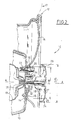
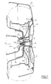
- Figures 2 and 3 show a set of anti-theft device 10 for an apparent spare tire 12 in accordance with a first embodiment of the invention, and in FIGS. 6 and 7 an anti-theft device 10 in accordance with a second embodiment of the invention.
- the device 10 is intended to be used to prevent disassembly, from outside the vehicle (not shown) of the spare tire 12 of the vehicle which is mounted outside the vehicle body, so that prevent it from being stolen.
- Such a spare wheel 12 is in particular a wheel of the type of those which one can meet on vehicles of hobbies, such as all-terrain vehicles also called "4 ⁇ 4" vehicles.
- the spare wheel 12 is conventionally mounted on an element 13 of the vehicle body, in particular a rear transverse opening 13 of the vehicle, along an axis A which is longitudinal and substantially perpendicular to the opening 13.
- the spare wheel 12 is composed of a rim 15 and of a tire 17.
- a transverse front face 14 of the rim 15 of the spare wheel 12 is mounted in axial support on a support 16 which is linked to the vehicle body element 13, and which protrudes outward therefrom.
- the rim 15 comprises fixing means on the support 16, in particular holes 18 which are offset from its axis A, and which are crossed by at least one bolt 20 which is received in at least one nut 22.
- the eccentric holes 18 are. of known manner, those which are conventionally used for fixing the wheel 12 on hubs (not shown) of the vehicle axles.
- a spare wheel 12 which is fixed on the support 16 by means of bolts 20 which are received in captive nuts 22 carried by the support 16. It will be understood that this provision is not limitative of the invention and that the fixing the spare wheel 12 on the support 16 could be also provided by studs integral with the support 16 and by additional nuts that would be tightened against a rear transverse face 26 of the rim 15.
- the anti-theft device 10 has a safety cover 24 which, in a position climb shown in Figure 2, covers at least part of the rear transverse face 26 of the wheel 12 to prohibit access to said bolts 20 and nut 22 for fixing the rim 15 on the support 16.
- the security cover 24 of the anti-theft device 10 prevents access to bolts 20 covering at least the rear transverse face 26 along a disc which covers the fixing plane of the bolts 20.
- the safety cover 24 comprises a cup 25 with a diameter D 25 which is slightly greater than the diameter D 26 of the rear transverse face 26 of the rim 15. In this way , the safety cover 24, once mounted, prevents access to the means for fixing the rim 15, and in particular to the bolts 20 for fixing the rim 15 to the support 16.
- the cover security 24 has a locking rod 28 which is intended to pass through a central bore 32 of the rim 15, the support 16, and the element 13 of the vehicle body, and of which the end 30 can be locked from the inside of the element 13 bodywork of the vehicle using a locking member 35.
- this safety cover 24 is shown. which is positioned coaxially with the axis A so that it is ready to be mounted on the rim 15 of the wheel 12 to make prohibiting access to bolts 20.
- the central bore 32 of axis A of the rim 15 allows, during the prior installation of the wheel 12 on the support 16, to center it by means of a hub 34 for centering, of axis A, which is carried by the support 16.
- This centering hub 34 penetrates into the central bore 32 wheel 16 when the latter is placed in position on the support 16 and bolted in accordance with Figures 2 and 3.
- the hub 34 for centering the support 16 is tubular and has a bore 36 which is intended to receive a sleeve 38 complementary, of cylindrical generator, which is part of the 24 security cover.
- the cylindrical sleeve 38 extends axially towards the front from the cup 25.
- the sleeve 38 consists of the meeting of parts 39 of ribs 40, and is linked to a front face 27 of the cup 25 by radial ribs 40 which radiate around the general axis of the safety cover 24. These ribs 40 extend towards the front from the front face 27 of the cup 25 and are evenly distributed angularly, so that they also allow the cup 25 to be stiffened.
- the safety cover 24, i.e. the cup 25 and the ribs 40 is produced by molding a plastic material, in particular by injection, and the ribs 40, which have a certain elasticity, allow easy release of the safety cover 24.
- FIG. 3 shows the safety cover 24 the locking rod 28 of which is threaded is locked the interior of the vehicle body element 13 by a wing nut 35.
- the safety cover 24 is thus locked axially.
- the locking rod 28 could for example be a smooth rod 28 whose end 30 would be pierced transversely and which would be immobilized axially by a conforming pin.
- the locking rod 28 is embedded in the molded plastic from cover 24.
- the user bolts the spare tire 12 to the support beforehand 26, then put the safety cover 24 on it, and finally opens the door 13 so as to have access to the wing nut 35 that it screws onto the end 30 of the threaded rod 28, in accordance in Figure 3.
- the anti-theft device 10 comprises means for stopping the rotation of the safety cover 24 relative to the vehicle body, and in particular relative to the opening 13, so as to prevent disassembly of the safety cover 24 by unscrewing the rod threaded 28.
- stop means comprise at least one eccentric sleeve 44, which extends from the front face 27 of the safety cover 24, which is intended, for mounting, to cooperate with the means for fixing the wheel 12.
- two holes 18 of wheel 12 do not receive 20 fixing bolts.
- the two holes 18 thus left free thus define two attachment points of reference for the stop means.
- a rib 40a of the cover 24 carries a first stud axial 44a which is of a diameter substantially equal to the diameter an associated free hole 18a for fixing the wheel 12, and which is located radially at the same distance from axis A as this drilling 18.
- the first pad 44a has the shape of a tube which has at least two axial slots 46.
- the edges of these slots 46 are likely to be close to allow passage of the axial stud 44a in the drilling 18a, then move away so that the periphery of the axial stud 44a is supported on the edges of the free bore 18a, as shown in figure 4.
- a rib 40b of the cover 24 comprises a second axial stud 44b, which is of a diameter slightly greater than the diameter of a hole 18 wheel attachment partner 12, which is also left free when prior mounting of the wheel 12 on the support 26.
- first 44a and second 44b studs determine an unequivocal position of the safety cover 24, and the first pad 44 rotates the safety cover 24 with respect to wheel 12, and therefore also with respect to to the vehicle body.
- the cover security 24 is also advantageous in that it allows provide a rear face 29 of the cup 25, shown in the Figure 1, a decoration or a hubcap that will occupy always the same position when the safety cover is put on in place.
- the cover 24 of security includes a diamond-shaped molding 31, which sees the shape on the side of the front face 27 of the cup 25.
- the security cover 24 of the anti-theft device 10 prevents access to bolts 20 completely covering a rear face 50 of the wheel.
- the cover of security 24 produced according to the second embodiment of the invention therefore covers at least the rear face 26 of the rim and a rear face 52 of the tire 17.
- the safety cover has a central part 54, which covers the rear face 26 of the rim 15, and an annular part peripheral 56 forming a cover which surrounds the free surface 58 the tire of the wheel, i.e. its tread, and its rear face 52 previously described.
- the safety cover 24 once mounted, prohibits access to the means for fixing the rim 15, and in particular to the bolts 20 for fixing the rim 15 to the support 16.
- the central part 54 has substantially the shape of a cup with a diameter D 54 which is greater than the diameter D 26 of the transverse rear face 26 of the rim 15, and which is fixed to a front face 60 of the peripheral annular part 56 forming the cover of the cover 24, in particular by means of peripheral screwing means 62.
- the safety cover 24 comprises a locking rod 28 which is intended for pass through a central bore 32 of the rim 15, the support 16, and the vehicle body element 13, the end of which 30 can be locked from inside the element 13 of vehicle body using a locking member 35.
- FIG 6 there is shown a safety cover 24 which is positioned coaxially with the axis A so that it is ready to be mounted on wheel 12 to carry out the ban on access to bolts 20.
- the central bore 32 of axis A of the rim 15 allows, during the prior installation of the wheel 12 on the support 16, to center it via the hub 34 for centering, of axis A, which is carried by the support 16.
- This centering hub 34 penetrates into the central bore 32 of wheel 16 in a manner analogous to the first mode of embodiment of the invention, as illustrated in Figures 6 and 7.
- the hub 34 for centering the support 16 is tubular and its bore 36 is intended to receive a sleeve 38 complementary cylinder-shaped material with the central part 54 of the safety cover 24.
- the sleeve cylindrical 38 extends axially forward from the central portion 54 of the cover 24.
- the sleeve 38 is pierced with so as to allow the passage of the threaded rod 28 of a screw 64 which is inserted and then crimped, during the assembly of the cover security 24, in the central part 54 of the security cover 24 through a rear opening 66.
- This rear opening is arranged opposite an orifice 68 of the cover 56 which is obstructed by a plug 70.
- the central part 54 of the cover security 24 has ribs 40 rear and 41 front radials which radiate around the general axis of the cover safety 24 to stiffen the central part 54.
- the elements of the safety cover 24 are, in a way analogous to the first embodiment, produced by molding of a plastic material, in particular by injection.
- the device anti-theft device 10 comprises means for stopping the cover from rotating. security 24 with respect to the vehicle body, and in particular relative to the opening 13, so as to prevent the disassembly of the safety cover 24 by unscrewing the rod threaded 28.
- At least three holes 18 of the wheel 12 receive fixing bolts 20.
- the three bolts 20 thus define three reference fixing points for the means of stopping.
- a transverse front face 72 of the part central 54 carries three tubular axial studs 74 each of which is of a diameter equal to the diameter of the head of a bolt 20 cited above. These studs 74 are located radially at the same distance from axis A as bolts 20.
- each tubular stud 74 receives the head of the corresponding bolt 20 when the cover 24 safety is placed on the wheel 12.
- These studs 74 are distributed angularly irregularly so that define a unique position for mounting the safety cover 24 on wheel 12.
- the studs 74 immobilize in rotation the safety cover 24 with respect to the wheel 12, and by therefore also in relation to the vehicle body.
- the front face 72 of the central part 54 comprises two stamps 76, which can in particular be produced from of material with the plastic material of the central part 54 of the safety cover 24, and which extend forward so to take support in the mounted position of the cover 24 on the rim 15 wheel 12 to stabilize the cover 24 and avoid vibrations.
- the device 10 makes it possible simply and lower cost locking the bolts 20 for fixing the wheel 12, and protect it from the lust of thieves.
- the second embodiment of the device 10 allows protect wheel 12 from mud splashes, which is particularly appreciable in the case of a vehicle of "4 ⁇ 4" type recreation.
Landscapes
- Engineering & Computer Science (AREA)
- Chemical & Material Sciences (AREA)
- Combustion & Propulsion (AREA)
- Transportation (AREA)
- Mechanical Engineering (AREA)
- Burglar Alarm Systems (AREA)
- Lock And Its Accessories (AREA)
- Body Structure For Vehicles (AREA)
Abstract
Description
- le cache de sécurité est verrouillé de l'intérieur du véhicule par l'intermédiaire d'une tige de verrouillage qui traverse une ouverture de la jante de la roue et un passage commun du support et de l'élément de carrosserie du véhicule, et d'un organe de verrouillage qui est fixé à l'extrémité de la tige de verrouillage faisant saillie à l'intérieur de l'élément de carrosserie du véhicule,
- la tige de verrouillage est une tige filetée du cache dont l'extrémité libre reçoit un écrou de verrouillage fixé par vissage depuis l'intérieur de l'élément de carrosserie,
- la tige filetée est coaxiale à la roue et traverse une ouverture centrale de celle-ci,
- le cache de sécurité comporte des moyens d'arrêt en rotation par rapport à la carrosserie du véhicule pour empêcher son démontage par dévissage de la tige filetée coaxiale depuis l'extérieur du véhicule,
- les moyens d'arrêt en rotation comportent au moins un plot excentré creux, qui s'étend à partir de la face avant du cache de sécurité tournée vers la jante, et qui est destiné, au montage, à coopérer avec les moyens de fixation de la roue,
- le cache de sécurité recouvre entièrement la face arrière de la roue,
- le cache de sécurité comporte une partie centrale, qui recouvre la face arrière de la jante, et une partie annulaire périphérique formant un capot qui entoure la surface libre du pneu de la roue,
- la partie centrale et la partie annulaire du cache de sécurité sont réalisés par moulage d'un matériau plastique,
- la partie centrale du cache de sécurité est vissée sur une face avant de la partie annulaire du cache de sécurité qui est tournée vers la roue,
- la tige de verrouillage du cache de sécurité est sertie dans un noyau central de la partie centrale du cache de sécurité.
- la figure 1 est une vue en perspective d'un cache de sécurité pour un dispositif antivol selon un premier mode de réalisation de l'invention ;
- la figure 2 est une vue en coupe selon la ligne 2-2 de la figure 1 du dispositif antivol selon un premier mode de réalisation de l'invention représenté démonté ;
- la figure 3 est une vue en coupe selon la figure 2 du dispositif antivol de la figure 2 représenté monté ;
- la figure 4 est une vue en coupe selon la ligne 4-4 de la figure 1 représentant les moyens d'arrêt en rotation du cache de sécurité selon le premier mode de réalisation de l'invention ;
- la figure 5 est une vue en perspective éclatée d'un cache de sécurité pour un dispositif antivol selon un second mode de réalisation de l'invention ;
- la figure 6 est une vue en coupe selon la ligne 6-6 de la figure 5 du dispositif antivol selon le second mode de réalisation de l'invention représenté démonté ; et
- la figure 7 est une vue selon la figure 6 du dispositif antivol de la figure 6 représenté monté.
Claims (11)
- Dispositif antivol (10) pour une roue (12) de secours apparente qui est montée à l'extérieur de la carrosserie d'un véhicule automobile, notamment d'un véhicule de loisirs, du type dans lequel une face avant (14) de la jante (15) de la roue (12) de secours est montée en appui axial sur un support (16) qui fait saillie vers l'extérieur à partir d'un élément (13) de la carrosserie du véhicule, notamment d'un ouvrant transversal arrière du véhicule, et du type dans lequel la jante (15) est fixée sur ce support par l'intermédiaire de moyens de fixation de la roue comportant au moins un boulon (20) de fixation qui traverse un des perçages (18) excentrés de fixation de la roue (12) et au moins un écrou (22) associé de fixation,
caractérisé en ce qu'il comporte un cache (24) de sécurité qui, dans une position montée dans laquelle il est verrouillé depuis l'intérieur du véhicule, recouvre au moins une partie de la totalité de la face arrière (26) de la roue (12) pour interdire l'accès aux dits boulon (20) et écrou (22) de fixation de la jante (15) sur le support (16). - Dispositif antivol (10) selon la revendication précédente, caractérisé en en ce que le cache (24) de sécurité est verrouillé de l'intérieur du véhicule par l'intermédiaire d'une tige (28) de verrouillage qui traverse une ouverture (32) de la jante (15) de la roue (12) et un passage commun (36) du support (16) et de l'élément (13) de carrosserie du véhicule, et d'un organe (35) de verrouillage qui est fixé à l'extrémité (30) de la tige (28) de verrouillage faisant saillie à l'intérieur de l'élément (13) de carrosserie du véhicule.
- Dispositif antivol (10) selon la revendication précédente, caractérisé en ce que la tige (28) de verrouillage est une tige filetée du cache (24) dont l'extrémité libre (30) reçoit un écrou (35) de verrouillage fixé par vissage depuis l'intérieur de l'élément (13) de carrosserie.
- Dispositif antivol (10) selon la revendication précédente, caractérisé en ce que la tige (28) filetée est coaxiale à la roue (12) et traverse une ouverture centrale (30) de celle-ci.
- Dispositif antivol (10) selon la revendication précédente, caractérisé en ce que le cache (24) de sécurité comporte des moyens d'arrêt (44a, 44b, 74) en rotation par rapport à la carrosserie du véhicule pour empêcher son démontage par dévissage de la tige (28) filetée coaxiale depuis l'extérieur du véhicule.
- Dispositif antivol (10) selon la revendication précédente, caractérisé en ce que les moyens d'arrêt en rotation comportent au moins un plot (44a, 44b, 74) excentré creux, qui s'étend à partir de la face avant (27, 72) du cache (24) de sécurité tournée vers la jante (15), et qui est destiné, au montage, à coopérer avec les moyens de fixation (20, 22) de la roue (12).
- Dispositif antivol (10) selon l'une quelconque des revendications précédentes, caractérisé en ce que le cache (24) de sécurité recouvre entièrement la face arrière de la roue (12).
- Dispositif antivol (10) selon la revendication précédente, caractérisé en ce que le cache (24) de sécurité comporte une partie centrale (54), qui recouvre la face arrière (26) de la jante (15), et une partie annulaire (56) périphérique formant un capot qui entoure la surface libre du pneu (17) de la roue (12).
- Dispositif antivol (10) selon la revendication précédente, caractérisé en ce que la partie centrale (54) et la partie annulaire (52) du cache de sécurité (24) sont réalisés par moulage d'un matériau plastique.
- Dispositif antivol (10) selon l'une des revendications 8 ou 9, caractérisé en ce que la partie centrale (54) du cache (24) de sécurité est vissée sur une face avant (60) de la partie (52) annulaire du cache (24) de sécurité qui est tournée vers la roue (12).
- Dispositif antivol (10) selon l'une quelconque des revendications 7 à 10, caractérisé en ce que la tige (28) de verrouillage du cache de sécurité est sertie dans un manchon (38) central de la partie centrale (54) du cache (24) de sécurité.
Applications Claiming Priority (2)
| Application Number | Priority Date | Filing Date | Title |
|---|---|---|---|
| FR9910856 | 1999-08-27 | ||
| FR9910856A FR2797838B1 (fr) | 1999-08-27 | 1999-08-27 | Dispositif antivol pour roue de secours apparente |
Publications (2)
| Publication Number | Publication Date |
|---|---|
| EP1078845A1 true EP1078845A1 (fr) | 2001-02-28 |
| EP1078845B1 EP1078845B1 (fr) | 2003-06-04 |
Family
ID=9549385
Family Applications (1)
| Application Number | Title | Priority Date | Filing Date |
|---|---|---|---|
| EP20000402361 Expired - Lifetime EP1078845B1 (fr) | 1999-08-27 | 2000-08-25 | Dispositif antivol pour roue de secours apparente |
Country Status (4)
| Country | Link |
|---|---|
| EP (1) | EP1078845B1 (fr) |
| DE (1) | DE60003124T2 (fr) |
| ES (1) | ES2194689T3 (fr) |
| FR (1) | FR2797838B1 (fr) |
Cited By (3)
| Publication number | Priority date | Publication date | Assignee | Title |
|---|---|---|---|---|
| CN106364577A (zh) * | 2015-07-24 | 2017-02-01 | 通用汽车环球科技运作有限责任公司 | 备用车轮安装系统 |
| GB2581186A (en) * | 2019-02-07 | 2020-08-12 | Jaguar Land Rover Ltd | Security device |
| WO2025017005A1 (fr) * | 2023-07-19 | 2025-01-23 | Jaguar Land Rover Limited | Couvercle verrouillable pour une fixation de roue sur un véhicule |
Citations (1)
| Publication number | Priority date | Publication date | Assignee | Title |
|---|---|---|---|---|
| EP0615895A1 (fr) * | 1993-03-18 | 1994-09-21 | Ian Lister | Dispositif de sécurité de la roue de secours d'une véhicule |
-
1999
- 1999-08-27 FR FR9910856A patent/FR2797838B1/fr not_active Expired - Fee Related
-
2000
- 2000-08-25 EP EP20000402361 patent/EP1078845B1/fr not_active Expired - Lifetime
- 2000-08-25 DE DE2000603124 patent/DE60003124T2/de not_active Expired - Fee Related
- 2000-08-25 ES ES00402361T patent/ES2194689T3/es not_active Expired - Lifetime
Patent Citations (1)
| Publication number | Priority date | Publication date | Assignee | Title |
|---|---|---|---|---|
| EP0615895A1 (fr) * | 1993-03-18 | 1994-09-21 | Ian Lister | Dispositif de sécurité de la roue de secours d'une véhicule |
Cited By (4)
| Publication number | Priority date | Publication date | Assignee | Title |
|---|---|---|---|---|
| CN106364577A (zh) * | 2015-07-24 | 2017-02-01 | 通用汽车环球科技运作有限责任公司 | 备用车轮安装系统 |
| GB2581186A (en) * | 2019-02-07 | 2020-08-12 | Jaguar Land Rover Ltd | Security device |
| GB2581186B (en) * | 2019-02-07 | 2021-07-21 | Jaguar Land Rover Ltd | Security device |
| WO2025017005A1 (fr) * | 2023-07-19 | 2025-01-23 | Jaguar Land Rover Limited | Couvercle verrouillable pour une fixation de roue sur un véhicule |
Also Published As
| Publication number | Publication date |
|---|---|
| DE60003124D1 (de) | 2003-07-10 |
| FR2797838B1 (fr) | 2001-11-16 |
| FR2797838A1 (fr) | 2001-03-02 |
| DE60003124T2 (de) | 2004-05-06 |
| ES2194689T3 (es) | 2003-12-01 |
| EP1078845B1 (fr) | 2003-06-04 |
Similar Documents
| Publication | Publication Date | Title |
|---|---|---|
| EP0497655B1 (fr) | Enjoliveur de roue, notamment de véhicule automobile | |
| EP0743053B1 (fr) | Dispositif de sécurité et de contrôle du verrouillage d'un moyeu de roue, notamment pour fauteuils roulants | |
| FR2601318A1 (fr) | Frein a machoire pour bicyclette | |
| EP1981721A2 (fr) | Dispositif de securite pour roue de vehicule | |
| EP2605921A1 (fr) | Dispositif de sécurité pour une roue d'un véhicule | |
| FR2498528A1 (fr) | Perfectionnement au montage d'un enjoliveur sur une roue de vehicule | |
| EP0561704B1 (fr) | Roulement de butée de suspension pour véhicule et son procédé de montage | |
| EP0764551A1 (fr) | Moyeu de roue notamment pour cycle | |
| FR3113862A1 (fr) | Dispositif de protection pour flanc de pneu | |
| EP1078845B1 (fr) | Dispositif antivol pour roue de secours apparente | |
| EP2614201B1 (fr) | Verrou pour systeme de verrouillage de vehicule automobile | |
| FR2722449A1 (fr) | Couvre-moyeu pour roues de vehicules automobile | |
| FR3029457A1 (fr) | Ensemble comportant une jante et un enjoliveur equipe d’un moyeu de blocage axial | |
| FR2749243A1 (fr) | Agencement pour le montage sur la caisse d'un vehicule automobile d'un mecanisme d'essuie-glace | |
| EP0539253B1 (fr) | Frein à disque | |
| WO2021144527A1 (fr) | Dispositif de transmission et engin automoteur équipé d'un tel dispositif de transmission | |
| EP3634775B1 (fr) | Roue de montage pour véhicule automobile et ensemble monté comportant une telle roue de montage | |
| EP2221494A1 (fr) | Dispositif de fixation d'un palier radial d'un arbre de transmission d'un véhicule | |
| FR2459159A1 (fr) | Dispositif antivol a blocage de direction pour vehicules automobiles | |
| WO2017125652A1 (fr) | Antivol d'enjoliveur de roue de vehicule | |
| FR2567077A1 (fr) | Enjoliveur antivol pour roue de vehicule | |
| FR2715199A1 (fr) | Dispositif de fixation d'un équipement sur la carrosserie d'un véhicule automobile. | |
| FR2517257A1 (fr) | Ensemble enjoliveur de roue de vehicule | |
| FR2745609A1 (fr) | Attache rapide de type a baionnette | |
| FR2464835A1 (fr) | Dispositif antiderapant adaptable sur une roue a pneumatique de vehicule |
Legal Events
| Date | Code | Title | Description |
|---|---|---|---|
| PUAI | Public reference made under article 153(3) epc to a published international application that has entered the european phase |
Free format text: ORIGINAL CODE: 0009012 |
|
| AK | Designated contracting states |
Kind code of ref document: A1 Designated state(s): BE DE ES |
|
| AX | Request for extension of the european patent |
Free format text: AL;LT;LV;MK;RO;SI |
|
| 17P | Request for examination filed |
Effective date: 20010814 |
|
| AKX | Designation fees paid |
Free format text: BE DE ES |
|
| RAP1 | Party data changed (applicant data changed or rights of an application transferred) |
Owner name: RENAULT S.A.S. |
|
| GRAH | Despatch of communication of intention to grant a patent |
Free format text: ORIGINAL CODE: EPIDOS IGRA |
|
| GRAH | Despatch of communication of intention to grant a patent |
Free format text: ORIGINAL CODE: EPIDOS IGRA |
|
| GRAA | (expected) grant |
Free format text: ORIGINAL CODE: 0009210 |
|
| AK | Designated contracting states |
Designated state(s): BE DE ES |
|
| REF | Corresponds to: |
Ref document number: 60003124 Country of ref document: DE Date of ref document: 20030710 Kind code of ref document: P |
|
| PLBE | No opposition filed within time limit |
Free format text: ORIGINAL CODE: 0009261 |
|
| STAA | Information on the status of an ep patent application or granted ep patent |
Free format text: STATUS: NO OPPOSITION FILED WITHIN TIME LIMIT |
|
| 26N | No opposition filed |
Effective date: 20040305 |
|
| PGFP | Annual fee paid to national office [announced via postgrant information from national office to epo] |
Ref country code: DE Payment date: 20050812 Year of fee payment: 6 |
|
| PGFP | Annual fee paid to national office [announced via postgrant information from national office to epo] |
Ref country code: ES Payment date: 20050817 Year of fee payment: 6 |
|
| PGFP | Annual fee paid to national office [announced via postgrant information from national office to epo] |
Ref country code: BE Payment date: 20050914 Year of fee payment: 6 |
|
| PG25 | Lapsed in a contracting state [announced via postgrant information from national office to epo] |
Ref country code: BE Free format text: LAPSE BECAUSE OF NON-PAYMENT OF DUE FEES Effective date: 20060831 |
|
| PG25 | Lapsed in a contracting state [announced via postgrant information from national office to epo] |
Ref country code: DE Free format text: LAPSE BECAUSE OF NON-PAYMENT OF DUE FEES Effective date: 20070301 |
|
| REG | Reference to a national code |
Ref country code: ES Ref legal event code: FD2A Effective date: 20060826 |
|
| BERE | Be: lapsed |
Owner name: *RENAULT S.A.S. Effective date: 20060831 |
|
| PG25 | Lapsed in a contracting state [announced via postgrant information from national office to epo] |
Ref country code: ES Free format text: LAPSE BECAUSE OF NON-PAYMENT OF DUE FEES Effective date: 20060826 |