EP1078825A2 - Pyrotechnic ignition device with integrated ignition circuit - Google Patents
Pyrotechnic ignition device with integrated ignition circuit Download PDFInfo
- Publication number
- EP1078825A2 EP1078825A2 EP00117419A EP00117419A EP1078825A2 EP 1078825 A2 EP1078825 A2 EP 1078825A2 EP 00117419 A EP00117419 A EP 00117419A EP 00117419 A EP00117419 A EP 00117419A EP 1078825 A2 EP1078825 A2 EP 1078825A2
- Authority
- EP
- European Patent Office
- Prior art keywords
- ignition system
- circuit
- ignition
- pyrotechnic
- capacitor
- Prior art date
- Legal status (The legal status is an assumption and is not a legal conclusion. Google has not performed a legal analysis and makes no representation as to the accuracy of the status listed.)
- Granted
Links
Images


Classifications
-
- B—PERFORMING OPERATIONS; TRANSPORTING
- B60—VEHICLES IN GENERAL
- B60R—VEHICLES, VEHICLE FITTINGS, OR VEHICLE PARTS, NOT OTHERWISE PROVIDED FOR
- B60R21/00—Arrangements or fittings on vehicles for protecting or preventing injuries to occupants or pedestrians in case of accidents or other traffic risks
- B60R21/01—Electrical circuits for triggering passive safety arrangements, e.g. airbags, safety belt tighteners, in case of vehicle accidents or impending vehicle accidents
- B60R21/017—Electrical circuits for triggering passive safety arrangements, e.g. airbags, safety belt tighteners, in case of vehicle accidents or impending vehicle accidents including arrangements for providing electric power to safety arrangements or their actuating means, e.g. to pyrotechnic fuses or electro-mechanic valves
-
- B—PERFORMING OPERATIONS; TRANSPORTING
- B60—VEHICLES IN GENERAL
- B60R—VEHICLES, VEHICLE FITTINGS, OR VEHICLE PARTS, NOT OTHERWISE PROVIDED FOR
- B60R21/00—Arrangements or fittings on vehicles for protecting or preventing injuries to occupants or pedestrians in case of accidents or other traffic risks
- B60R21/01—Electrical circuits for triggering passive safety arrangements, e.g. airbags, safety belt tighteners, in case of vehicle accidents or impending vehicle accidents
-
- F—MECHANICAL ENGINEERING; LIGHTING; HEATING; WEAPONS; BLASTING
- F42—AMMUNITION; BLASTING
- F42B—EXPLOSIVE CHARGES, e.g. FOR BLASTING, FIREWORKS, AMMUNITION
- F42B3/00—Blasting cartridges, i.e. case and explosive
- F42B3/10—Initiators therefor
- F42B3/12—Bridge initiators
- F42B3/121—Initiators with incorporated integrated circuit
-
- F—MECHANICAL ENGINEERING; LIGHTING; HEATING; WEAPONS; BLASTING
- F42—AMMUNITION; BLASTING
- F42B—EXPLOSIVE CHARGES, e.g. FOR BLASTING, FIREWORKS, AMMUNITION
- F42B3/00—Blasting cartridges, i.e. case and explosive
- F42B3/10—Initiators therefor
- F42B3/12—Bridge initiators
- F42B3/13—Bridge initiators with semiconductive bridge
-
- H—ELECTRICITY
- H01—ELECTRIC ELEMENTS
- H01R—ELECTRICALLY-CONDUCTIVE CONNECTIONS; STRUCTURAL ASSOCIATIONS OF A PLURALITY OF MUTUALLY-INSULATED ELECTRICAL CONNECTING ELEMENTS; COUPLING DEVICES; CURRENT COLLECTORS
- H01R13/00—Details of coupling devices of the kinds covered by groups H01R12/70 or H01R24/00 - H01R33/00
- H01R13/66—Structural association with built-in electrical component
- H01R13/6608—Structural association with built-in electrical component with built-in single component
- H01R13/6625—Structural association with built-in electrical component with built-in single component with capacitive component
-
- H—ELECTRICITY
- H01—ELECTRIC ELEMENTS
- H01R—ELECTRICALLY-CONDUCTIVE CONNECTIONS; STRUCTURAL ASSOCIATIONS OF A PLURALITY OF MUTUALLY-INSULATED ELECTRICAL CONNECTING ELEMENTS; COUPLING DEVICES; CURRENT COLLECTORS
- H01R13/00—Details of coupling devices of the kinds covered by groups H01R12/70 or H01R24/00 - H01R33/00
- H01R13/66—Structural association with built-in electrical component
- H01R13/665—Structural association with built-in electrical component with built-in electronic circuit
-
- H—ELECTRICITY
- H05—ELECTRIC TECHNIQUES NOT OTHERWISE PROVIDED FOR
- H05K—PRINTED CIRCUITS; CASINGS OR CONSTRUCTIONAL DETAILS OF ELECTRIC APPARATUS; MANUFACTURE OF ASSEMBLAGES OF ELECTRICAL COMPONENTS
- H05K1/00—Printed circuits
- H05K1/02—Details
- H05K1/0286—Programmable, customizable or modifiable circuits
- H05K1/0293—Individual printed conductors which are adapted for modification, e.g. fusable or breakable conductors, printed switches
-
- B—PERFORMING OPERATIONS; TRANSPORTING
- B60—VEHICLES IN GENERAL
- B60R—VEHICLES, VEHICLE FITTINGS, OR VEHICLE PARTS, NOT OTHERWISE PROVIDED FOR
- B60R21/00—Arrangements or fittings on vehicles for protecting or preventing injuries to occupants or pedestrians in case of accidents or other traffic risks
- B60R21/01—Electrical circuits for triggering passive safety arrangements, e.g. airbags, safety belt tighteners, in case of vehicle accidents or impending vehicle accidents
- B60R2021/01006—Mounting of electrical components in vehicles
-
- B—PERFORMING OPERATIONS; TRANSPORTING
- B60—VEHICLES IN GENERAL
- B60R—VEHICLES, VEHICLE FITTINGS, OR VEHICLE PARTS, NOT OTHERWISE PROVIDED FOR
- B60R21/00—Arrangements or fittings on vehicles for protecting or preventing injuries to occupants or pedestrians in case of accidents or other traffic risks
- B60R21/02—Occupant safety arrangements or fittings, e.g. crash pads
- B60R21/16—Inflatable occupant restraints or confinements designed to inflate upon impact or impending impact, e.g. air bags
- B60R21/26—Inflatable occupant restraints or confinements designed to inflate upon impact or impending impact, e.g. air bags characterised by the inflation fluid source or means to control inflation fluid flow
- B60R2021/26029—Ignitors
-
- H—ELECTRICITY
- H05—ELECTRIC TECHNIQUES NOT OTHERWISE PROVIDED FOR
- H05K—PRINTED CIRCUITS; CASINGS OR CONSTRUCTIONAL DETAILS OF ELECTRIC APPARATUS; MANUFACTURE OF ASSEMBLAGES OF ELECTRICAL COMPONENTS
- H05K2203/00—Indexing scheme relating to apparatus or processes for manufacturing printed circuits covered by H05K3/00
- H05K2203/10—Using electric, magnetic and electromagnetic fields; Using laser light
- H05K2203/105—Using an electrical field; Special methods of applying an electric potential
-
- H—ELECTRICITY
- H05—ELECTRIC TECHNIQUES NOT OTHERWISE PROVIDED FOR
- H05K—PRINTED CIRCUITS; CASINGS OR CONSTRUCTIONAL DETAILS OF ELECTRIC APPARATUS; MANUFACTURE OF ASSEMBLAGES OF ELECTRICAL COMPONENTS
- H05K2203/00—Indexing scheme relating to apparatus or processes for manufacturing printed circuits covered by H05K3/00
- H05K2203/17—Post-manufacturing processes
- H05K2203/175—Configurations of connections suitable for easy deletion, e.g. modifiable circuits or temporary conductors for electroplating; Processes for deleting connections
Definitions
- the invention relates to a pyrotechnic ignition system with an integrated Ignition circuit according to the preamble of claim 1.
- Pyrotechnic ignition systems are used in particular to trigger occupant restraint systems, can in principle also in the military field or used in mining. By releasing energy through the A pyrotechnic propellant charge is ignited. The energy will thereby supplied electrically in the form of an ignition voltage, which by electrical Components are generated and / or saved.
- Such an ignition system is known, for example, from DE 37 17 149 C3 referred to there as the detonator ignition element.
- electrical components in particular an electronic circuit, of a surge protection device, a communication device Includes timer and inhibit circuit and a self-test module.
- An ignition capacitor serves to store energy because of its large size Size is not integrated in the circuit, but as a separate component is performed.
- Patent applications DE 198 36 280 and DE 198 36 278 also describe a controllable ignition unit with integrated electronics for triggering a restraint system and a pyrotechnic igniter, being there Subject of the registration is the shielding of the circuit from the influences the explosion is.
- the circuit is always on one Printed circuit board support element arranged.
- DE 3537820 A1 and DE 196 53 115 A1 each represent an ignition unit to ignite a pyrotechnic propellant, in which in addition to a electrically ignitable igniter also an ignition energy storage and a Locking unit is integrated together on a semiconductor chip, the Locking unit discharge due to an unlocking signal Energy storage causes via the electric igniter.
- Energy storage using semiconductor capacitors is, however, at least for a number of detonators unsatisfactory.
- DE 198 46 110 A1 shows the use of separate substrates (7,8) as Carrier elements for an ignition system with electrical components (9) on the two substrates (7 and 8) which are spaced apart and parallel to one another are arranged on both sides (see, for example, Fig. 1 and Col. 2, lines 45 ff.).
- the on the two facing sides of the substrates 7 and 8 components (9) are extremely close to each other for space-saving construction.
- substrates (7,8) is not disclosed and would usually become one electrical malfunction, e.g. lead to a short circuit.
- the post-published DE 199 45 790 A1 also shows in FIG. 4 there an ignition system in which on both sides of a carrier (reference numeral 64a points on this carrier, but is otherwise used) arranged one electronic circuit (66) and a capacitor (67).
- the object of the invention is to use a further pyrotechnic ignition system to introduce integrated ignition circuit, which is very space-saving and also is easy and inexpensive to manufacture.
- the basic idea of the invention is to provide an already provided electrical Component with at least one level, at least in some areas itself non-conductive outer surface as a carrier element for the other components and use the circuit and place it there.
- a solution is not required, which is usually provided in the form of a printed circuit board or in DE 196 10 799 C1 cuboidal additional support element, whereby in addition to the material saving in particular Reduced space requirements, simplified production and thus increased reliability becomes.
- a capacitor arrangement is particularly suitable in a particularly advantageous manner, for example the plate capacitor arrangement of an ignition capacitor due to the rather large size and straight outer surface as a carrier element.
- the inserts in combination with the housing also allow one extremely compact and simple design and can be used both for connection between capacitor arrangement and circuit as well as towards the outside Connections are used, with the outer connections in particular preferred training even be formed directly from these inserts can.
- An arrangement of the conductor track structure on the carrier element enables the Formation of contact zones in connection with appropriate Contact zones of the circuit stand. It is particularly advantageous Circuits as components in the form of unpackaged semiconductor chips, so-called naked chips without housing or in flip-chip technology with their structured and with contact zones down to the Assemble interconnect structure.
- the conductor track structure can also be connected to the Side surfaces of the capacitor arrangement for interconnecting the individual capacitor layers can be used or a connection to others Create contact zones with which the ignition system is located inside the Contact elements associated with the housing with trigger electronics, for example. is connected to a central device of an occupant protection system.
- Each of the configurations shown in the figures basically has the following Basic components, a capacitor arrangement 1, in particular one Ignition capacitor, a conductor track structure 2, components, in particular one Circuit 3, a lower housing part 4, an upper housing part 5, an ignition layer 6 and a propellant charge 7.
- the basic components were in all figures with provided with the same reference numerals and details of these basic components in generally designated by adding another number.
- FIG. 1 shows a pyrotechnic ignition system disassembled, such as for the Use in gas generators by occupant protection systems is provided.
- the pyrotechnic ignition system consists of an ignition circuit consisting of a capacitor arrangement 1, in particular the ignition capacitor, Interconnects 2, a circuit 3 and an ignition layer 6, on the Imprinting electrical energy to ignite the separately shown Propellant charge 7 of the lighter is effected.
- the capacitor arrangement 1 also serves as the carrier element for the ignition circuit at least one of the flat, non-conductive outer surfaces 11, 12, 13, in this embodiment, in addition to the components Conductor structure 2 is arranged on the outer surface (s) 11, 12, 13. It will just used the capacitor arrangement 1 as a carrier element, because straight these usually flat, non-conductive outer surfaces 11, 12, 13 and the has the largest dimensions of all components.
- Capacitor arrangement 1 often made of dielectric material, for example ceramic. Plate capacitor executed on which the interconnects 2 in particularly easily known thick or thin film technology or applied by vapor deposition can be.
- capacitor arrangement 1 consisting at least of the Ignition capacitor as a carrier element for the other components 3 and Conductors 2 is used, an extremely compact and small Assembly, as shown in Figure 1.
- This ignition system is enclosed in a two-part housing 4.5, the lower housing part 4 in addition to joining elements 44 with the upper housing part 5 a receiving chamber 41 for and in the assembly
- Exemplary embodiment has contact tongue-shaped contact elements 42, about which the ignition system can be connected to a connecting cable 43.
- the Capacitor arrangement 1 on the bottom 12 contact zones 26, which are shown in FIG 3 are shown. It should be emphasized that the contact elements 42 are thus direct contact the contact zones 26 formed from the conductor track structure, it So no plug-socket connections or the like is required.
- the Contact elements 42 become pressure-tight in the lower housing part 4 welded or encapsulated by this.
- the Ignition system from the housing 4.5 is enclosed in a pressure-tight manner by it precisely inserted into the receiving chamber 41, 57 of the housing 4.5 and there preferably by welding, soldering, pressing, crimping or gluing is locked.
- the pressure tightness protects the ignition system from outside Influences, especially moisture, and also allows for ignition Pressure build-up, which is then deliberately through a pressure membrane 53 initially closed discharge opening 54 in the upper housing part 5 discharges.
- FIGS. 1 to 5 have interconnects 21 on the Capacitor arrangement 1, which in this embodiment both further components 3 with one another and with the capacitor arrangement 1 as well as connect to connections 24 for the ignition layer 6, as well as Conductors 28 arranged on the side surfaces 13 of the capacitor arrangement 1 are, as can be seen in Figures 2 and 3. These electrically connect the on the top 11 arranged elements, so interconnects 21, components 3 and ignition layer 6 with contact zones 26 on the underside 12 of the Capacitor arrangement 1.
- FIGS. 1 to 5 only one circuit is simplified as a component 3 shown. However, several circuits and others can also be used Components, for example resistors or the like, on the capacitor arrangement 1 can be arranged.
- the top 5 of the housing has the joining elements 44 on the bottom of the housing 4 associated joining aids 51 (here, for example, designed as latching hooks) and locking openings) and also a propellant charge chamber 52 in which the Propellant charge 7 of the ignition system is arranged.
- the propellant charge chamber 52 has a first sealed by a pressure membrane 53 Outflow opening 54. If the ignition layer 6 is activated and ignited the pyrotechnic propellant charge 7, so builds up within the Propellant charge chamber 52 a pressure that tears open the pressure membrane 53 and hot burning propellant particles suddenly and with pressure through the Outflow opening 54 flow into the gas generator, whereby there is a natural significantly larger propellant ignited and optimized for gas generation becomes.
- the propellant charge chamber 52 is preferably from the receiving chamber 41 for the capacitor arrangement 1 with the components by a Separation 55 (see in particular Fig. 9) protected only in the area of the ignition layer 6 has an opening 56.
- Communication circuits can be integrated into the housing 4.5. To can either on the ignition layer 6 and 7 facing away from the bottom 12 of the capacitor assembly 1 or correspondingly sufficient for this extremely short period of time heat-resistant components and electrical connections are used. In FIG. 1, for example, such a communication circuit could already be in the IC 3 be integrated by the IC 3 being adequately protected or pressure - and is heat resistant. Extensive protection of the circuit is already through the extensive separation 55 between the ignition chamber 52 and the Receiving chamber 57/42 possible for the capacitor arrangement 1, as shown in Connection with the following figures is shown in more detail.
- top 11 of the ignition capacitor 1 with the Contact zones 27 are shown, on which the IC 3, for example by means of flip-chip technology is put on.
- the interconnects 28 running laterally on the capacitor arrangement 1 are shown in FIG particularly preferably also with one another by spark bridge tips 22 protected against electrostatic discharge, as in Figures 2 and 3 is recognizable.
- the interconnects 28 also serve to interconnect the individual capacitor layers of the capacitor arrangement 1 into one Capacitor consisting of several plates, as outlined in FIG. 4.
- the capacitor arrangement 1 can also perform other functions have, in particular as two electrically separated capacitors can be connected, one of which is used as an ignition capacitor and the other as Protection capacitor against ESD, EMC and similar electrical disturbances is connected.
- the sectional view in FIG. 4 again illustrates the function of the the side surfaces 13 arranged interconnects 28 for interconnecting the single parallel from each other by dielectric material, preferably Ceramic plates 14 separate capacitor plate coverings 15 towards one or also two capacitors.
- the ignition means is separate from the ignition bridge connections 24 ignition layer to be applied, for example, using thick film technology 6 shown, this layer also in one piece with the connections from one corresponding material, for example resistance material, doped silicon or the like can be formed.
- the ignition bridge layer 6 is arranged next to the IC 3 and via interconnects 21 and connections 24 formed therefrom with the others Components, in particular the IC 3 and the capacitor arrangement 1 connected.
- the ignition layer 6 can also be arranged in or on the IC 3 as shown in Figure 5.
- Figure 5 are also only sketchy the semiconductor layer structured active layer 31 and the Insulation layer 33 shown, in which cross-connections 32 of the Top of the active layer 31 or the insulation layer 33 toward Connections 35 for the ignition layer 6 on the face-down assembly above lying bottom of the IC 3 are provided.
- the ignition layer 6 into the substrate of the IC 3 designed as a bare chip introduced by appropriate doping and the connections 35 likewise be integrated.
- FIGS. 6 to 9 now show further configurations in which one conventional capacitor arrangement with its own housing 17 used and the conductor track structure 2 by metallic inserts 83, 85th is formed.
- the capacitor arrangement 1 is conventional, i.e. than commercially available Capacitor formed with its own housing 17. Advantage of this design is that in contrast to that provided with conductor track structures
- the capacitor arrangement from FIGS. 1 to 5 is now a very inexpensive one Standard capacitor is used on the same way Components, in particular the circuit 3 arranged, for example glued are.
- the capacitor arrangement 1 comprises only the ignition capacitor function in this example and has two isolated electrical Contact surfaces 16, for example, on the side surfaces over which the Capacitor layers are connected inside.
- the housing 17 of the capacitor arrangement 1 is, for example, by extrusion coating with insulation material educated.
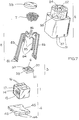
- the contact surfaces 16 can also be connected to the circuit 3 directional upper side of the capacitor arrangement 1, as in FIG. 7 shown so that the capacitor arrangement 1 also through contact zones 34 (see FIG. 8, comparable to those from FIG. 4) on the underside of the Circuit 3 is connected directly to the circuit 3, so that the in 6, 7 and 9 provided insert parts 85 can be omitted.
- These contact zones 34 on the underside of the circuit 3 could have vias comparable to those with reference numeral 32 from FIG.
- the upper housing part 5 is closed by a lower housing part 4, wherein the joining elements 44, 51 engage in one another and both housing parts 4, 5 lock together.
- a separation 55 from the Receiving chamber 57 is the propellant charge chamber 52 with the Propellant charge 7, the partition 55 in the area of Ignition layer 6 has an opening 56 through which the ignition layer 6 Can ignite propellant charge 7.
- the propellant charge chamber 52 in turn has an outflow opening 54 initially closed by a pressure cover 53 For example, to a gas generator of an airbag, which is no longer shown.
- the Compactness of the ignition system is in turn based on the basic one Arrangement of the components, in particular the circuit 3 directly on the Capacitor arrangement 1.
- the insert parts 83, 85 are preferably stamped in one piece from metal strip as well as bent into the appropriate shape and in the material of the upper housing part 5 fixed by extrusion coating, contact areas at the ends of the insert parts 81,82,84,86 remain free.
- an end is in Exterior of the housing, where it is formed as insulation displacement contacts 81 in Fig. 6,7 for the direct contacting of an insulated cable or as plug contacts 82 in Fig. 8,9 for contacting one not closer shown connector.
- the inserts 85 are shown in FIG Capacitor arrangement 1 with on the electrical contact surfaces 16 of the housing capacitor arrangement facing contacts 84 provided. These inserts 85 are in Fig. 8 by the direct electrical contact Contact zones 34 of the circuit 3 with the contact surfaces 16 of the Capacitor arrangement 1 replaced.
- the other ends 86 of the inserts 83 and 85 each contact the Circuit 3.
- the special shape of the inner Contact ends 86 and 84 because these are preferably from the housing protruding resiliently formed so that when inserting the Capacitor arrangement 1 with the circuit 3 arranged thereon in the Upper housing part 5 and closing the housing by the lower housing part 4, the capacitor arrangement 1 with the circuit 3 arranged thereon against the contact ends 86 and 84 of the inserts 83, 85. In addition to mechanical fixation, it also becomes a more secure electrical one Contact guaranteed.
- FIGS. 8 and 9 also have a contact film 36 as a special feature, for example with a local application of conductive adhesive, the contact foil 36 applied to the circuit 3, the contact between this and the inner contact ends 86 and 84 of the inserts 83, 85 improved.
- This contact foil 36 either carries an ignition layer 6 itself, as in FIG. 8, or has a recess for the ignition layer 6 underneath, as shown in FIG. 9.
- the ignition layer 6 can fundamentally both on the circuit 3 and can also be arranged on the capacitor arrangement 1, as already shown in FIG Embodiments in Figures 4 and 5 was explained.
- the inserts 83, 85 can also be fastened to the inside of the housing or formed by metallized tracks on the surface of the Receiving chamber 57 may be formed.
- the housing parts 4 and 5 are preferably pressure-tight with one another and moisture-proof bonded.
- the lower housing part 4 in FIGS. 6 and 7 has recesses 45 for carrying out the inserts 85 and will then filled for example by a casting compound for sealing.
- the partition 55 can be made in one piece from the Housing upper part 5 may be formed, which, for example, by temperature-resistant Plastic injection molding can be produced.
- the partition 55 serves the Protection of the circuit 3 against the effects of temperature and pressure at the explosive combustion of the propellant charge 7.
- the partition 55 is only through an opening 56 is interrupted directly above the ignition layer 6 so that the Ignition layer 6 can ignite the propellant charge 7.
Abstract
Description
Die Erfindung betrifft ein pyrotechnisches Zündsystem mit integrierter
Zündschaltung gemäß dem Oberbegriff des Anspruchs 1.The invention relates to a pyrotechnic ignition system with an integrated
Ignition circuit according to the preamble of
Pyrotechnische Zündsysteme dienen insbesondere zur Auslösung von Insassenrückhalteeinrichtungen, können aber grundsätzlich auch auf militärischem Gebiet oder im Bergbau eingesetzt werden. Durch Freisetzung von Energie durch den Zünder wird eine pyrotechnische Treibladung angezündet. Die Energie wird dabei elektrisch in Form einer Zündspannung zugeführt, die durch elektrische Bauelemente erzeugt und/oder gespeichert wird.Pyrotechnic ignition systems are used in particular to trigger occupant restraint systems, can in principle also in the military field or used in mining. By releasing energy through the A pyrotechnic propellant charge is ignited. The energy will thereby supplied electrically in the form of an ignition voltage, which by electrical Components are generated and / or saved.
Ein solches Zündsystem ist bspw. aus der DE 37 17 149 C3 bekannt und wird dort als Sprengzünder-Zündelement bezeichnet. Auch in diesem Fall werden elektrische Bauelemente, insbesondere ein elektronischer Schaltkreis eingesetzt, der eine Überspannungsschutzeinrichtung, eine Kommunikationseinrichtung, ein Zeitgeber- und Sperrschaltkreis sowie ein Selbsttestmodul enthält. Zur Energiespeicherung dient ein Zündkondensator, der aufgrund seiner großen Größe nicht in den Schaltkreis integriert ist, sondern als ein getrenntes Bauteil ausgeführt wird.Such an ignition system is known, for example, from DE 37 17 149 C3 referred to there as the detonator ignition element. In this case too electrical components, in particular an electronic circuit, of a surge protection device, a communication device Includes timer and inhibit circuit and a self-test module. For An ignition capacitor serves to store energy because of its large size Size is not integrated in the circuit, but as a separate component is performed.
Bei Zündsystemen mit integrierten Zündschaltungen ohne Zündkondensator, wie sie beispielsweise dem Artikel von Willis, K: An introduction to semiconductor initiation of electroexplosive devices, in: 2. internat. symposium on sophisticated car occupant safety systems, airbag 2000, Karlsruhe 1994, S. 42-1 bis 42-9 vorgestellt sind, muß die Zündenergie zum Zeitpunkt der Auslösung der im Zündsystem integrierten Schaltung zugeführt werden, wodurch die verfügbare Zündenergie, die Auslösegeschwindigkeit und Auslösesicherheit herabgesetzt ist.In ignition systems with integrated ignition circuits without an ignition capacitor, such as see, for example, the article by Willis, K: An introduction to semiconductor initiation of electro-explosive devices, in: 2nd international symposium on sophisticated car occupant safety systems, airbag 2000, Karlsruhe 1994, pp. 42-1 to 42-9 are, the ignition energy at the time of triggering the im Ignition system integrated circuit are supplied, making the available Ignition energy, the tripping speed and tripping reliability reduced is.
Die Patentanmeldungen DE 198 36 280 und DE 198 36 278 beschreiben ebenfalls eine ansteuerbare Anzündeinheit mit integrierter Elektronik zum Auslösen eines Rückhaltesystems sowie ein pyrotechnisches Anzündelement, wobei dort Gegenstand der Anmeldung die Abschirmung der Schaltung vor den Einflüssen der Explosion ist. Die Schaltung ist dabei jeweils auf einem Leiterplattenträgerelement angeordnet. Patent applications DE 198 36 280 and DE 198 36 278 also describe a controllable ignition unit with integrated electronics for triggering a restraint system and a pyrotechnic igniter, being there Subject of the registration is the shielding of the circuit from the influences the explosion is. The circuit is always on one Printed circuit board support element arranged.
Die DE 3537820 A1 und die DE 196 53 115 A1 stellen jeweils eine Zündeinheit zum Zünden eines pyrotechnischen Treibsatzes vor, bei denen neben einem elektrisch zündbaren Zünder auch ein Zündenergiespeicher sowie eine Verriegelungseinheit gemeinsam auf einem Halbleiterchip integriert ist, wobei die Verriegelungseinheit aufgrund eines Entriegelungssignals die Entladung des Energiespeichers über den Elektrozünder bewirkt. Die Energiespeicherung mittels Halbleiterkondensatoren ist jedoch zumindest für eine Reihe von Zündern nicht ausreichend.DE 3537820 A1 and DE 196 53 115 A1 each represent an ignition unit to ignite a pyrotechnic propellant, in which in addition to a electrically ignitable igniter also an ignition energy storage and a Locking unit is integrated together on a semiconductor chip, the Locking unit discharge due to an unlocking signal Energy storage causes via the electric igniter. Energy storage using semiconductor capacitors is, however, at least for a number of detonators unsatisfactory.
Die Integration elektrischer Bauelementen in ein pyrotechnisches Anzündelement ist auch Gegenstand der DE 196 10 799 C1, wobei dort aus einem Metallband eine Leiterbahnstruktur ausgestanzt und dreidimensional gebogen wird, diese Leiterbahnen mit einem quaderförmigen Trägerkörper umspritzt werden, wobei in Aussparungen im Trägerkörper nachfolgend Bauelemente eingesetzt werden können, die mit den Leiterbahnen verbunden werden. Der großräumige Zündenergiekondensator wird dabei in einem Hohlraum innerhalb des Trägerkörpers platzsparend verstaut. Ebenso ist eine integrierte Schaltung zur Auslösung vorgesehen. Danach wir die Baugruppe durch ein Gehäuse umschlossen. Der Aufwand für die Herstellung eines solchen Anzündelements und die Störanfälligkeit aufgrund der filigranen Bauweise ist enorm.The integration of electrical components in a pyrotechnic igniter is also the subject of DE 196 10 799 C1, where there is a Metal strip punched out a conductor track structure and bent three-dimensionally is overmolded these conductor tracks with a cuboid carrier body be, with components in recesses in the carrier body can be used, which are connected to the conductor tracks. The Large-scale ignition energy capacitor is placed in a cavity inside of the carrier body to save space. There is also an integrated circuit intended for triggering. Then we put the assembly through a housing enclosed. The effort for the production of such an ignition element and the susceptibility to failure due to the filigree construction is enormous.
Die DE 198 46 110 A1 zeigt die Verwendung separater Substrate (7,8) als
Trägerelemente für ein Zündsystem mit elektrischen Bauelementen (9), die auf
den zwei parallel zueinander beabstandet angeordneten Substraten (7 und 8)
beidseitig angeordnet sind (vgl. bspw. Fig. 1 und Sp. 2, Z. 45 ff.). Die auf den
zwei zueinander gerichteten Seiten der Substrate 7 und 8 befindlichen Bauelemente
(9) liegen zwecks platzsparender Bauweise äußerst nah aneinander.
Eine direkte Verbindung dieser zueinander liegenden Bauelemente (9) der
Substrate (7,8) ist jedoch nicht offenbart und würde üblicherweise zu einer
elektrischen Fehlfunktion, bspw. einem Kurzschluss führen.
Die nachveröffentlichte DE 199 45 790 A1 zeigt in der dortigen Figur 4 ebenfalls
ein Zündsystem, in dem beidseitig eines Trägers (Bezugszeichen 64a weist zwar
auf diesen Träger, wird jedoch anderweitig verwandt) angeordnet einen
elektronischen Schaltkreis (66) und einen Kondensator (67) auf.DE 198 46 110 A1 shows the use of separate substrates (7,8) as
Carrier elements for an ignition system with electrical components (9) on
the two substrates (7 and 8) which are spaced apart and parallel to one another
are arranged on both sides (see, for example, Fig. 1 and Col. 2,
Aufgabe der Erfindung ist es, ein weiteres pyrotechnisches Zündsystem mit integrierten Zündschaltung vorzustellen, welches sehr platzsparend und zudem einfach und kostengünstig herstellbar ist. The object of the invention is to use a further pyrotechnic ignition system to introduce integrated ignition circuit, which is very space-saving and also is easy and inexpensive to manufacture.
Diese Aufgabe wird durch die Merkmale des Patentanspruchs 1 gelöst.
Vorteilhafte Weiterbildungen sind den Unteransprüche zu entnehmen.This object is achieved by the features of
Grundgedanke der Erfindung ist es, ein bereits vorgesehenes elektrisches Bauelement mit zumindest einer ebenen, zumindest bereichsweise selbst nichtleitfähigen Außenfläche als Trägerelement für die anderen Bauelemente und die Schaltung zu verwenden und diese dort anzuordnen. Durch diese Lösung entfällt ein sonst üblicherweise in Form einer Leiterplatte vorgesehenes oder in der DE 196 10 799 C1 quaderförmig ausgebildetes zusätzliches Trägerelement, wodurch neben der Materialeinsparung insbesondere auch der Platzbedarf reduziert, die Fertigung vereinfacht und so die Zuverlässigkeit erhöht wird.The basic idea of the invention is to provide an already provided electrical Component with at least one level, at least in some areas itself non-conductive outer surface as a carrier element for the other components and use the circuit and place it there. Through this A solution is not required, which is usually provided in the form of a printed circuit board or in DE 196 10 799 C1 cuboidal additional support element, whereby in addition to the material saving in particular Reduced space requirements, simplified production and thus increased reliability becomes.
Ausgehend davon ergeben sich eine Vielzahl von Weiterbildungen.Based on this, there are a variety of further training courses.
In ganz besonders vorteilhafter Weise eignet sich gerade eine Kondensatoranordnung, beispielsweise die Plattenkondensatoranordnung eines Zündkondensators aufgrund der recht erheblichen Größe und geraden Außenfläche als Trägerelement.A capacitor arrangement is particularly suitable in a particularly advantageous manner, for example the plate capacitor arrangement of an ignition capacitor due to the rather large size and straight outer surface as a carrier element.
So wird betreffend der Anordnung und Ausgestaltung der Leiterbahnstruktur vorgeschlagen, in einfacher Weise durch metallische Einlegeteile im Gehäuse ausgebildet sein oder am Gehäuse oder auf selbst nicht leitenden Außenflächen der Kondensatoranordnung aufgedampft, abgeschieden oder aufgeklebt werden kann.So regarding the arrangement and design of the conductor track structure proposed, in a simple manner by metallic inserts in the housing be formed or on the housing or on non-conductive outer surfaces themselves can be evaporated, deposited or glued onto the capacitor arrangement can.
Die Einlegeteile ermöglichen im Zusammenspiel mit dem Gehäuse ebenfalls eine äußerst kompakte und einfache Bauform und können sowohl für die Verbindung zwischen Kondensatoranordnung und Schaltkreis als auch hin zu äußeren Anschlüssen verwendet werden, wobei die äußeren Anschlüsse in besonders bevorzugter Weiterbildung sogar direkt aus diesen Einlegeteilen ausgeformt sein können.The inserts in combination with the housing also allow one extremely compact and simple design and can be used both for connection between capacitor arrangement and circuit as well as towards the outside Connections are used, with the outer connections in particular preferred training even be formed directly from these inserts can.
Eine Anordnung der Leiterbahnstruktur auf dem Trägerelement ermöglicht die Ausbildung von Kontaktzonen, die in Verbindung mit entsprechenden Kontaktzonen des Schaltkreises stehen. Besonders vorteilhaft ist es, Schaltkreise als Bauelemente in Form von unverpackten Halbleiterchips, sogenannten Nacktchips ohne Gehäuse oder in Flip-Chip-Technik mit ihrer strukturierten und mit Kontaktzonen versehenen Seite nach unten auf die Leitbahnstruktur zu montieren. Die Leiterbahnstruktur kann auch an den Seitenflächen der Kondensatoranordnung zur Zusammenschaltung der einzelnen Kondensatorbeläge genutzt werden oder eine Verbindung zu weiteren Kontaktzonen schaffen, mit denen das Zündsystem über im Inneren des Gehäuses zugeordnete Kontaktelemente mit einer Auslöseelektronik, bspw. einem Zentralgerät eines Insassenschutzsystems verbunden ist.An arrangement of the conductor track structure on the carrier element enables the Formation of contact zones in connection with appropriate Contact zones of the circuit stand. It is particularly advantageous Circuits as components in the form of unpackaged semiconductor chips, so-called naked chips without housing or in flip-chip technology with their structured and with contact zones down to the Assemble interconnect structure. The conductor track structure can also be connected to the Side surfaces of the capacitor arrangement for interconnecting the individual capacitor layers can be used or a connection to others Create contact zones with which the ignition system is located inside the Contact elements associated with the housing with trigger electronics, for example. is connected to a central device of an occupant protection system.
Die Erfindung wird nachfolgend anhand von Ausführungsbeispielen und Figuren näher erläutert.The invention is described below using exemplary embodiments and figures explained in more detail.
Kurze Beschreibung der Figuren:
Figur 1- Explosionsdarstellung von einer Baugruppe mit einer Kondensatoranordnung mit darauf abgeschiedenen Leitbahnen und Bauelementen sowie dem Gehäuse
Figur 2- Oberseite der Kondensatoranordnung sowie die darauf angeordneten Leitbahnen, Schaltkreise und Zündschicht
Figur 3- Unterseite der Kondensatoranordnung mit Kontaktzonen zum Gehäuseunterteil
Figur 4- Schnitt durch eine Ausgestaltung mit Zündschicht auf der Oberfläche des Zündkondensators
Figur 5- Schnitt durch eine Ausgestaltung mit Zündschicht auf der Oberfläche des integrierten Schaltkreises
Figur 6- Pyrotechnisches Zündsystem mit einer Kondensatoranordnung in einem Gehäuse, auf dieser montiert ein Schaltkreis sowie mit einem Gehäuse mit eingespritzten Einlegeteilen skizzenhaft teilweise aufgeschnitten
Figur 7- Explosionsdarstellung der Ausgestaltung gemäß der
Figur 6 Figur 8- Explosionsdarstellung einer weiteren Ausgestaltung ebenfalls mit einer durch Einlegeteile gebildeten Leiterbahnstruktur
- Figur 9
- skizzenhafte Darstellung einer komplettierten Baugruppe mit Steckerkontaktbereich mit Visualisierung des darin angeordneten pyrotechnischen Zündsystems
- Figure 1
- Exploded view of an assembly with a capacitor arrangement with interconnects and components deposited thereon and the housing
- Figure 2
- Top of the capacitor arrangement and the interconnects, circuits and ignition layer arranged thereon
- Figure 3
- Bottom of the capacitor arrangement with contact zones to the lower part of the housing
- Figure 4
- Section through an embodiment with an ignition layer on the surface of the ignition capacitor
- Figure 5
- Section through an embodiment with an ignition layer on the surface of the integrated circuit
- Figure 6
- Pyrotechnic ignition system with a capacitor arrangement in a housing, on which a circuit is mounted and with a housing with injected inserts, partially cut open in a sketch
- Figure 7
- Exploded view of the configuration according to FIG. 6
- Figure 8
- Exploded view of a further embodiment also with a conductor track structure formed by insert parts
- Figure 9
- Sketchy representation of a completed assembly with plug contact area with visualization of the pyrotechnic ignition system arranged therein
Jede der in den Figuren gezeigten Ausgestaltungen weist grundsätzlich folgende
Grundkomponenten auf, eine Kondensatoranordnung 1, insbesondere einen
Zündkondensator, eine Leiterbahnstruktur 2, Bauelemente, insbesondere einen
Schaltkreis 3, ein Gehäuseunterteil 4, ein Gehäuseoberteil 5, eine Zündschicht 6
sowie eine Treibladung 7. Die Grundkomponenten wurden in allen Figuren mit
den gleichen Bezugszeichen versehen und Details dieser Grundkomponenten im
allgemeinen durch Ergänzung einer weiteren Ziffer bezeichnet.Each of the configurations shown in the figures basically has the following
Basic components, a
Die Figur 1 zeigt zerlegt ein pyrotechnisches Zündsystem, wie es bspw. für den
Einsatz in Gasgeneratoren von Insassenschutzsystemen vorgesehen ist. Das
pyrotechnische Zündsystem besteht aus einer Zündschaltung bestehend aus
einer Kondensatoranordnung 1, insbesondere dem Zündkondensator,
Leitbahnen 2, einem Schaltkreis 3 und einer Zündschicht 6, an der durch
Einprägen von elektrischer Energie ein Anzünden der separat dargestellten
Treibladung 7 des Anzünders bewirkt wird.FIG. 1 shows a pyrotechnic ignition system disassembled, such as for the
Use in gas generators by occupant protection systems is provided. The
pyrotechnic ignition system consists of an ignition circuit consisting of
a
Als Trägerelement für die Zündschaltung dient die Kondensatoranordnung 1 mit
wenigstens einer der ebenen, selbst nicht leitfähigen Außenflächen 11,12,13,
wobei in diesem Ausführungsbeispiel neben den Bauelementen auch die
Leiterbahnstruktur 2 auf den Außenfläche(n) 11,12,13 angeordnet ist. Es wird
gerade die Kondensatoranordnung 1 als Trägerelement verwendet, da gerade
diese üblicherweise ebene, nicht leitfähige Außenflächen 11,12,13 und die
größten Abmaße aller Bauelemente aufweist. Zudem wird eine solche
Kondensatoranordnung 1 häufig aus dielektrischen Material, bspw. Keramik -
Plattenkondensator ausgeführt, auf dem besonders einfach die Leitbahnen 2 in
bekannter Dick- oder Dünnfilmtechnik oder auch durch Aufdampfen aufgebracht
werden können.The
Indem die Kondensatoranordnung 1 bestehend zumindest aus dem
Zündkondensator als Trägerelement für die anderen Bauelemente 3 und die
Leitbahnen 2 verwendet wird, entsteht eine äußerst kompakte und kleine
Baugruppe, wie Figur 1 bereits erkennen läßt.By the
Dieses Zündsystem wird von einem zweiteiligen Gehäuse 4,5 umschlossen,
wobei das Gehäuseunterteil 4 neben Fügehilfselementen 44 mit dem Gehäuseoberteil
5 eine Aufnahmekammer 41 für die Baugruppe und in diesem
Ausführungsbeispiel kontaktzungenförmige Kontaktelemente 42 aufweist, über
die das Zündsystem mit einem Anschlußkabel 43 verbindbar ist. Dazu weist die
Kondensatoranordnung 1 auf der Unterseite 12 Kontaktzonen 26 auf, die in Figur
3 gezeigt werden. Hervorzuheben ist, daß die Kontaktelemente 42 damit direkt
die aus der Leiterbahnstruktur ausgeformten Kontaktzonen 26 kontaktieren, es
also keiner Stecker-Buchsen-Verbindungen oder ähnliches bedarf. Die
Kontaktelemente 42 werden dabei druckdicht im Gehäuseunterteil 4
eingeschweißt bzw. von diesem umspritzt. Bevorzugt ist auch, daß das
Zündsystem vom Gehäuse 4,5 druckdicht umschlossen wird, indem es
maßgenau in die Aufnahmekammer 41,57 des Gehäuses 4,5 eingefügt und dort
vorzugsweise durch Schweiß-, Löt- , Preß- , Crimp- oder Klebverbindungen
arretiert wird. Die Druckdichtheit schützt einerseits das Zündsystem vor äußeren
Einflüssen, insbesondere Feuchtigkeit und ermöglicht zudem beim Zünden einen
Druckaufbau, der sich dann gezielt durch eine von einer Druckmembran 53
zunächst verschlossene Ausströmöffnung 54 im Gehäuseoberteil 5 entlädt.This ignition system is enclosed in a two-part housing 4.5,
the
Die Ausführungsbeispiele in den Figuren 1bis 5 weisen Leitbahnen 21 auf der
Kondensatoranordnung 1 auf, die in diesem Ausführungsbeispiel sowohl die
weiteren Bauelemente 3 untereinander und mit der Kondensatoranordnung 1
sowie mit Anschlüssen 24 für die Zündschicht 6 verbinden, sowie zudem
Leitbahnen 28, die an den Seitenflächen 13 der Kondensatoranordnung 1 angeordnet
sind, wie in Figur 2 und 3 zu sehen ist. Diese verbinden elektrisch die
auf der Oberseite 11 angeordneten Elemente, also Leitbahnen 21, Bauelemente
3 und Zündschicht 6 mit Kontaktzonen 26 auf der Unterseite 12 der
Kondensatoranordnung 1.The exemplary embodiments in FIGS. 1 to 5 have
Als Bauelemente ist in den Figur 1 bis 5 vereinfachend jeweils nur ein Schaltkreis
3 dargestellt. Jedoch können durchaus auch mehrere Schaltkreise und andere
Bauelemente, bspw. Widerstände oder ähnliches so auf der Kondensatoranordnung
1 angeordnet werden.In FIGS. 1 to 5, only one circuit is simplified as a
Die Gehäuseoberseite 5 weist den Fügehilfselementen 44 der Gehäuseunterseite
4 zugeordnete Fügehilfselemente 51 (hier bspw. ausgebildet als Rasthaken
und Rastöffnungen) sowie zudem eine Treibladungskammer 52 auf, in der die
Treibladung 7 des Zündsystems angeordnet ist. Die Treibladungskammer 52
weist eine durch eine Druckmembran 53 zunächst verschlossene
Ausströmöffnung 54 auf. Wird die Zündschicht 6 aktiviert und entzündet diese
die pyrotechnische Treibladung 7, so baut sich innerhalb der
Treibladungskammer 52 ein Druck auf, der die Druckmembran 53 aufreißt und
heiße brennende Treibladungspartikel schlagartig und mit Druck durch die
Ausströmöffnung 54 in den Gasgenerator strömen, wodurch dort eine natürlich
deutlich größere und auf die Gaserzeugung optimierte Treibladung gezündet
wird. Die Treibladungskammer 52 ist vorzugsweise von der Aufnahmekammer
41 für die Kondensatoranordnung 1 mit den Bauelementen durch eine
Abtrennung 55 (siehe insb. Fig. 9) geschützt, die nur im Bereich der Zündschicht
6 eine Öffnung 56 aufweist.The
Für einen Teil der Anwendungsgebiete dieser Zündsysteme sollen
Kommunikationsschaltungen mit in das Gehäuse 4,5 integriert werden. Dazu
können diese entweder auf der von der Zündschicht 6 und Treibladung 7
abgewandten Unterseite 12 der Kondensatoranordnung 1 angeordnet werden
oder entsprechend für diese ja extrem kurze Zeitspanne ausreichend
hitzebeständige Bauelemente und elektrische Verbindungen verwendet werden.
In Figur 1 könnte bspw. in den IC 3 bereits eine solche Kommunikationsschaltung
mit integriert sein, indem der IC 3 ausreichend geschützt bzw. druck - und
hitzebeständig ist. Ein weitgehender Schutz der Schaltung ist schon durch
die weitgehende Abtrennung 55 zwischen der Zündkammer 52 und der
Aufnahmekammer 57/42 für die Kondensatoranordnung 1 möglich, wie dies in
Zusammenhang mit nachfolgenden Figuren noch näher gezeigt wird.For some of the areas of application of these ignition systems
Communication circuits can be integrated into the housing 4.5. To
can either on the
Zudem ist in Figur 2 die Oberseite 11 des Zündkondensators 1 mit den
Kontaktzonen 27 dargestellt, auf die der IC 3 bspw. mittels Flip-Chip-Technik
aufgesetzt wird.In addition, the top 11 of the
Die seitlich an der Kondensatoranordnung 1 verlaufenden Leitbahnen 28 sind in
besonders bevorzugter Weise auch untereinander durch Funkenbrückenspitzen
22 gegen elektrostatische Entladungen geschützt, wie in Figur 2 und 3 zu
erkennen ist. Die Leitbahnen 28 dienen des weiteren zur Verschaltung der
einzelnen Kondensatorbeläge der Kondensatoranordnung 1 zu einem
Kondensator aus mehreren Platten, wie in Figur 4 skizziert ist. Neben der
Energiespeicherung kann die Kondensatoranordnung 1 auch weitere Funktionen
haben, insbesondere als zwei voneinander elektrisch getrennte Kondensatoren
verschaltet werden, von denen einer als Zündkondensator und der andere als
Schutzkondensator gegen ESD, EMV und ähnliche elektrische Störungen
verschaltet ist.The
Die Schnittdarstellung in Figur 4 verdeutlicht noch einmal die Funktion der auf
den Seitenflächen 13 angeordneten Leitbahnen 28 zur Verschaltung der
einzelnen parallelen voneinander durch dielektrisches Material, vorzugsweise
Keramikplatten 14 getrennten Kondensatorplattenbeläge 15 hin zu einer bzw.
auch zwei Kondensatoren.The sectional view in FIG. 4 again illustrates the function of the
the side surfaces 13 arranged
Im Schnitt des IC 3 in Figur 4 bzw. 5 sind die aktive Zone 31, in die die
Transistoren und ähnliches integriert sind, sowie eine Isolationsschicht 33, bspw.
aus Siliziumoxid mit Kontaktzonen 34, bspw. aus aufgedampftem Aluminium,
ausgerichtet entsprechend auf die zugeordneten Kontaktzonen 27 auf der
Kondensatoranordnung 1 skizzenhaft angedeutet.4 and 5 are the
Das Zündmittel ist im Ausführungsbeispiel in Figur 4 als separat auf die Zündbrückenanschlüsse
24 bspw. per Dickfilmtechnik aufzutragende Zündschicht 6
dargestellt, wobei diese Schicht auch einstückig mit den Anschlüssen aus einem
entsprechenden Material, bspw. Widerstandsmaterial, dotiertem Silizium oder
ähnlichem ausgebildet sein kann.In the exemplary embodiment in FIG. 4, the ignition means is separate from the
In dieser Figur wird die Zündbrückenschicht 6 neben dem IC 3 angeordnet und
über Leitbahnen 21 und daraus ausgeformte Anschlüsse 24 mit den anderen
Bauelementen, insbesondere dem IC 3 und der Kondensatoranordnung 1
verbunden.In this figure, the
Alternativ dazu kann die Zündschicht 6 auch im oder auf dem IC 3 angeordnet
werden, wie dies in Figur 5 dargestellt ist. In dieser Figur sind ebenfalls nur
skizzenhaft die halbleitertechnisch strukturierte aktive Schicht 31 sowie die
Isolationsschicht 33 gezeigt, wobei in diesen Querverbindungen 32 von der
Oberseite der aktiven Schicht 31 oder der Isolationsschicht 33 hin zu
Anschlüssen 35 für die Zündschicht 6 auf der bei Face-Down-Montage oben
liegenden Unterseite des IC 3 vorgesehen sind. Gerade in diesem Fall kann aber
auch die Zündschicht 6 in das Substrat des als Nacktchip ausgebildeten IC 3
durch entsprechende Dotierung eingebracht und die Anschlüsse 35 ebenfalls
integriert ausgebildet werden.Alternatively, the
Die Figuren 6 bis 9 zeigen nun weitere Ausgestaltungen, bei denen eine
konventionelle Kondensatoranordnung mit einem eigenen Gehäuse 17
verwendet und die Leiterbahnstruktur 2 durch metallische Einlegeteile 83, 85
gebildet wird.Figures 6 to 9 now show further configurations in which one
conventional capacitor arrangement with its
Gemeinsam mit den vorangegangenen Figuren ist wiederum in einer
Aufnahmekammer des Gehäuses, hier im Gehäuseoberteil 5 ausgebildet und als
57 bezeichnet, die Kondensatoranordnung 1 und auf einer nicht leitfähigen
Außenfläche von diesem der Schaltkreis 3 angeordnet.Together with the previous figures is again in one
Receiving chamber of the housing, here formed in the
Die Kondensatoranordnung 1 ist konventionell, d.h. als handelsüblicher
Kondensator mit einem eigenen Gehäuse 17 ausgebildet. Vorteil dieser Ausgestaltung
ist, daß im Gegensatz zu der mit Leiterbahnstrukturen versehenen
Kondensatoranordnung aus den Figuren 1 bis 5 nun ein sehr preiswerter
Standardkondensator verwendet wird, auf den in gleicher Weise die
Bauelemente, insbesondere der Schaltkreis 3 angeordnet, bspw. aufgeklebt
sind.The
Die Kondensatoranordnung 1 umfaßt in diesem Beispiel nur die Zündkondensatorfunktion
und weist zwei voneinander isolierte elektrische
Kontaktflächen 16 beispielsweise an den Seitenflächen auf, über die die
Kondensatorbeläge im Inneren verschaltet sind. Das Gehäuse 17 der Kondensatoranordnung
1 ist beispielsweise durch eine Umspritzung mit Isolationsmaterial
gebildet. Die Kontaktflächen 16 können auch auf die zum Schaltkreis 3
gerichtete Oberseite der Kondensatoranordnung 1 gezogen sein, wie in Fig. 7
gezeigt, so daß die Kondensatoranordnung 1 auch durch Kontaktzonen 34
(siehe Fig. 8, vergleichbar denen aus Fig. 4) auf der Unterseite des
Schaltkreises 3 direkt mit dem Schaltkreis 3 verbunden ist, so daß die dafür in
Fig. 6, 7 und 9 vorgesehenen Einlegeteile 85 entfallen können. Diese Kontaktzonen
34 auf der Unterseite des Schaltkreises 3 könnten über Durchkontaktierungen
vergleichbar denen mit Bezugszeichen 32 aus Fig. 5 oder durch
am Schaltkreis 3 außen entlang geführte Bahnen mit der Oberseite des Schaltkreises
3 verbunden sein. Stehen die einzelnen Platten der Kondensatoranordnung
senkrecht bezüglich dem Gehäuseunterteil 4, könnte beispielsweise
auch nur diejenige dann zum Schaltkreis 3 zeigende Kontaktfläche 16 über einen
Substratanschluß des Schaltkreises 3, bspw. durch Löten oder Leitkleber,
sowohl mechanisch befestigt als auch elektrisch kontaktiert sein.The
Das Gehäuseoberteil 5 wird durch ein Gehäuseunterteil 4 verschlossen, wobei
die Fügehilfselemente 44, 51 ineinander greifen und beide Gehäuseteile 4, 5
miteinander arretieren. Vorzugsweise durch eine Abtrennung 55 von der
Aufnahmekammer 57 getrennt befindet sich die Treibladungskammer 52 mit der
Treibladung 7, wobei die Abtrennung 55 im Bereich der
Zündschicht 6 eine Öffnung 56 aufweist, durch die die Zündschicht 6 die
Treibladung 7 entzünden kann. Die Treibladungskammer 52 weist wiederum
eine durch einen Druckdeckel 53 zunächst verschlossene Ausströmöffnung 54
bspw. zu einem nicht mehr dargestellten Gasgenerator eines Airbags auf. Die
Kompaktheit des Zündsystems basiert wiederum auf der grundlegenden
Anordnung der Bauelemente, insbesondere des Schaltkreises 3 direkt auf der
Kondensatoranordnung 1.The
Die Einlegeteile 83, 85 sind vorzugsweise einstückig aus Metallband gestanzt
sowie in die entsprechende Form gebogen und im Material des Gehäuseoberteils
5 durch Umspritzen fixiert, wobei an den Enden der Einlegeteile Kontaktbereiche
81,82,84,86 frei bleiben. Für die Einlegeteile 83 wird ein Ende ins
Äußere des Gehäuse geführt, wo er dort ausgebildet ist als Schneid-Klemm-Kontakte
81 in Fig. 6,7 für die direkte Kontaktierung eines isolierten Kabels oder
als Steckkontakte 82 in Fig. 8,9 für die Kontaktierung mit einem nicht näher
gezeigten Stecker. Des weiteren sind in Fig. 9 die Einlegeteile 85 zur
Kondensatoranordnung 1 mit auf die elektrischen Kontaktflächen 16 der
gehäusten Kondensatoranordnung hin gerichteten Kontakten 84 vorgesehen.
Diese Einlegeteile 85 sind in Fig. 8 durch den direkten elektrischen Kontakt der
Kontaktzonen 34 des Schaltkreises 3 mit den Kontaktflächen 16 der
Kondensatoranordnung 1 ersetzt.The
Die anderen Enden 86 der Einlegeteile 83 und 85 kontaktieren jeweils den
Schaltkreis 3. Hervorzuheben ist auch die besondere Ausformung der inneren
Kontaktenden 86 und 84, denn diese sind vorzugsweise aus dem Gehäuse
federelastisch hervorstehend ausgebildet, so daß beim Einführen der
Kondensatoranordnung 1 mit dem darauf angeordneten Schaltkreis 3 in das
Gehäuseoberteil 5 und Verschließen des Gehäuses durch das Gehäuseunterteil
4, die Kondensatoranordnung 1 mit dem darauf angeordneten Schaltkreis 3
gegen die Kontaktenden 86 und 84 der Einlegeteile 83,85 gedrückt werden.
Neben einer mechanischen Fixierung wird so auch ein sicherer elektrischer
Kontakt gewährleistet. Neben einer anderen Ausgestaltung der äußeren
Kontaktenden als Pins 82 in einem Steckerbereich 58 des Gehäuseoberteils 5
weisen die Figuren 8 und 9 als Besonderheit noch eine Kontaktfolie 36 auf,
beispielsweise mit einem lokalen Auftrag von Leitkleber, wobei die Kontaktfolie
36 auf den Schaltkreis 3 aufgebracht den Kontakt zwischen diesem und den
inneren Kontaktenden 86 und 84 der Einlegeteile 83, 85 verbessert.The other ends 86 of the
Diese Kontaktfolie 36 trägt entweder selbst eine Zündschicht 6 , wie in Fig. 8,
oder weist eine Aussparung für die darunter liegende Zündschicht 6, wie in Fig.
9.This
Die Zündschicht 6 kann dabei grundsätzlich sowohl auf dem Schaltkreis 3 als
auch auf der Kondensatoranordnung 1 angeordnet sein, wie bereits anhand der
Ausführungsbeispiele in den Figuren 4 und 5 erläutert wurde.The
Grundsätzlich können die Einlegeteile 83, 85 auch am Gehäuse innen befestigt
oder durch metallisierte Bahnen ausgebildet auf der Oberfläche der
Aufnahmekammer 57 ausgebildet sein.Basically, the
Die Gehäuseteile 4 und 5 werden vorzugsweise miteinander druckdicht und
feuchtigkeitsundurchlässig verbunden. Das Gehäuseunterteil 4 in Figur 6 und 7
weist dabei Aussparungen 45 zur Durchführung der Einlegeteile 85 auf und wird
zur Abdichtung dann bspw. durch eine Gußmasse aufgefüllt.The
Besonders gut zu erkennen ist in Figur 9 auch die Abtrennung 55 zwischen der
Treibladungskammer 52 und der Aufnahmekammer 57 für die Kondensatoranordnung
1 mit dem Schaltkreis 3. Die Abtrennung 55 kann einstückig aus dem
Gehäuseoberteil 5 ausgebildet sein, welches bspw. durch temperaturbeständigen
Kunststoffspritzguß herstellbar ist. Die Abtrennung 55 dient dem
Schutz des Schaltkreises 3 gegen die Temperatur- und Druckeinwirkung bei dem
explosionshaften Abbrand der Treibladung 7. die Abtrennung 55 ist nur durch
eine Öffnung 56 direkt über der Zündschicht 6 unterbrochen, damit die
Zündschicht 6 die Treibladung 7 zünden kann. The
- 11
- KondensatoranordnungCapacitor arrangement
- 1111
-
Oberseite der Kondensatoranordnung 1Top side of the
capacitor arrangement 1 - 1212th
-
Unterseite der Kondensatoranordnung 1Bottom side of the
capacitor arrangement 1 - 1313
-
Seitenflache der Kondensatoranordnung 1Side surface of the
capacitor arrangement 1 - 1414
- IsolationsplattenInsulation panels
- 1515
- KondensatorbelägeCapacitor pads
- 1616
-
elektrische Kontaktflächen eines konventionellen Kondensators 1electrical contact surfaces of a
conventional capacitor 1 - 1717th
-
Gehäuse/Isolationsumspritzung des Kondensators 1Housing / insulation encapsulation of the
capacitor 1 - 22nd
- Leitbahnstruktur, aufgedampft auf der KondensatoranordnungConductor structure, evaporated on the capacitor arrangement
- 2121
- elektrische Leitbahnen zwischen den Bauelementenelectrical interconnects between the components
- 2222
- ESD-BrückenspitzenESD bridge tips
- 2323
- --------
- 2424th
- Zündbrückenanschlüsse ausgeformt aus der Leiterbahnstruktur auf der KondensatoranordnungIgnition bridge connections formed from the conductor structure on the Capacitor arrangement
- 2525th
- --------
- 2626
-
Kontaktzonen
zu den Kontaktzungen 42 im Gehäuseunterteil 4Contact zones
to the
contact tongues 42 in thelower housing part 4 - 2727
-
Kontaktzonen zum IC 3Contact zones to the
IC 3 - 2828
- seitliche Leitbahnenlateral guideways
- 33rd
-
integrierter Schaltkreis als Bauelement auf der Kondensatoranordnung 1Integrated circuit as a component on the
capacitor arrangement 1 - 3131
- aktive Schicht des ICactive layer of the IC
- 3232
-
Durchkontaktierung von der Unterseite auf die Oberseite des IC 3Vias from the bottom to the top of the
IC 3 - 3333
-
Isolationsschicht mit Verbindungen zu den Kontaktzonen 34Insulation layer with connections to the
contact zones 34 - 3434
-
Kontaktzonen des IC 3 zu den Kontaktzonen 27 der Kondensatoranordnung 1Contact zones of the
IC 3 to thecontact zones 27 of thecapacitor arrangement 1 - 3535
-
Anschlüsse für die Zündbrücke 6 auf dem IC 3Connections for the
ignition bridge 6 on theIC 3 - 3636
-
Kontaktfolie zwischen IC 3 und den Einlegeteilen 83, 85Contact film between
IC 3 and theinserts - 3737
-
Kontaktzonen des IC 3 zu den EinlegeteilenContact zones of the
IC 3 to the inserts - 44th
- GehäuseunterteilLower part of the housing
- 4141
-
Aufnahmekammer im Gehäuseunterteil 4 für Kondensatoranordnung 1 und Bauelemente
3Receiving chamber in the
lower housing part 4 forcapacitor arrangement 1 and components 3rd - 4242
-
Kontaktzungen im Gehäuseunterteil 4 zu den Kontaktzonen 26 auf der Unterseite
12 der Kondensatoranordnung 1Contact tongues in the
lower housing part 4 to thecontact zones 26 on theunderside 12 of thecapacitor arrangement 1 - 4343
- Verbindungskabelconnection cable
- 4444
- Rastelemente am GehäuseunterteilLocking elements on the lower part of the housing
- 4545
-
Aussparung im Gehäuseunterteil zur Durchführung der Einlegeteile 83 Recess in the lower housing part for the implementation of the
insert parts 83 - 55
- GehäuseoberteilUpper part of the housing
- 5151
- Rastelemente am GehäuseoberteilLocking elements on the upper part of the housing
- 5252
- TreibladungszündkammerPropellant charge ignition chamber
- 5353
- DruckmembranPressure membrane
- 5454
- Ausströmöffnung zum GasgeneratorOutflow opening to the gas generator
- 5555
- Abtrennung zwischen Zündkammer und Aufnahmekammer für Kondensatoranordnung und ICSeparation between ignition chamber and receiving chamber for capacitor arrangement and IC
- 5656
-
Öffnung in der Abtrennung 55 der Kammern 52/57 Ober der Zündschicht 6Opening in the
partition 55 of thechambers 52/57 above theignition layer 6 - 5757
-
Aufnahmekammer für Kondensatoranordnung 1 und Bauelemente 3 im
Gehäuseoberteil 5Receiving chamber for
capacitor arrangement 1 andcomponents 3 inUpper housing part 5 - 5858
-
Steckerbereich, ausgeformt aus dem Gehäuseoberteil 5Plug area, formed from the
upper housing part 5 - 66
- ZündschichtIgnition layer
- 77
- Treibladung des AnzündersPropellant charge
- 88th
- Einlegeteile als LeitbahnstrukturInserts as a guideway structure
- 8181
- Schneid-Klemm-Anschlüsse für äußere KabelInsulation displacement connections for outer cables
- 8282
- stiftförmig ausgeformte Anschlüsse (Pins) für einen Steckerpin-shaped connections (pins) for a plug
- 8383
-
metallische Einlegeteile mit ausgeformten äußeren Anschlüssen 81,82metallic inserts with molded
outer connections - 8484
-
innere Kontaktenden zur den Kontaktflächen 16 der Kondensatoranordnung 1inner contact ends to the contact surfaces 16 of the
capacitor arrangement 1 - 8585
-
metallische Einlegeteile im Gehäuse 5 mit Kontaktenden 84 zur Kondensatoranordnung
1metallic inserts in the
housing 5 with contact ends 84 for thecapacitor arrangement 1 - 8686
-
federelastisch hervorstehende Kontaktenden zum Schaltkreis 3springy protruding contact ends to the
circuit 3
Claims (28)
Applications Claiming Priority (4)
| Application Number | Priority Date | Filing Date | Title |
|---|---|---|---|
| DE1999140200 DE19940200A1 (en) | 1999-08-25 | 1999-08-25 | Pyrotechnical ignition system with integrated ignition circuit has component with flat outer surface(s) that is non-conducting in at least some areas acting as bearer for other components |
| DE19940200 | 1999-08-25 | ||
| DE19940201 | 1999-08-25 | ||
| DE19940201A DE19940201C1 (en) | 1999-08-25 | 1999-08-25 | Pyrotechnical ignition system with integrated ignition circuit has component with flat outer surface(s) that is non-conducting in at least some areas acting as bearer for other components |
Publications (3)
| Publication Number | Publication Date |
|---|---|
| EP1078825A2 true EP1078825A2 (en) | 2001-02-28 |
| EP1078825A3 EP1078825A3 (en) | 2003-03-26 |
| EP1078825B1 EP1078825B1 (en) | 2007-08-01 |
Family
ID=26054709
Family Applications (1)
| Application Number | Title | Priority Date | Filing Date |
|---|---|---|---|
| EP00117419A Expired - Lifetime EP1078825B1 (en) | 1999-08-25 | 2000-08-11 | Pyrotechnic ignition device with integrated ignition circuit |
Country Status (3)
| Country | Link |
|---|---|
| US (1) | US6591754B1 (en) |
| EP (1) | EP1078825B1 (en) |
| DE (1) | DE50014523D1 (en) |
Cited By (2)
| Publication number | Priority date | Publication date | Assignee | Title |
|---|---|---|---|---|
| EP2093533A1 (en) * | 2006-12-01 | 2009-08-26 | Nipponkayaku Kabushikikaisha | Header assembly, squib, airbag gas generating device, and seatbelt pretentioner gas generating device |
| EP2093534A1 (en) * | 2006-12-01 | 2009-08-26 | Nippon Kayaku Kabushiki Kaisha | Ignition element mounting condenser, header assembly, squib, airbag gas generating device, and seatbelt pretentioner gas generating device |
Families Citing this family (10)
| Publication number | Priority date | Publication date | Assignee | Title |
|---|---|---|---|---|
| DE10236376A1 (en) * | 2002-08-02 | 2004-02-26 | Infineon Technologies Ag | Carrier for optoelectronic components and optical transmission device and optical reception device |
| US7236345B1 (en) | 2003-12-04 | 2007-06-26 | Sandia Corporation | Compact monolithic capacitive discharge unit |
| US7690303B2 (en) * | 2004-04-22 | 2010-04-06 | Reynolds Systems, Inc. | Plastic encapsulated energetic material initiation device |
| US8100043B1 (en) | 2008-03-28 | 2012-01-24 | Reynolds Systems, Inc. | Detonator cartridge and methods of use |
| US8276516B1 (en) | 2008-10-30 | 2012-10-02 | Reynolds Systems, Inc. | Apparatus for detonating a triaminotrinitrobenzene charge |
| US8485097B1 (en) | 2010-06-11 | 2013-07-16 | Reynolds Systems, Inc. | Energetic material initiation device |
| DE102011018248B3 (en) * | 2011-04-19 | 2012-03-29 | Rheinmetall Air Defence Ag | Device and method for programming a projectile |
| US9939235B2 (en) * | 2013-10-09 | 2018-04-10 | Battelle Energy Alliance, Llc | Initiation devices, initiation systems including initiation devices and related methods |
| DE102017110722B4 (en) | 2017-05-17 | 2021-03-18 | Semikron Elektronik Gmbh & Co. Kg | Power electronic arrangement and electric vehicle herewith |
| US11927431B1 (en) * | 2018-12-11 | 2024-03-12 | Northrop Grumman Systems Corporation | Firing switch for compact capacitive discharge unit |
Citations (4)
| Publication number | Priority date | Publication date | Assignee | Title |
|---|---|---|---|---|
| US4819560A (en) * | 1986-05-22 | 1989-04-11 | Detonix Close Corporation | Detonator firing element |
| EP0555651A1 (en) * | 1987-02-16 | 1993-08-18 | Nitro Nobel Ab | Detonator |
| DE19610799C1 (en) * | 1996-03-19 | 1997-09-04 | Siemens Ag | Ignition device for triggering a restraint in a motor vehicle |
| US5889228A (en) * | 1997-04-09 | 1999-03-30 | The Ensign-Bickford Company | Detonator with loosely packed ignition charge and method of assembly |
Family Cites Families (13)
| Publication number | Priority date | Publication date | Assignee | Title |
|---|---|---|---|---|
| DE3537820A1 (en) | 1985-10-24 | 1987-04-30 | Dynamit Nobel Ag | Electronic fuze |
| US5029529A (en) * | 1989-09-25 | 1991-07-09 | Olin Corporation | Semiconductor bridge (SCB) packaging system |
| US5200574A (en) * | 1991-04-05 | 1993-04-06 | Morton International, Inc. | Universal squib connector |
| DE4140692A1 (en) * | 1991-12-10 | 1993-06-17 | Trw Repa Gmbh | ELECTRICAL CONNECTING TO A PYROTECHNICAL GAS GENERATOR PROVIDED WITH ELECTRICAL IGNITION |
| DE4435319A1 (en) * | 1994-10-01 | 1996-04-04 | Temic Bayern Chem Airbag Gmbh | Ignition unit for a gas generator of a passive restraint system |
| US5847309A (en) * | 1995-08-24 | 1998-12-08 | Auburn University | Radio frequency and electrostatic discharge insensitive electro-explosive devices having non-linear resistances |
| DE19653115B4 (en) | 1996-12-19 | 2005-06-02 | Autoliv Development Ab | Ignition unit for a vehicle safety device |
| US6070531A (en) * | 1997-07-22 | 2000-06-06 | Autoliv Asp, Inc. | Application specific integrated circuit package and initiator employing same |
| DE19756563C1 (en) * | 1997-12-18 | 1999-08-19 | Siemens Ag | Integrated circuit arrangement for heating ignition material and using such an integrated circuit arrangement |
| DE19836278C2 (en) | 1998-08-11 | 2000-07-20 | Dynamit Nobel Ag | Externally controllable ignition unit with integrated electronics for triggering a restraint system |
| DE19846110A1 (en) | 1998-10-07 | 2000-04-20 | Bosch Gmbh Robert | Ignition device for restraint devices in a vehicle |
| DE19945790A1 (en) | 1998-10-29 | 2000-05-04 | Dynamit Nobel Ag | Ignition device for igniters which can be triggered by radio and method for triggering these igniters |
| FR2790078B1 (en) * | 1999-02-18 | 2004-11-26 | Livbag Snc | ELECTROPYROTECHNIC IGNITER WITH ENHANCED IGNITION SAFETY |
-
2000
- 2000-08-11 DE DE50014523T patent/DE50014523D1/en not_active Expired - Fee Related
- 2000-08-11 EP EP00117419A patent/EP1078825B1/en not_active Expired - Lifetime
- 2000-08-24 US US09/645,260 patent/US6591754B1/en not_active Expired - Fee Related
Patent Citations (4)
| Publication number | Priority date | Publication date | Assignee | Title |
|---|---|---|---|---|
| US4819560A (en) * | 1986-05-22 | 1989-04-11 | Detonix Close Corporation | Detonator firing element |
| EP0555651A1 (en) * | 1987-02-16 | 1993-08-18 | Nitro Nobel Ab | Detonator |
| DE19610799C1 (en) * | 1996-03-19 | 1997-09-04 | Siemens Ag | Ignition device for triggering a restraint in a motor vehicle |
| US5889228A (en) * | 1997-04-09 | 1999-03-30 | The Ensign-Bickford Company | Detonator with loosely packed ignition charge and method of assembly |
Cited By (4)
| Publication number | Priority date | Publication date | Assignee | Title |
|---|---|---|---|---|
| EP2093533A1 (en) * | 2006-12-01 | 2009-08-26 | Nipponkayaku Kabushikikaisha | Header assembly, squib, airbag gas generating device, and seatbelt pretentioner gas generating device |
| EP2093534A1 (en) * | 2006-12-01 | 2009-08-26 | Nippon Kayaku Kabushiki Kaisha | Ignition element mounting condenser, header assembly, squib, airbag gas generating device, and seatbelt pretentioner gas generating device |
| EP2093533A4 (en) * | 2006-12-01 | 2012-10-31 | Nippon Kayaku Kk | Header assembly, squib, airbag gas generating device, and seatbelt pretentioner gas generating device |
| EP2093534A4 (en) * | 2006-12-01 | 2012-11-07 | Nippon Kayaku Kk | Ignition element mounting condenser, header assembly, squib, airbag gas generating device, and seatbelt pretentioner gas generating device |
Also Published As
| Publication number | Publication date |
|---|---|
| EP1078825A3 (en) | 2003-03-26 |
| DE50014523D1 (en) | 2007-09-13 |
| EP1078825B1 (en) | 2007-08-01 |
| US6591754B1 (en) | 2003-07-15 |
Similar Documents
| Publication | Publication Date | Title |
|---|---|---|
| DE19610799C1 (en) | Ignition device for triggering a restraint in a motor vehicle | |
| DE60124374T2 (en) | Igniter construction with activation circuit | |
| CH635673A5 (en) | ELECTRICAL TOOL. | |
| DE60023818T2 (en) | Anti-electrostatic discharge protected pyrotechnic igniter with photo-etched ignition bridge | |
| EP1078825B1 (en) | Pyrotechnic ignition device with integrated ignition circuit | |
| EP0904613B1 (en) | Connector with a strip connector fitted with electrical components, method for the production thereof | |
| EP1677067B1 (en) | Device for the production of pyrotechnical effects. | |
| CH674570A5 (en) | ||
| DE4218881A1 (en) | IGNITIONER WITH DIGITAL DELAY | |
| DE3003172A1 (en) | PYROTECHNICAL ARRANGEMENT | |
| EP0993589B1 (en) | Igniter | |
| DE19940201C1 (en) | Pyrotechnical ignition system with integrated ignition circuit has component with flat outer surface(s) that is non-conducting in at least some areas acting as bearer for other components | |
| DE19940200A1 (en) | Pyrotechnical ignition system with integrated ignition circuit has component with flat outer surface(s) that is non-conducting in at least some areas acting as bearer for other components | |
| EP1119472B1 (en) | Deployment device for restraint means in a vehicle, with switching elements located in the support means | |
| EP1135281A1 (en) | Ignition device for restraint means in a vehicle | |
| DE10024664C2 (en) | Method for producing an ignition module for triggering a propellant charge, in particular a propellant charge contained in an occupant protection agent, and an ignition module | |
| EP1256776B1 (en) | Pyrotechnic igniting element on a circuit substrate through which it is linked to an electronic igniting component | |
| EP1256774B1 (en) | Pyrotechnic igniter with an incorporated electronic circuit | |
| DE19820757B4 (en) | Squib for an airbag | |
| EP0892999B1 (en) | Electrical switching and control device | |
| EP1101667B1 (en) | Igniter | |
| EP1101668B1 (en) | Igniter | |
| DE10018411B4 (en) | Ignition device for pyrotechnic gas generators | |
| DE19962590A1 (en) | Control module for detonation units for pyrotechnic elements, comprises switch and control unit embedded in plastic member | |
| WO2003104044A1 (en) | Ignition device for the gas generator on an occupant restraint system in a motor vehicle |
Legal Events
| Date | Code | Title | Description |
|---|---|---|---|
| PUAI | Public reference made under article 153(3) epc to a published international application that has entered the european phase |
Free format text: ORIGINAL CODE: 0009012 |
|
| AK | Designated contracting states |
Kind code of ref document: A2 Designated state(s): AT BE CH CY DE DK ES FI FR GB GR IE IT LI LU MC NL PT SE |
|
| AX | Request for extension of the european patent |
Free format text: AL;LT;LV;MK;RO;SI |
|
| RAP1 | Party data changed (applicant data changed or rights of an application transferred) |
Owner name: CONTI TEMIC MICROELECTRONIC GMBH |
|
| PUAL | Search report despatched |
Free format text: ORIGINAL CODE: 0009013 |
|
| AK | Designated contracting states |
Kind code of ref document: A3 Designated state(s): AT BE CH CY DE DK ES FI FR GB GR IE IT LI LU MC NL PT SE |
|
| AX | Request for extension of the european patent |
Extension state: AL LT LV MK RO SI |
|
| 17P | Request for examination filed |
Effective date: 20030920 |
|
| AKX | Designation fees paid |
Designated state(s): DE FR GB SE |
|
| GRAP | Despatch of communication of intention to grant a patent |
Free format text: ORIGINAL CODE: EPIDOSNIGR1 |
|
| GRAS | Grant fee paid |
Free format text: ORIGINAL CODE: EPIDOSNIGR3 |
|
| RAP1 | Party data changed (applicant data changed or rights of an application transferred) |
Owner name: CONTI TEMIC MICROELECTRONIC GMBH Owner name: TRW AIRBAG SYSTEMS GMBH |
|
| GRAA | (expected) grant |
Free format text: ORIGINAL CODE: 0009210 |
|
| AK | Designated contracting states |
Kind code of ref document: B1 Designated state(s): DE FR GB SE |
|
| REG | Reference to a national code |
Ref country code: GB Ref legal event code: FG4D Free format text: NOT ENGLISH |
|
| REF | Corresponds to: |
Ref document number: 50014523 Country of ref document: DE Date of ref document: 20070913 Kind code of ref document: P |
|
| GBV | Gb: ep patent (uk) treated as always having been void in accordance with gb section 77(7)/1977 [no translation filed] |
Effective date: 20070801 |
|
| EN | Fr: translation not filed | ||
| PG25 | Lapsed in a contracting state [announced via postgrant information from national office to epo] |
Ref country code: GB Free format text: LAPSE BECAUSE OF FAILURE TO SUBMIT A TRANSLATION OF THE DESCRIPTION OR TO PAY THE FEE WITHIN THE PRESCRIBED TIME-LIMIT Effective date: 20070801 |
|
| PLBE | No opposition filed within time limit |
Free format text: ORIGINAL CODE: 0009261 |
|
| STAA | Information on the status of an ep patent application or granted ep patent |
Free format text: STATUS: NO OPPOSITION FILED WITHIN TIME LIMIT |
|
| PG25 | Lapsed in a contracting state [announced via postgrant information from national office to epo] |
Ref country code: SE Free format text: LAPSE BECAUSE OF FAILURE TO SUBMIT A TRANSLATION OF THE DESCRIPTION OR TO PAY THE FEE WITHIN THE PRESCRIBED TIME-LIMIT Effective date: 20071101 |
|
| 26N | No opposition filed |
Effective date: 20080506 |
|
| PG25 | Lapsed in a contracting state [announced via postgrant information from national office to epo] |
Ref country code: FR Free format text: LAPSE BECAUSE OF FAILURE TO SUBMIT A TRANSLATION OF THE DESCRIPTION OR TO PAY THE FEE WITHIN THE PRESCRIBED TIME-LIMIT Effective date: 20080328 |
|
| PGFP | Annual fee paid to national office [announced via postgrant information from national office to epo] |
Ref country code: DE Payment date: 20080822 Year of fee payment: 9 |
|
| PG25 | Lapsed in a contracting state [announced via postgrant information from national office to epo] |
Ref country code: DE Free format text: LAPSE BECAUSE OF NON-PAYMENT OF DUE FEES Effective date: 20100302 |