EP1078805A1 - Control of vehicle driveline during vehicle start and drive-off - Google Patents
Control of vehicle driveline during vehicle start and drive-off Download PDFInfo
- Publication number
- EP1078805A1 EP1078805A1 EP99116567A EP99116567A EP1078805A1 EP 1078805 A1 EP1078805 A1 EP 1078805A1 EP 99116567 A EP99116567 A EP 99116567A EP 99116567 A EP99116567 A EP 99116567A EP 1078805 A1 EP1078805 A1 EP 1078805A1
- Authority
- EP
- European Patent Office
- Prior art keywords
- control
- engine
- clutch
- torque
- motor vehicle
- Prior art date
- Legal status (The legal status is an assumption and is not a legal conclusion. Google has not performed a legal analysis and makes no representation as to the accuracy of the status listed.)
- Granted
Links
Images
Classifications
-
- B—PERFORMING OPERATIONS; TRANSPORTING
- B60—VEHICLES IN GENERAL
- B60W—CONJOINT CONTROL OF VEHICLE SUB-UNITS OF DIFFERENT TYPE OR DIFFERENT FUNCTION; CONTROL SYSTEMS SPECIALLY ADAPTED FOR HYBRID VEHICLES; ROAD VEHICLE DRIVE CONTROL SYSTEMS FOR PURPOSES NOT RELATED TO THE CONTROL OF A PARTICULAR SUB-UNIT
- B60W10/00—Conjoint control of vehicle sub-units of different type or different function
- B60W10/04—Conjoint control of vehicle sub-units of different type or different function including control of propulsion units
- B60W10/06—Conjoint control of vehicle sub-units of different type or different function including control of propulsion units including control of combustion engines
-
- B—PERFORMING OPERATIONS; TRANSPORTING
- B60—VEHICLES IN GENERAL
- B60W—CONJOINT CONTROL OF VEHICLE SUB-UNITS OF DIFFERENT TYPE OR DIFFERENT FUNCTION; CONTROL SYSTEMS SPECIALLY ADAPTED FOR HYBRID VEHICLES; ROAD VEHICLE DRIVE CONTROL SYSTEMS FOR PURPOSES NOT RELATED TO THE CONTROL OF A PARTICULAR SUB-UNIT
- B60W30/00—Purposes of road vehicle drive control systems not related to the control of a particular sub-unit, e.g. of systems using conjoint control of vehicle sub-units, or advanced driver assistance systems for ensuring comfort, stability and safety or drive control systems for propelling or retarding the vehicle
- B60W30/18—Propelling the vehicle
- B60W30/188—Controlling power parameters of the driveline, e.g. determining the required power
-
- B—PERFORMING OPERATIONS; TRANSPORTING
- B60—VEHICLES IN GENERAL
- B60W—CONJOINT CONTROL OF VEHICLE SUB-UNITS OF DIFFERENT TYPE OR DIFFERENT FUNCTION; CONTROL SYSTEMS SPECIALLY ADAPTED FOR HYBRID VEHICLES; ROAD VEHICLE DRIVE CONTROL SYSTEMS FOR PURPOSES NOT RELATED TO THE CONTROL OF A PARTICULAR SUB-UNIT
- B60W10/00—Conjoint control of vehicle sub-units of different type or different function
- B60W10/02—Conjoint control of vehicle sub-units of different type or different function including control of driveline clutches
-
- B—PERFORMING OPERATIONS; TRANSPORTING
- B60—VEHICLES IN GENERAL
- B60W—CONJOINT CONTROL OF VEHICLE SUB-UNITS OF DIFFERENT TYPE OR DIFFERENT FUNCTION; CONTROL SYSTEMS SPECIALLY ADAPTED FOR HYBRID VEHICLES; ROAD VEHICLE DRIVE CONTROL SYSTEMS FOR PURPOSES NOT RELATED TO THE CONTROL OF A PARTICULAR SUB-UNIT
- B60W10/00—Conjoint control of vehicle sub-units of different type or different function
- B60W10/10—Conjoint control of vehicle sub-units of different type or different function including control of change-speed gearings
-
- B—PERFORMING OPERATIONS; TRANSPORTING
- B60—VEHICLES IN GENERAL
- B60W—CONJOINT CONTROL OF VEHICLE SUB-UNITS OF DIFFERENT TYPE OR DIFFERENT FUNCTION; CONTROL SYSTEMS SPECIALLY ADAPTED FOR HYBRID VEHICLES; ROAD VEHICLE DRIVE CONTROL SYSTEMS FOR PURPOSES NOT RELATED TO THE CONTROL OF A PARTICULAR SUB-UNIT
- B60W30/00—Purposes of road vehicle drive control systems not related to the control of a particular sub-unit, e.g. of systems using conjoint control of vehicle sub-units, or advanced driver assistance systems for ensuring comfort, stability and safety or drive control systems for propelling or retarding the vehicle
- B60W30/18—Propelling the vehicle
- B60W30/18009—Propelling the vehicle related to particular drive situations
- B60W30/18027—Drive off, accelerating from standstill
-
- B—PERFORMING OPERATIONS; TRANSPORTING
- B60—VEHICLES IN GENERAL
- B60W—CONJOINT CONTROL OF VEHICLE SUB-UNITS OF DIFFERENT TYPE OR DIFFERENT FUNCTION; CONTROL SYSTEMS SPECIALLY ADAPTED FOR HYBRID VEHICLES; ROAD VEHICLE DRIVE CONTROL SYSTEMS FOR PURPOSES NOT RELATED TO THE CONTROL OF A PARTICULAR SUB-UNIT
- B60W30/00—Purposes of road vehicle drive control systems not related to the control of a particular sub-unit, e.g. of systems using conjoint control of vehicle sub-units, or advanced driver assistance systems for ensuring comfort, stability and safety or drive control systems for propelling or retarding the vehicle
- B60W30/18—Propelling the vehicle
- B60W30/18009—Propelling the vehicle related to particular drive situations
- B60W30/18063—Creeping
-
- F—MECHANICAL ENGINEERING; LIGHTING; HEATING; WEAPONS; BLASTING
- F16—ENGINEERING ELEMENTS AND UNITS; GENERAL MEASURES FOR PRODUCING AND MAINTAINING EFFECTIVE FUNCTIONING OF MACHINES OR INSTALLATIONS; THERMAL INSULATION IN GENERAL
- F16D—COUPLINGS FOR TRANSMITTING ROTATION; CLUTCHES; BRAKES
- F16D48/00—External control of clutches
- F16D48/06—Control by electric or electronic means, e.g. of fluid pressure
- F16D48/068—Control by electric or electronic means, e.g. of fluid pressure using signals from a manually actuated gearshift linkage
-
- F—MECHANICAL ENGINEERING; LIGHTING; HEATING; WEAPONS; BLASTING
- F16—ENGINEERING ELEMENTS AND UNITS; GENERAL MEASURES FOR PRODUCING AND MAINTAINING EFFECTIVE FUNCTIONING OF MACHINES OR INSTALLATIONS; THERMAL INSULATION IN GENERAL
- F16D—COUPLINGS FOR TRANSMITTING ROTATION; CLUTCHES; BRAKES
- F16D48/00—External control of clutches
- F16D48/06—Control by electric or electronic means, e.g. of fluid pressure
- F16D48/08—Regulating clutch take-up on starting
-
- F—MECHANICAL ENGINEERING; LIGHTING; HEATING; WEAPONS; BLASTING
- F16—ENGINEERING ELEMENTS AND UNITS; GENERAL MEASURES FOR PRODUCING AND MAINTAINING EFFECTIVE FUNCTIONING OF MACHINES OR INSTALLATIONS; THERMAL INSULATION IN GENERAL
- F16H—GEARING
- F16H61/00—Control functions within control units of change-speed- or reversing-gearings for conveying rotary motion ; Control of exclusively fluid gearing, friction gearing, gearings with endless flexible members or other particular types of gearing
- F16H61/66—Control functions within control units of change-speed- or reversing-gearings for conveying rotary motion ; Control of exclusively fluid gearing, friction gearing, gearings with endless flexible members or other particular types of gearing specially adapted for continuously variable gearings
-
- B—PERFORMING OPERATIONS; TRANSPORTING
- B60—VEHICLES IN GENERAL
- B60W—CONJOINT CONTROL OF VEHICLE SUB-UNITS OF DIFFERENT TYPE OR DIFFERENT FUNCTION; CONTROL SYSTEMS SPECIALLY ADAPTED FOR HYBRID VEHICLES; ROAD VEHICLE DRIVE CONTROL SYSTEMS FOR PURPOSES NOT RELATED TO THE CONTROL OF A PARTICULAR SUB-UNIT
- B60W50/00—Details of control systems for road vehicle drive control not related to the control of a particular sub-unit, e.g. process diagnostic or vehicle driver interfaces
- B60W2050/0001—Details of the control system
- B60W2050/0043—Signal treatments, identification of variables or parameters, parameter estimation or state estimation
- B60W2050/0057—Frequency analysis, spectral techniques or transforms
-
- B—PERFORMING OPERATIONS; TRANSPORTING
- B60—VEHICLES IN GENERAL
- B60W—CONJOINT CONTROL OF VEHICLE SUB-UNITS OF DIFFERENT TYPE OR DIFFERENT FUNCTION; CONTROL SYSTEMS SPECIALLY ADAPTED FOR HYBRID VEHICLES; ROAD VEHICLE DRIVE CONTROL SYSTEMS FOR PURPOSES NOT RELATED TO THE CONTROL OF A PARTICULAR SUB-UNIT
- B60W2530/00—Input parameters relating to vehicle conditions or values, not covered by groups B60W2510/00 or B60W2520/00
-
- B—PERFORMING OPERATIONS; TRANSPORTING
- B60—VEHICLES IN GENERAL
- B60W—CONJOINT CONTROL OF VEHICLE SUB-UNITS OF DIFFERENT TYPE OR DIFFERENT FUNCTION; CONTROL SYSTEMS SPECIALLY ADAPTED FOR HYBRID VEHICLES; ROAD VEHICLE DRIVE CONTROL SYSTEMS FOR PURPOSES NOT RELATED TO THE CONTROL OF A PARTICULAR SUB-UNIT
- B60W2540/00—Input parameters relating to occupants
- B60W2540/30—Driving style
-
- B—PERFORMING OPERATIONS; TRANSPORTING
- B60—VEHICLES IN GENERAL
- B60W—CONJOINT CONTROL OF VEHICLE SUB-UNITS OF DIFFERENT TYPE OR DIFFERENT FUNCTION; CONTROL SYSTEMS SPECIALLY ADAPTED FOR HYBRID VEHICLES; ROAD VEHICLE DRIVE CONTROL SYSTEMS FOR PURPOSES NOT RELATED TO THE CONTROL OF A PARTICULAR SUB-UNIT
- B60W2710/00—Output or target parameters relating to a particular sub-units
- B60W2710/06—Combustion engines, Gas turbines
- B60W2710/0666—Engine torque
-
- B—PERFORMING OPERATIONS; TRANSPORTING
- B60—VEHICLES IN GENERAL
- B60W—CONJOINT CONTROL OF VEHICLE SUB-UNITS OF DIFFERENT TYPE OR DIFFERENT FUNCTION; CONTROL SYSTEMS SPECIALLY ADAPTED FOR HYBRID VEHICLES; ROAD VEHICLE DRIVE CONTROL SYSTEMS FOR PURPOSES NOT RELATED TO THE CONTROL OF A PARTICULAR SUB-UNIT
- B60W2710/00—Output or target parameters relating to a particular sub-units
- B60W2710/10—Change speed gearings
- B60W2710/105—Output torque
-
- B—PERFORMING OPERATIONS; TRANSPORTING
- B60—VEHICLES IN GENERAL
- B60W—CONJOINT CONTROL OF VEHICLE SUB-UNITS OF DIFFERENT TYPE OR DIFFERENT FUNCTION; CONTROL SYSTEMS SPECIALLY ADAPTED FOR HYBRID VEHICLES; ROAD VEHICLE DRIVE CONTROL SYSTEMS FOR PURPOSES NOT RELATED TO THE CONTROL OF A PARTICULAR SUB-UNIT
- B60W40/00—Estimation or calculation of non-directly measurable driving parameters for road vehicle drive control systems not related to the control of a particular sub unit, e.g. by using mathematical models
- B60W40/08—Estimation or calculation of non-directly measurable driving parameters for road vehicle drive control systems not related to the control of a particular sub unit, e.g. by using mathematical models related to drivers or passengers
- B60W40/09—Driving style or behaviour
-
- F—MECHANICAL ENGINEERING; LIGHTING; HEATING; WEAPONS; BLASTING
- F16—ENGINEERING ELEMENTS AND UNITS; GENERAL MEASURES FOR PRODUCING AND MAINTAINING EFFECTIVE FUNCTIONING OF MACHINES OR INSTALLATIONS; THERMAL INSULATION IN GENERAL
- F16D—COUPLINGS FOR TRANSMITTING ROTATION; CLUTCHES; BRAKES
- F16D2500/00—External control of clutches by electric or electronic means
- F16D2500/10—System to be controlled
- F16D2500/104—Clutch
- F16D2500/10443—Clutch type
- F16D2500/10481—Automatic clutch, e.g. centrifugal masses
-
- F—MECHANICAL ENGINEERING; LIGHTING; HEATING; WEAPONS; BLASTING
- F16—ENGINEERING ELEMENTS AND UNITS; GENERAL MEASURES FOR PRODUCING AND MAINTAINING EFFECTIVE FUNCTIONING OF MACHINES OR INSTALLATIONS; THERMAL INSULATION IN GENERAL
- F16D—COUPLINGS FOR TRANSMITTING ROTATION; CLUTCHES; BRAKES
- F16D2500/00—External control of clutches by electric or electronic means
- F16D2500/30—Signal inputs
- F16D2500/304—Signal inputs from the clutch
- F16D2500/30406—Clutch slip
-
- F—MECHANICAL ENGINEERING; LIGHTING; HEATING; WEAPONS; BLASTING
- F16—ENGINEERING ELEMENTS AND UNITS; GENERAL MEASURES FOR PRODUCING AND MAINTAINING EFFECTIVE FUNCTIONING OF MACHINES OR INSTALLATIONS; THERMAL INSULATION IN GENERAL
- F16D—COUPLINGS FOR TRANSMITTING ROTATION; CLUTCHES; BRAKES
- F16D2500/00—External control of clutches by electric or electronic means
- F16D2500/30—Signal inputs
- F16D2500/304—Signal inputs from the clutch
- F16D2500/3042—Signal inputs from the clutch from the output shaft
- F16D2500/30421—Torque of the output shaft
- F16D2500/30425—Estimation of the transmitted clutch torque, e.g. applying dynamic torque balance equation
-
- F—MECHANICAL ENGINEERING; LIGHTING; HEATING; WEAPONS; BLASTING
- F16—ENGINEERING ELEMENTS AND UNITS; GENERAL MEASURES FOR PRODUCING AND MAINTAINING EFFECTIVE FUNCTIONING OF MACHINES OR INSTALLATIONS; THERMAL INSULATION IN GENERAL
- F16D—COUPLINGS FOR TRANSMITTING ROTATION; CLUTCHES; BRAKES
- F16D2500/00—External control of clutches by electric or electronic means
- F16D2500/30—Signal inputs
- F16D2500/312—External to the vehicle
- F16D2500/3124—Driving conditions, e.g. climbing hills, cornering, traffic
-
- F—MECHANICAL ENGINEERING; LIGHTING; HEATING; WEAPONS; BLASTING
- F16—ENGINEERING ELEMENTS AND UNITS; GENERAL MEASURES FOR PRODUCING AND MAINTAINING EFFECTIVE FUNCTIONING OF MACHINES OR INSTALLATIONS; THERMAL INSULATION IN GENERAL
- F16D—COUPLINGS FOR TRANSMITTING ROTATION; CLUTCHES; BRAKES
- F16D2500/00—External control of clutches by electric or electronic means
- F16D2500/30—Signal inputs
- F16D2500/314—Signal inputs from the user
- F16D2500/31406—Signal inputs from the user input from pedals
- F16D2500/3144—Accelerator pedal position
-
- F—MECHANICAL ENGINEERING; LIGHTING; HEATING; WEAPONS; BLASTING
- F16—ENGINEERING ELEMENTS AND UNITS; GENERAL MEASURES FOR PRODUCING AND MAINTAINING EFFECTIVE FUNCTIONING OF MACHINES OR INSTALLATIONS; THERMAL INSULATION IN GENERAL
- F16D—COUPLINGS FOR TRANSMITTING ROTATION; CLUTCHES; BRAKES
- F16D2500/00—External control of clutches by electric or electronic means
- F16D2500/30—Signal inputs
- F16D2500/314—Signal inputs from the user
- F16D2500/31486—Recognition of user style of driving, e.g. sportive, calm, nervous
-
- F—MECHANICAL ENGINEERING; LIGHTING; HEATING; WEAPONS; BLASTING
- F16—ENGINEERING ELEMENTS AND UNITS; GENERAL MEASURES FOR PRODUCING AND MAINTAINING EFFECTIVE FUNCTIONING OF MACHINES OR INSTALLATIONS; THERMAL INSULATION IN GENERAL
- F16D—COUPLINGS FOR TRANSMITTING ROTATION; CLUTCHES; BRAKES
- F16D2500/00—External control of clutches by electric or electronic means
- F16D2500/70—Details about the implementation of the control system
- F16D2500/702—Look-up tables
- F16D2500/70252—Clutch torque
- F16D2500/7027—Engine speed
-
- F—MECHANICAL ENGINEERING; LIGHTING; HEATING; WEAPONS; BLASTING
- F16—ENGINEERING ELEMENTS AND UNITS; GENERAL MEASURES FOR PRODUCING AND MAINTAINING EFFECTIVE FUNCTIONING OF MACHINES OR INSTALLATIONS; THERMAL INSULATION IN GENERAL
- F16D—COUPLINGS FOR TRANSMITTING ROTATION; CLUTCHES; BRAKES
- F16D2500/00—External control of clutches by electric or electronic means
- F16D2500/70—Details about the implementation of the control system
- F16D2500/704—Output parameters from the control unit; Target parameters to be controlled
- F16D2500/70402—Actuator parameters
- F16D2500/7041—Position
-
- F—MECHANICAL ENGINEERING; LIGHTING; HEATING; WEAPONS; BLASTING
- F16—ENGINEERING ELEMENTS AND UNITS; GENERAL MEASURES FOR PRODUCING AND MAINTAINING EFFECTIVE FUNCTIONING OF MACHINES OR INSTALLATIONS; THERMAL INSULATION IN GENERAL
- F16D—COUPLINGS FOR TRANSMITTING ROTATION; CLUTCHES; BRAKES
- F16D2500/00—External control of clutches by electric or electronic means
- F16D2500/70—Details about the implementation of the control system
- F16D2500/704—Output parameters from the control unit; Target parameters to be controlled
- F16D2500/70402—Actuator parameters
- F16D2500/70416—Angle
-
- F—MECHANICAL ENGINEERING; LIGHTING; HEATING; WEAPONS; BLASTING
- F16—ENGINEERING ELEMENTS AND UNITS; GENERAL MEASURES FOR PRODUCING AND MAINTAINING EFFECTIVE FUNCTIONING OF MACHINES OR INSTALLATIONS; THERMAL INSULATION IN GENERAL
- F16D—COUPLINGS FOR TRANSMITTING ROTATION; CLUTCHES; BRAKES
- F16D2500/00—External control of clutches by electric or electronic means
- F16D2500/70—Details about the implementation of the control system
- F16D2500/704—Output parameters from the control unit; Target parameters to be controlled
- F16D2500/70422—Clutch parameters
- F16D2500/70438—From the output shaft
- F16D2500/7044—Output shaft torque
-
- F—MECHANICAL ENGINEERING; LIGHTING; HEATING; WEAPONS; BLASTING
- F16—ENGINEERING ELEMENTS AND UNITS; GENERAL MEASURES FOR PRODUCING AND MAINTAINING EFFECTIVE FUNCTIONING OF MACHINES OR INSTALLATIONS; THERMAL INSULATION IN GENERAL
- F16D—COUPLINGS FOR TRANSMITTING ROTATION; CLUTCHES; BRAKES
- F16D2500/00—External control of clutches by electric or electronic means
- F16D2500/70—Details about the implementation of the control system
- F16D2500/704—Output parameters from the control unit; Target parameters to be controlled
- F16D2500/70452—Engine parameters
- F16D2500/70454—Engine speed
-
- F—MECHANICAL ENGINEERING; LIGHTING; HEATING; WEAPONS; BLASTING
- F16—ENGINEERING ELEMENTS AND UNITS; GENERAL MEASURES FOR PRODUCING AND MAINTAINING EFFECTIVE FUNCTIONING OF MACHINES OR INSTALLATIONS; THERMAL INSULATION IN GENERAL
- F16D—COUPLINGS FOR TRANSMITTING ROTATION; CLUTCHES; BRAKES
- F16D2500/00—External control of clutches by electric or electronic means
- F16D2500/70—Details about the implementation of the control system
- F16D2500/704—Output parameters from the control unit; Target parameters to be controlled
- F16D2500/70452—Engine parameters
- F16D2500/70462—Opening of the throttle valve
-
- F—MECHANICAL ENGINEERING; LIGHTING; HEATING; WEAPONS; BLASTING
- F16—ENGINEERING ELEMENTS AND UNITS; GENERAL MEASURES FOR PRODUCING AND MAINTAINING EFFECTIVE FUNCTIONING OF MACHINES OR INSTALLATIONS; THERMAL INSULATION IN GENERAL
- F16D—COUPLINGS FOR TRANSMITTING ROTATION; CLUTCHES; BRAKES
- F16D2500/00—External control of clutches by electric or electronic means
- F16D2500/70—Details about the implementation of the control system
- F16D2500/704—Output parameters from the control unit; Target parameters to be controlled
- F16D2500/70464—Transmission parameters
- F16D2500/70488—Selection of the gear ratio
-
- F—MECHANICAL ENGINEERING; LIGHTING; HEATING; WEAPONS; BLASTING
- F16—ENGINEERING ELEMENTS AND UNITS; GENERAL MEASURES FOR PRODUCING AND MAINTAINING EFFECTIVE FUNCTIONING OF MACHINES OR INSTALLATIONS; THERMAL INSULATION IN GENERAL
- F16D—COUPLINGS FOR TRANSMITTING ROTATION; CLUTCHES; BRAKES
- F16D2500/00—External control of clutches by electric or electronic means
- F16D2500/70—Details about the implementation of the control system
- F16D2500/706—Strategy of control
- F16D2500/70636—Fuzzy logic
-
- F—MECHANICAL ENGINEERING; LIGHTING; HEATING; WEAPONS; BLASTING
- F16—ENGINEERING ELEMENTS AND UNITS; GENERAL MEASURES FOR PRODUCING AND MAINTAINING EFFECTIVE FUNCTIONING OF MACHINES OR INSTALLATIONS; THERMAL INSULATION IN GENERAL
- F16H—GEARING
- F16H63/00—Control outputs from the control unit to change-speed- or reversing-gearings for conveying rotary motion or to other devices than the final output mechanism
- F16H63/40—Control outputs from the control unit to change-speed- or reversing-gearings for conveying rotary motion or to other devices than the final output mechanism comprising signals other than signals for actuating the final output mechanisms
- F16H63/46—Signals to a clutch outside the gearbox
Landscapes
- Engineering & Computer Science (AREA)
- Mechanical Engineering (AREA)
- General Engineering & Computer Science (AREA)
- Combustion & Propulsion (AREA)
- Transportation (AREA)
- Chemical & Material Sciences (AREA)
- Physics & Mathematics (AREA)
- Fluid Mechanics (AREA)
- Automation & Control Theory (AREA)
- Mathematical Physics (AREA)
- Control Of Driving Devices And Active Controlling Of Vehicle (AREA)
- Control Of Vehicle Engines Or Engines For Specific Uses (AREA)
- Hydraulic Clutches, Magnetic Clutches, Fluid Clutches, And Fluid Joints (AREA)
Abstract
Description
Die Erfindung betrifft eine Steuerung für den Antriebsstrang
eines Kraftfahrzeugs (Antriebsstrangsteuerung) nach dem Oberbegriff
von Anspruch 1.The invention relates to a control system for the drive train
a motor vehicle (powertrain control) according to the preamble
of
Bei einer bekannten Antriebsstrangsteuerung werden über eine Schnittstelle zwischen der Getriebesteuerung und der Motorsteuerung nur die erforderliche Motormomentreduktion betreffende physikalisch dimensionierte Beschreibungsgrößen ausgetauscht (DE 197 27 044 A1). Die Getriebesteuerung legt dabei das Verhalten des Motorsystems auf der Basis eines verallgemeinerten Modells fest. Dieses beschreibt das von der Getriebesteuerung geforderte Verhalten an den Systemgrenzen Motor-Getriebe (Motorabtriebswelle) eindeutig, ohne sich auf die technische Realisierung im Motorsystem zu beziehen.In a known powertrain control, a Interface between the transmission control and the engine control only applies to the required engine torque reduction physically dimensioned description sizes exchanged (DE 197 27 044 A1). The transmission control sets the behavior of the engine system based on a generalized Model. This describes that from the transmission control required behavior at the system limits engine-gearbox (Motor output shaft) clearly without referring to the technical implementation in the motor system.
Die praktische Ausführung eines Motoreingriffs obliegt allein der Motorsteuerung. Diese legt fest, ob ein Zündungseingriff zu erfolgen hat, oder ob die Menge des eingespritzten Kraftstoffs reduziert wird oder ob die Ventilsteuerzeiten oder Ventilcharakteristiken verändert oder ob der Motor über die Drosselklappe gesteuert werden soll. Die Motorsteuerung allein steuert auch alle dazu erforderlichen Aktoren. Für das Anfahren des Kraftfahrzeugs sind bei der bekannten Getriebesteuerung keine besonderen Maßnahmen vorgesehen.The practical execution of an engine intervention is the sole responsibility the engine control. This determines whether an ignition intervention to be done, or whether the amount of fuel injected is reduced or whether the valve timing or Valve characteristics changed or whether the engine over the Throttle valve should be controlled. The engine control alone also controls all the actuators required for this. For the Starting the motor vehicle are in the known transmission control no special measures provided.
Eine bekannte automatisch betätigte Kupplung wird durch ein
hydraulisches Stellglied zwischen einer voll ausgerückten Lage
über Lagen, in denen ein Schlupf in der Kupplung auftritt,
in eine voll eingerückte Lage bewegt (DE 44 34 111 A1). Ein
Berührungspunkt der Kupplung wird ermittelt und die dabei von
dem Stellglied eingenommene Lage gespeichert. Die Motordrehzahl
in dem Berührungspunkt wird auf eine Drehzahl geregelt,
die etwas über der Drehzahl der Kupplungsausgangswelle liegt
und das Stellglied wird in die dem Berührungspunkt entsprechende
Lage geregelt.A well-known automatically operated clutch is by a
hydraulic actuator between a fully disengaged position
over positions where slip occurs in the clutch,
moved to a fully engaged position (
Bei einem ebenfalls bekannten System zum gemeinsamen Steuern einer Servokupplung und eines Fahrzeugmotors werden im Bereich niedriger Fahrzeuggeschwindigkeiten, zum Beispiel beim Anfahren, die Kupplung und der Motor so gesteuert, dass die Stellung des Fahrpedals die Beschleunigung oder die Geschwindigkeit des Fahrzeugs vorgibt, während außerhalb des Anfahrvorgangs der Antriebsstrang abhängig von der Fahrpedalstellung leistungs- oder momentenskaliert gesteuert wird (DE 197 26 214 A1).In a likewise known system for joint control a servo clutch and a vehicle engine are in the area lower vehicle speeds, for example at Start off, the clutch and the motor controlled so that the Position of the accelerator pedal, acceleration or speed of the vehicle pretends while outside the starting process the drive train depends on the accelerator pedal position power or torque scaled is controlled (DE 197 26 214 A1).
Bei einer Einrichtung zum automatischen Einstellen einer Kupplung in einem Antriebsstrang mit einem Motordrehzahlregelkreis und einem Kupplungsmomentregelkreis wird das unter Annahme höchstmöglicher Motormomentaussteuerung maximal erreichbare Motordrehmoment ermittelt (DE 196 16 960 C2). Ein Begrenzer begrenzt den fahrpedalstellungsabhängigen Sollwert für den Kupplungsmomentregelkreis auf einen Maximalwert, der höchstens so groß ist wie das dem Begrenzer mitgeteilte maximal erreichbare Moment ist.In a device for automatically setting a Clutch in a drivetrain with an engine speed control loop and a clutch torque control loop is under Assumption of the highest possible engine torque control maximum achievable Engine torque determined (DE 196 16 960 C2). On Limiter limits the setpoint dependent on the accelerator pedal position for the clutch torque control loop to a maximum value of is at most as large as the maximum communicated to the limiter achievable moment is.
Bei keiner der drei letztgenannten Steuerungen wird die von einer Erkennungschaltung für die Anfahrsituation und die Fahrercharakteristik gelieferte Information zum Steuern eines Anfahrvorgangs berücksichtigt.None of the last three controls mentioned does not use a detection circuit for the starting situation and the driver characteristics provided information to control a Starting process taken into account.
Der Erfindung liegt die Aufgabe zugrunde, eine Antriebsstrangsteuerung zu schaffen, bei der ein automatisches Anfahren des Kraftfahrzeugs unter Berücksichtigung der jeweiligen Anfahrsituation möglichst sicher und komfortabel durchgeführt wird. Diese Antriebsstrangsteuerung ist für Kraftfahrzeuge mit automatischem Getriebe, sowohl des Planetenradtyps als auch des CVT-Typs vorgesehen, insbesondere aber für solche mit einem automatisierten Handschaltgetriebe, bei dem der Fahrer den einzulegenden Gang oder die Getriebeübersetzung bestimmt, der Schaltvorgang aber automatisch von der Getriebesteuerung durchgeführt wird.The invention has for its object a drive train control to create an automatic start of the motor vehicle taking into account the respective Approach situation carried out as safely and comfortably as possible becomes. This powertrain control is for motor vehicles with automatic transmission, both of the planetary gear type and also provided of the CVT type, but especially for such with an automated manual transmission, in which the Driver the gear to be selected or the gear ratio determined, but the switching process automatically by the transmission control is carried out.
Die Aufgabe der Erfindung wird durch eine Antriebsstrangsteuerung
nach Anspruch 1 gelöst. Zweckmäßige Weiterbildungen
der Erfindung sind in den Unteransprüchen niedergelegt.The object of the invention is achieved by a drive train control
solved according to
Die Antriebsstrangsteuerung eines Kraftfahrzeugs mit einem Motor und einem automatischen Getriebe ist versehen mit einer Motorsteuerung, durch die das Drehmoment des Motors beeinflussende Größen gesteuert werden, sowie mit einer Getriebesteuerung, durch die die Schaltvorgänge des automatischen Getriebes gesteuert werden, und die mit der Motorsteuerung Daten austauscht, durch die ein komfortabler Betrieb des Kraftfahrzeugs ermöglicht wird. Dabei ist die Getriebesteuerung mit einer Erkennungsschaltung versehen, durch die die jeweilige Fahrsituation des Kraftfahrzeugs und die Fahrercharakteristik ermittelt werden. Sie weist außerdem eine Steuereinrichtung für die Kupplung auf, die beim Anfahren des Kraftfahrzeugs an die ermittelte Fahrsituation und/oder die Fahrercharakteristik adaptiv angepaßt wird. Durch die Steuereinrichtung werden beim Anfahren des Kraftfahrzeugs an die Motorsteuerung Signale übermittelt, mit denen die Motordrehzahl nach gespeicherten Kennlinien gesteuert wird.The drive train control of a motor vehicle with a Motor and an automatic transmission is provided with a Engine control, by which influencing the torque of the engine Sizes are controlled, as well as with a transmission control, through which the switching operations of the automatic transmission can be controlled, and that with the motor control data exchanges, through which a comfortable operation of the motor vehicle is made possible. Here is the transmission control provided with a detection circuit through which the respective Driving situation of the motor vehicle and the driver characteristics be determined. It also has a control device for the clutch on when starting the motor vehicle to the determined driving situation and / or the driver characteristics is adaptively adjusted. By the control device are at the engine control when starting the motor vehicle Signals transmitted with which the engine speed is controlled according to stored characteristics.
Die Erkennung von Fahrsituationen erfolgt zweckmäßigerweise mit einer als Fuzzylogikschaltung ausgebildeten Erkennungsschaltung. Fortschrittliche Getriebesteuerungen sind ohnehin häufig mit Fuzzylogikkomponenten versehen (siehe zum Beispiel F. Graf und H. Weil: Advanced Transmission with Fuzzy Logic, 3rd International Conference, Bologna, 29-31 March 1995, Technical Papers pp. 379-389; sowie EP 0 576 703 A1) und können deshalb leicht mit einer solchen Fahrsituationserkennung ausgerüstet werden.The detection of driving situations is expediently carried out using a detection circuit designed as a fuzzy logic circuit. Advanced transmission control systems are in any case often provided with fuzzy logic components (see for example F. Graf and H. Weil: Advanced Transmission with Fuzzy Logic, 3 rd International Conference, Bologna, 29-31 March 1995 Technical Papers pp 379-389; and EP 0th 576 703 A1) and can therefore easily be equipped with such a driving situation detection.
Die Vorteile der Erfindung liegen vor allem in der mit ihr erreichbaren Verbesserung des Komforts, der Sicherheit und der Ökonomie beim Anfahren eines Kraftfahrzeugs unter den unterschiedlichsten Umgebungsbedingungen, wie zum Beispiel beim Anfahren am Berg, beim Rangieren und beim Einparken. Weitere Vorteile werden in der folgenden Beschreibung aufgeführt.The advantages of the invention lie above all in that with it achievable improvement in comfort, safety and the economy when starting a motor vehicle among the most varied Environmental conditions, such as the Starting off on the mountain, maneuvering and parking. Further Benefits are listed in the following description.
Ausführungsbeispiele der Erfindung werden im folgenden anhand der Zeichnungen erläutert. Es zeigen:
Figur 1- eine Antriebsstrangsteuerung gemäß der Erfindung;
Figur 2- den zeitabhängigen Verlauf von Motordrehzahlen und
-drehmomenten wiedergebende Kennlinien der Antriebsstrangsteuerung
nach
Figur 1 bei einem Anfahrvorgang; Figur 3- den Verlauf solcher Kennlinien bei einem anderen
Ausführungsbeispiel der Antriebsstrangsteuerung
nach
Figur 1, und - Figur 4
- ein Fuzzy-Logik-System der Antriebsstrangsteuerung
nach
Figur 1.
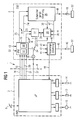
- Figure 1
- a powertrain control according to the invention;
- Figure 2
- characteristic curves of the drive train control according to FIG. 1 reflecting the time-dependent course of engine speeds and torques during a starting process;
- Figure 3
- the course of such characteristic curves in another embodiment of the drive train control according to FIG. 1, and
- Figure 4
- a fuzzy logic system of the powertrain control according to Figure 1.
Moderne Getriebesteuerungen können mit der eigenen Sensorik oder über Signale von in dem Kraftfahrzeug ohnehin vorhandenen Sensoren, die über ein CAN-Netzwerk zur Verfügung gestellt werden, eine Reihe von Informationen gewinnen oder berechnen, die einen effektiven Betrieb des Antriebsstrangs ermöglichen (siehe: Graf F, Weil G.: ,Advanced Transmission Control with Fuzzy Logic' . 3rd Int. Conference, Vehicle Comfort and Ergonomics, Bologna March 95). Diese Informationen kennzeichnen den Fahrstil des Fahrers, die Fahrbahnsteigung und/oder die Beladung des Kraftfahrzeugs. Hinzu können Informationen über einen auftretenden Radschlupf kommen. Mit der erfindungsgemäßen Antriebsstrangsteuerung erfolgt ein wesentlich umfassenderer Gebrauch dieser Informationen, um eine Anfahrkupplung und einen automatischer Anfahrvorgang angepasst an die jeweilige Fahrsituation so zu steuern, dass die Sicherheit, Komfort und Ökonomie des Kraftfahrzeugbetriebs gewährleistet ist. Modern transmission controls can use their own sensors or via signals from those already present in the motor vehicle Sensors provided over a CAN network obtain or calculate a range of information, that enable effective powertrain operation (see: Graf F, Weil G .:, Advanced Transmission Control with Fuzzy Logic '. 3rd Int. Conference, Vehicle Comfort and Ergonomics, Bologna March 95). This information characterize the driver's driving style, the road gradient and / or the loading of the motor vehicle. Add information come across an occurring wheel slip. With the Powertrain control according to the invention takes place essentially more extensive use of this information to launch a clutch and adapted an automatic starting process to control the respective driving situation so that the safety, Comfort and economy of motor vehicle operation guaranteed is.
Eine schematisch dargestellte Antriebsstrangsteuerung 1 (Figur
1) eines Kraftfahrzeugs enthält eine elektronische Motorsteuerung
(abgekürzt: EMS) 2 und eine elektronische Getriebesteuerung
(EGS) 3, die untereinander über eine Schnittstelle
4 kommunizieren, indem sie Daten über Betriebsgrößen des
Kraftfahrzeugs und Steuersignale, insbesondere in Form von
physikalischen Beschreibungsgrößen, untereinander austauschen.
Die Getriebesteuerung enthält auch eine noch zu beschreibende
Kupplungssteuerung, so dass sie der Vollständigkeit
halber als Getriebe- und Kupplungssteuerung 3 bezeichnet
werden muss. Dies wird aber im folgenden unterlassen.A schematically illustrated drive train control 1 (FIG
1) A motor vehicle contains an electronic engine control
(abbreviated: EMS) 2 and an electronic transmission control
(EGS) 3, which communicate with each other via an interface
4 communicate by providing data on the operation sizes of the
Motor vehicle and control signals, in particular in the form of
physical description sizes, exchange among themselves.
The transmission control also includes one to be described
Clutch control so that it is complete
half referred to as transmission and
Die Motorsteuerung 2 empfängt Signale von einem Fahrpedal 6
und sie weist drei Steuersignalausgaben auf: eine Signalausgabe
8 für die Drosselklappe, eine Signalausgabe 9 für die
Kraftstoffeinspritzung und eine Signalausgabe 10 zum Steuern
des Zündwinkels eines hier nicht weiter dargestellten Motors
eines Kraftfahrzeugs. Über die Signalausgabe 8 wird ein die
Drosselklappe des Kraftfahrzeugs betätigender Elektromotor 12
gesteuert. Über die Signalausgaben 9 und 10 werden Aktoren 13
beziehungsweise 14 (die zum Beispiel als piezoelektrische
oder induktive Aktoren ausgeführt sind) gesteuert, die die
einzuspritzende Kraftstoffmenge und den Zündwinkel des Motors
einstellen.The
Die Getriebesteuerung 3 enthält folgende Bestandteile: eine
Schaltsteuerung oder IPM-Steuerung 16, die ein integriertes,
d. h. gesamtheitliches Steuern des Antriebsstrangs durchführt
(IPM steht für Integrated Powertrain Management) und insbesondere
die Schaltstrategie festlegt. Sie erhält über Leitungen
18, 19 und 20 von der Motorsteuerung 2 Daten über verschiedene
Werte des Motordrehmoments (auch: Motormoments).
Über eine Leitung 21 erhält sie eine Information über das von
dem Fahrer des Kraftfahrzeugs vorgegebene Motorsollmoment
oder aber über die Stellung des Fahrpedals 6. The
Über eine Leitung 22 empfängt die IPM-Steuerung 16 die jeweilige
Abtriebsdrehzahl des Getriebes, die der Raddrehzahl und
damit - in einem vorgegebenen Verhältnis - der Geschwindigkeit
des Kraftfahrzeugs entspricht. Über eine sich verzweigende
Signalleitung 23, 24 sendet die IPM-Steuerung 16 einen
einzustellenden Zielgang oder eine Zielübersetzung an eine
Schaltübergangssteuerung 26 und an eine erste Entscheidungsschaltung
27 sowie an eine zweite Entscheidungsschaltung 28.
Diese beiden Entscheidungsschaltungen sind durch eine bidirektionale
Leitung 29 miteinander verbunden.The
Alle relevanten Informationen über die Fahrstrategie und die
jeweilige Fahrsituation gelangen über eine Leitung 25 an die
Schaltübergangssteuerung 26. Diese sendet an die zweite Entscheidungsschaltung
28 über eine Leitung 30 Steuersignale,
mit denen zum Beispiel die zeitliche Ableitung des Motordrehmoments,
d. h. die Geschwindigkeit, mit der das Motordrehmoment
verändert wird, gesteuert wird.All relevant information about the driving strategy and the
current driving situation reach the via a
Je ein Signalausgang der ersten und der zweiten Entscheidungsschaltung
27, 28 sind über Signalleitungen 32 bzw. 33
mit Anschlüssen eines Schalters 34 verbunden. Der von der
IPM-Steuerung 16 gesteuerte Schalter 34 verbindet entweder
den Ausgang der ersten Entscheidungsschaltung 27 oder den
Ausgang der zweiten Entscheidungsschaltung 28 über eine Leitung
37 mit der Motorsteuerung 2, d.h. insbesondere mit einem
Mikroprozessor 38 der Motorsteuerung, verbunden ist. Anstelle
des Schalters 34 kann auch ein Addierer 36 vorgesehen sein,
durch den die Signale auf den Leitungen 32 und 33 addiert
werden und dessen Ausgang ebenfalls über die Leitung 37 mit
der Motorsteuerung 2 verbunden ist. Über die Leitung 37
teilt die Getriebesteuerung 3 der Motorsteuerung 2 das angeforderte
Motordrehmoment mit.One signal output each from the first and the
Über eine Leitung 35 wird an die zweite Entscheidungsschaltung
28 ein Zeittakt gelegt, mit dem das Steuern der Getriebesteuerung
3 von dem Steuern der Motorsteuerung 2 getrennt
werden kann.Via a
An der Leitung 21 liegt das von dem Fahrer angeforderte Motordrehmoment
an. Dieses sogenannte Fahrerwunschmoment wird
außerhalb einer Schaltung, d. h. eines Schaltvorgangs, von
der IPM-Steuerung 16 korrigiert. Während einer Schaltung wird
es von der Schaltübergangssteuerung 26 korrigiert. Der Schalter
34 unterscheidet somit zwischen der Steuerung außerhalb
eines Schaltvorganges und der Steuerung innerhalb oder während
eines Schaltvorganges.The engine torque requested by the driver is on
Eine - vorzugsweise als Kupplungsregler ausgebildete - Kupplungssteuerung
40 empfängt von der IPM-Steuerung 16 über eine
von der Leitung 25 abzweigende Leitung 41 alle relevanten Informationen
über die Fahrstrategie und die jeweilige Fahrsituation
und über eine Leitung 42 eine Information über die
Zielposition oder das Zieldrehmoment der Kupplung, die beim
Anfahren des Kraftfahrzeugs benötigt wird. Über die Leitung
41 empfängt die Kupplungssteuerung 40 Informationen über die
jeweilige Fahrstrategie und Fahrsituation. Über die Leitung
42 empfängt sie Informationen über die Zielposition der Kupplung
und das zu übertragende Motordrehmoment, was zum Beispiel
beim Anfahren wichtig ist. Die Kupplungssteuerung 40
sendet ihrerseits über eine Leitung 43 an die IPM-Steuerung
16 und über eine Ausgangsleitung 44 an die Motorsteuerung 2
die tatsächliche Kupplungsposition oder das korrespondierende
Kupplungsdrehmoment.A clutch controller, preferably designed as a
Die Leitung 41 ist auch an die zweite Entscheidungsschaltung
28 angeschlossen, so dass an diese auch alle relevanten Informationen
über die Fahrstrategie und die jeweilige Fahrsituation
gelangen. Der Verlauf der (Signal-)Leitungen 41 und
42 ist in der Zeichnung der besseren Übersichtlichkeit wegen
nur angedeutet.
Die Kupplungssteuerung 40 ist durch einer Steuerleitung 45
mit einem Kupplungsaktuator oder Kupplungsaktor 46 verbunden,
der eine Kupplung 52 steuert. Über eine Leitung 47, die die
Schaltübergangssteuerung 26 mit der Kupplungssteuerung 40
verbindet, wird das Steuern der Kupplung mit dem Schaltvorgang
(bei einem automatisierten Handschaltgetriebe oder AMT-Getriebe)
koordiniert.The
Die Schaltübergangssteuerung 26 ist durch mehrere Steuerleitungen
48, die hier als eine Mehrfachleitung dargestellt
sind, mit elektromechanischen oder elektrohydraulischen Getriebeaktuatoren
oder Getriebeaktoren 49 verbunden, die die
Gangwechsel in einem Getriebe 53 durchführen, indem sie in
bekannter Weise Schaltgabeln des Getriebes 53 betätigen. Diese
Getriebeaktuatoren setzen dabei die Steuerbefehle in
Längs- und Drehbewegungen der Schaltgabeln um. Eine Drehbewegung
dient dem Einlegen oder Ausrücken eines Getriebegangs,
eine Längsbewegung der Gassenwahl. Einzelheiten der Gangaktuatoren
im Getriebe sind für sich bekannt (siehe zum Beispiel
R. Fischer und R. Berger (LUK), Automatisierung von
Schaltgetrieben, in dem Bericht der VDI-Tagung "Getriebe und
Fahrzeuge", 19.-20.03.1998, Seite 95 ff.).The
Die Getriebesteuerung 3 ist mit einer Erkennungsschaltung 50
versehen, die dazu dient, die jeweiligen Fahrsituationen des
Kraftfahrzeuges zu erkennen, wie da sind: Anfahren, Rangieren,
beschleunigte, gleichmäßige oder verzögerte Fahrt, Bergauf-
oder Bergabfahrt, Kurvenfahrt, Fahrt innerörtlich, auf
Landstraßen oder Schnellstraßen, Fahrt bei winterlichen Straßenzuständen
usw. Die Erkennungsschaltung 50 ist im vorliegenden
Ausführungsbeispiel als Fuzzylogikrechner oder -regler
ausgebildet und Bestandteil der IPM-Steuerung 16. Sie wertet
Sensorsignale aus, die in der Getriebesteuerung 3 ohnehin
vorliegen und von dieser ausgewertet werden, wie es in dem
eingangs zitierten Beitrag von F. Graf und H. Weil und in der
genannten EP 0 576 703 A1 erläutert wird. The
Die Getriebesteuerung 3 ist auch mit einem Kennfeldspeicher
51 versehen, der Kennlinien enthält, die dazu dienen, den Antriebsstrang
- und insbesondere die Kupplung 52 - beim Anfahren
des Kraftfahrzeugs angepasst an die jeweilige Umgebungs-
und Anfahrsituationen zu steuern. Der Kennfeldspeicher 51 ist
im vorliegenden Ausführungsbeispiel Bestandteil der IPM-Steuerung
16. Die IPM-Steuerung 16 ist zentraler und wichtigster
Teil der Steuerung des Antriebsstrangs, sie koordiniert
die Funktion seiner sämtlichen Einzelbestandteile. Sie wird
deshalb auch als Meta-Controller bezeichnet. Die IPM-Steuerung
16 ist hier zwar als in der Getriebesteuerung 3
enthalten dargestellt, dies ist aber nicht notwendig. Sie
kann auch anderswo, zum Beispiel in der Motorsteuerung 2 untergebracht
sein.The
Entscheidend für eine individuelle Optimierung der Antriebsstrangsteuerung
1 nach den in der jeweiligen Situation maßgeblichen
Kriterien ist eine sichere Erkennung der aktuellen
Fahrsituation oder Fahrmanöver. Durch die Fahrsituationserkennung
innerhalb der adaptiven Schaltstrategie, die von der
IPM-Steuerung 16 realisiert wird, ist es möglich, Fahrleistungsanforderugen
nicht nur in ihrer Intensität, sondern
auch in ihrem dynamischen Anspruch zu klassifizieren. Insbesondere
erkennt sie Anfahrsituationen und deren Varianten,
wie Rangieren, Anfahren am Berg, Stop-and-go-Fahrt usw.Crucial for an individual optimization of the
Im Rahmen von Programmen, wie sie von dem Fuzzylogikrechner
oder -regler aus der EP 0 576 703 A1 verarbeitet werden, arbeitet
die Erkennungsschaltung 50 Fuzzylogikprogramme wie
folgt ab:
Das Fuzzylogikprogramm für die Erkennungschaltung 50, die
auch als Unterprogramm innerhalb der IPM-Steuerung ausgebildet
sein kann, lautet wie folgt:
Eine besonders vorteilhafte Nutzung von fahrstrategie- und
fahrsituationsrelevanten Informationen ist die davon abhängige
Gestaltung des Anfahrvorganges. Ist das Kraftfahrzeug mit
einem üblichen Kupplungssteuerungssystem versehen, so wird
beim Anfahren ein vorgegebener Verlauf der Motordrehzahl oder
aber die Differenzdrehzahl, d. h. der Schlupf, reproduziert
(Figur 2). Es sei darauf hingewiesen, daß zwar im folgenden
Text die Rede von einer Trockenkupplung ist, die Erläuterungen
aber auch genauso für eine naßlaufende, hydraulisch betätigte
Kupplung gelten.In the context of programs such as those processed by the fuzzy logic computer or controller from EP 0 576 703 A1, the
The fuzzy logic program for the
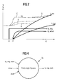
A particularly advantageous use of information relevant to driving strategy and driving situation is the design of the starting process that is dependent on it. If the motor vehicle is provided with a conventional clutch control system, a predetermined course of the engine speed or else the differential speed, ie the slip, is reproduced when starting off (FIG. 2). It should be noted that although the following text speaks of a dry clutch, the explanations also apply to a wet-running, hydraulically operated clutch.
In Figur 2 ist der zeitliche Verlauf folgender Größen beim Anfahren eines Kraftfahrzeugs dargestellt: die Motordrehzahl ne, die Getriebeeingangsdrehzahl n,ein und die Getriebeausgangsdrehzahl n,aus. Gibt der Fahrer eines stehenden Kraftfahrzeugs zu einem Zeitpunkt t0 Gas, so wird bei noch geöffneter Kupplung die Motordrehzahl erhöht, bis zu einem Zeitpunkt tl die Kupplung eingerückt wird. Anschließend beginnt das Fahrzeug - bedingt durch die Übertragung des Motordrehmoments über den Antriebsstrang - zu beschleunigen. Die Drehzahl ne zu dem Zeitpunkt tl hat maßgeblichen Einfluß auf die Fahrbarkeit des Kraftfahrzeugs, da die eingestellte Motordrehzahl mit einem zugehörigen Motordrehmoment gekoppelt ist. Dies beeinflusst die Dosierung der Motordrehzahl zum Beispiel beim Rangieren, bei Beschleunigungen und bei der Bergauffahrt. Außerdem beeinflusst es den Kraftstoffverbrauch. Unangepaßte Motordrehzahlen können auch zu einem Abwürgen des Motors führen.In Figure 2, the course of the following variables over time Starting a motor vehicle shown: the engine speed ne, the transmission input speed n, on and the transmission output speed n, off. Gives the driver of a stationary motor vehicle at a point in time t0 gas, the gas is still open Clutch increases the engine speed up to a point in time tl the clutch is engaged. Then starts the vehicle - due to the transmission of the engine torque via the drive train - to accelerate. The speed ne at the time tl has a significant influence on the Drivability of the motor vehicle because of the set engine speed coupled with an associated engine torque is. This affects the metering of the engine speed Example when maneuvering, accelerating and when Uphill. It also affects fuel consumption. Improper engine speeds can also stall of the engine.
Dargestellt sind weiterhin das von dem Fahrer mit dem Fahrpedal
angeforderte oder bewirkte Motor(dreh)moment tq,eng und
das Rad(dreh)moment tq,wheel. Bei herkömmlichen Antriebsstrangsteuerungen
ist das Raddrehmoment eine sich aus dem Motordrehmoment
und der Getriebeübersetzung ergebende Größe,
sie wird dort nicht als Führungsgröße für die Regelung des
Antriebsstrangs verwendet. Auch benutzen herkömmliche Antriebsstrangsteuerungen
nur eine Kennlinie für den Anfahrvorgang.
Die vorliegende Antriebsstrangsteuerung 1 hingegen verwendet
für unterschiedliche Anfahrsituationen jeweils an diese
angepasste Kennlinien.The driver with the accelerator pedal is also shown
Requested or effected motor (torque) tq, narrow and
the wheel (turning) moment tq, wheel. With conventional powertrain controls
the wheel torque is a result of the engine torque
and the size resulting from the gear ratio,
it is not used as a reference variable for the regulation of the
Powertrain used. Also use conventional powertrain controls
only one characteristic curve for the starting process.
The present
Eine gestrichelte Linie A (Figur 2) gibt den für das Rangieren typischen Verlauf der Motordrehzahl ne wieder, eine Linie B deren Verlauf für einen komfortablen, drehzahlreduzierten und wirkungsgradoptimalen Anfahrvorgang und eine Linie C den Verlauf von ne für einen sogenannten ,Racing Start' (sogenannter Kavaliersstart) oder für ein Anfahren am Berg.A dashed line A (Figure 2) indicates that for maneuvering typical course of the engine speed ne again, a line B their course for a comfortable, reduced speed and efficiency-optimized starting process and a line C den Course of ne for a so-called 'racing start' (so-called Cavalier start) or for a start on the mountain.
Die hier erstmals angewandte Anpassung der Motordrehzahl an die jeweils vorliegende Anfahrsituation berücksichtigt die Wechselwirkung zwischen der von der Kupplungssteuerung eingestellten Motordrehzahl und der Charakteristik des jeweiligen Motors. Ein höheres oder gar das maximale Motordrehmoment werden erst bei Drehzahlen über 3000 U/min. erreicht (dies gilt insbesondere für Benzinmotoren).The adaptation of the engine speed used here for the first time the present starting situation takes into account the Interaction between the one set by the clutch control Engine speed and the characteristics of each Motors. A higher or even the maximum engine torque are only at speeds above 3000 rpm. reached (this applies in particular to petrol engines).
Die Berücksichtigung der Motorcharakteristik ermöglicht es,
sofort die bestmögliche Beschleunigung zu realisieren. Das
bedeutet, daß der Antriebsstrang abhängig von den Umwelt- und
Fahrbedingungen gesteuert wird. Wenn zum Beispiel ein Fahrer
bei im Economy-Fahrprogramm befindlicher Getriebesteuerung
sein Kraftfahrzeug plötzlich stark beschleunigt, erhöht die
Antriebsstrangsteuerung 1 zuerst die Motordrehzahl und rückt
danach die Kupplung 52 ein. Dies bewirkt eine schnellere Beschleunigung
als das übliche Hochfahren des Motordrehmoments
bei geschlossener Kupplung.Taking into account the engine characteristics enables
to immediately realize the best possible acceleration. The
means that the powertrain is dependent on the environmental and
Driving conditions is controlled. If for example a driver
with transmission control in the economy drive program
his motor vehicle suddenly accelerates sharply, which increases
Das Regeln oder Steuern der Motordrehzahl durch die Kupplungssteuerung
40 beeinflusst also mittelbar (indirekt) das
Motordrehmoment. Dazu werden die notwendigen Informationen
über die Fahrsituationserkennung von der Erkennungsschaltung
50 über die Leitungen 25, 41 an die lokale Kupplungssteuerung
40 übermittelt. Diese setzt dann die Informationen durch Auswahl
einer der Anfahrsituation entsprechenden Kennlinie - die
weiter hinten noch erläutert werden - in einen wirksamen
Steuerungsvorgang um. Spezielle Kennlinien können auch für
den Winterbetrieb oder den Betrieb bei bereits thermisch
stark beanspruchter Kupplung vorgesehen sein.The regulation or control of the engine speed by the
Der sogenannte Meta-Controller 16 kann gemäß den Fahrervorgaben
die Kupplungssteuerung 40 parametrieren. Er verfügt über
Kennlinien für die Motordrehzahl in Form einer Funktion ne =
f(tq,eng,nom; t), wobei tq,eng,nom das angeforderte Motordrehmoment
und t die Zeit ist.The so-called
Dabei kann der Fahrer über das Fahrpedal 6 je nach der vorhandenen Motorsteuerung eine Drosselklappenstellung oder ein Soll-Motordrehmoment tq,eng,nom anfordern. Es sei im vorliegenden Beispiel vorausgesetzt, daß das Motordrehmoment trotz konstanter Fahrpedalstellung mit der Motordrehzahl variiert, so wie es zum Beispiel dem Verhalten eines Motors mit mechanischer Motorlaststeuerung entspricht.The driver can use the accelerator pedal 6 depending on the existing one Engine control a throttle position or a Request target engine torque tq, eng, nom. It is in the present Example provided that the engine torque varies with engine speed despite constant accelerator pedal position, such as the behavior of an engine, for example corresponds to mechanical engine load control.
Eine noch vorteilhaftere Anpassung der Antriebsstrangsteuerung
1 an unterschiedliche Fahrstile und Anfahrbedingungen
wird mit dem nachfolgenden Ausführungsbeispiel erreicht. Bei
diesem wird das Motormoment und damit auch das Radmoment
nicht nur indirekt durch an die Kupplungsteuerung angepaßte
und durch die Schaltstrategie bestimmte Motordrehzahlverläufe
beeinflußt, sondern es wird zusätzlich das Motormoment gesteuert,
um einen Soll-Radmomentverlauf zu erreichen, der aus
der Fahrpedalstellung berechnet wird.An even more advantageous adaptation of the
Es wird also vorausgesetzt, daß das Fahrpedal grundsätzlich ein Soll-Radmoment vorgibt. Dieses wird zum Beispiel unter Verwendung von Fahrsituationsinformationen ermittelt, so wie es in der Anmeldung DE 196 48 055 A1 beschrieben ist. Die Steuerungstrategie folgt grundsätzlich dieser Art von (Primär-) Fahrpedalinterpretation.It is therefore assumed that the accelerator pedal is fundamentally specifies a target wheel torque. This is for example under Use of driving situation information determined, such as it is described in the application DE 196 48 055 A1. The Control strategy basically follows this type of (primary) Accelerator pedal interpretation.
Das so ermittelte Soll-Radmoment wird aufgelöst in Sollvorgaben
für das Motordrehmoment und die Kupplungsstrategie einerseits
und für die Motor-Solldrehzahl andererseits. Damit ergibt
sich direkt ein eingeprägtes Führen des Motors, das dynamisch
optimiert wird. Eine Beeinflussung des Radmoments indirekt
durch die Drehzahlführung und damit durch das Motordrehmoment
entfällt bei diesem Ausführungsbeispiel, der
Antriebstrang folgt strikt der Vorgabe des Fahrers, und dies
erleichtert die Fahrbarkeit des Kraftfahrzeugs. Es gilt der
folgende Zusammenhang:
Darin sind:
- tq,eng,nom
- das Soll-Motormoment
- I
- die Übersetzung des eingelegten Anfahrganges
- nom
- ein Sollwert
- tq, narrow, nom
- the target engine torque
- I.
- the translation of the selected starting gear
- nom
- a setpoint
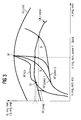
Es gibt unterschiedliche Möglichkeiten, das geforderte das Soll-Motormoment tq,eng,nom in Abhängigkeit von ne zu realisieren. Dies wird nun anhand von Figur 3 erläutert.There are different options, the required To achieve target engine torque tq, narrow, nom as a function of ne. This will now be explained with reference to FIG. 3.
Da eine Trocken- und auch eine Naßkupplung (in Lamellenbauweise) im Gegensatz zu einem Drehmomentwandler kein Drehmoment verstärken können, leitet sich bei ihnen das Soll-Motordrehmoment direkt aus dem Soll-Radmoment ab, wie aus Gleichung (I) ersichtlich ist. Soll das angeforderte Radmoment beim Anfahren möglichst effizient genutzt werden, muss eine verbrauchsoptimierte Kennlinie A in dem Kennfeld nach Figur 3 überstrichen werden. Diese Kennlinie wird zusammen mit dem Motor-Verbrauchskennfeld erstellt und sie dient dazu, bei einer bestimmten Rad- oder Motormomentanforderung den verbrauchsminimalen Motordrehzahlwert zu ermitteln, d. h. die Motordrehzahl, die den geringsten Kraftstoffverbrauch ergibt. Damit lassen sich die Führungsgrößen tq,eng,nom und tq,clutch für die Motor- und die Kupplungsteuerung bilden. Vernachlässigt werden dabei dynamische Drehmomentanteile, die zum Beispiel erforderlich sind, um die Motordrehzahl auf einen bestimmten Wert einzustellen. Since a dry and also a wet clutch (in multi-plate design) unlike a torque converter, no torque can increase the target engine torque directly from the target wheel torque, as from Equation (I) can be seen. Should the requested wheel torque must be used as efficiently as possible when starting off a consumption-optimized characteristic curve A in the map Figure 3 are painted over. This characteristic curve is put together created with the engine consumption map and it serves to for a specific wheel or engine torque request determine the minimum engine speed value, d. H. the Engine speed that gives the lowest fuel consumption. This enables the reference variables tq, eng, nom and tq, clutch form for the engine and clutch control. Neglected are dynamic torque components, for example are required to set the engine speed to a specific Value.
Das Soll-Motordrehmoment wird durch die Drehzahlregelung in
der Kupplungsteuerung 40 eingestellt. Die Zieldrehzahl für
diese Drehzahlregelung wird auch anhand der Kennlinie AP,eco
gewonnen. Die aus dem Diagramm von Figur 3 abgeleitete Soll-Motordrehzahl
n,eng,nom entspricht der Anfahrdrehzahl zum
Zeitpunkt t1 (Figur 2), bei der die Kupplung zu schließen beginnt
(sogenannter Berührpunkt). Im weiteren Verlauf bis zum
vollständigen Schließen der Kupplung zum Zeitpunkt t2 kann
die Motordrehzahl gemäß Figur 2 nachgeführt werden, falls
die Lastanforderung sich ändert (Kurve D).The target engine torque is set by the speed control in the
Bei besonders einfachen Antriebsstrangsteuerungen, die über keine Drehzahlregelung verfügen, können in einem Kennlinienspeicher - statt der Solldrehzahlverläufe als Funktion der Soll-Drehmomente - Kupplungspositions-Kennlinien abgelegt sein. Überlagert wird ihnen eine Zeitfunktion, um den Kupplungsschlupf abzubauen.In the case of particularly simple drive train controls which are operated via have no speed control, can be stored in a characteristic curve - Instead of the target speed curves as a function of Target torques - clutch position characteristic curves stored his. A time function is superimposed on the clutch slip dismantle.
Die beschriebene Steuerung des Antriebsstrangs anhand der
AP,eco-Kennlinie von Figur 3 ergibt einen sehr geringen
Kraftstoffverbrauch bei Startvorgängen. Eine wirksame Schonung
der Kupplung ergibt sich aus geringen Differenzdrehzahlen.
Mit der Kennlinie AP,eco lassen sich alle vom Fahrer
benötigten Drehmomente (und zwar bis zum absoluten Drehmomentmaximum
M) mit - von der vorgegebenen Betriebsstrategie
abhängenden - unterschiedlichen Drehzahlen bereitstellen. Bei
einer Mehranforderung von Drehmoment in einem großen Schritt,
wie sie dem Übergang von einem Punkt x1(n,eng,nom,eco) zu
einem Punkt M(n,eng,nom,power1) in dem Kennfeld von Figur 3
entspricht, wird ausgekuppelt, um den Motor mit Drehmoment
zum Hochdrehen zu versorgen. Dies gibt folgende Gleichung
wieder.
Darin sind:
- J
- das Trägheitsmoment des Motors
- delta_ne,eng,nom
- der Drehzahlsprung des Motors
- delta_t
- die erforderliche Zeit
- J
- the moment of inertia of the motor
- delta_ne, narrow, nom
- the speed jump of the engine
- delta_t
- the time required
Dieser Vorgang reduziert allerdings die Fahrleistung. Besser
ist es deshalb, bei durch die IPM-Steuerung 16 vorausschauend
erkannter (zum Beispiel aus der Fahrweise) Absicht des Fahrers
zu beschleunigen oder auch bei einem hohem Fahrwiderstand
ein höheres Motordrehzahlniveau einzustellen, wie das
der Kennlinie AP,power1 entspricht Damit wird ein zügiges,
gleichförmiges Anfahren und Beschleunigen des Fahrzeugs erreicht.
Bei Fahrzeugen mit sehr sportlichen Charakter kann
auch die Kennlinie AP,power2 verwendet werden (für einen
sogenannten Racing-Start), oder auch bei einer fahrleistungsorientierten
Situation (zum Beispiel beim Überholen). Dies
kann auch manuell ausgelöst werden, und zwar auch bei anderen
Betriebsmoden, wenn über die automatische Betriebspunkterzeugung
hinaus auch ein Eingriff des Fahrers möglich ist (entsprechende
Taster sind häufig im Kraftfahrzeug für eine
Schaltprogrammauswahl vorhanden).However, this process reduces driving performance. Better
it is, therefore, foresighted by the
Die leistungsorientierten Kennlinien stellen auch eine gute Möglichkeit dar, um Fahrspaß oder Fahrbarkeit zu vermitteln, zum Beispiel bei einem Racing-Start bzw. bei einem Anfahren am Berg. Allerdings ist dabei die Kupplung einer hohen Wärmebelastung ausgesetzt, da sie eine hohe Differenzdrehzahl aufnehmen muß. AP,power2 ist die Kennlinie maximalen Drehmoments, DK=konst ist die Linie konstanter Drosselklappenstellung und VL ist die Volllastkennlinie des Motors.The performance-oriented characteristics also represent a good one Possibility to convey driving pleasure or driveability for example at a racing start or when starting off on the mountain. However, the coupling is a high heat load exposed because they absorb a high differential speed got to. AP, power2 is the characteristic curve of maximum torque, DK = const is the line of constant throttle valve position and VL is the full load characteristic of the engine.
Die verbrauchsoptimierte Kennlinie AP,eco, die die - in der Zeichnung nicht dargestellten - Linien konstanten spezifischen Verbrauchs senkrecht schneidet, stellt bei unterschiedlich angeforderten Motordrehmomenten dagegen den geringsten Verbrauch sicher. Dies ist entscheidend bei einem Betrieb im Stadtverkehr, um minimale Verbräuche zu realisieren. Darüber hinaus können je nach Betriebsart des Motors (wie etwa bei GDI: Schichtladungs-/ homogener Betrieb) dem Motorbetrieb unterschiedliche Verläufe eingeprägt werden, um bezüglich der Verbrennungsstabilität, günstige Arbeitsbereiche des Motors zu erhalten.The consumption-optimized characteristic curve AP, eco, which - in the Drawing not shown - constant specific lines Consumption cuts vertically, sets at different requested engine torque, however, the lowest Consumption safe. This is crucial when operating in City traffic to achieve minimal consumption. About that Depending on the operating mode of the engine (such as at GDI: stratified charge / homogeneous operation) different from engine operation Gradients can be imprinted in order to Combustion stability, favorable working areas of the engine to obtain.
Übermäßige Hitzeentwicklung in der Kupplung, die zum Beispiel
durch eine thermische Modellrechnung in der IPM-Steuerung 16
erkannt wird, kann bei anhaltenden Startvorgängen (etwa ein
permanentes Anfahren am Berg) zu einer Reduktion der Motor-Solldrehzahl
ne,nom führen. Es ist wichtig, diese Änderung im
Systemverhalten dem Fahrer mitzuteilen (durch ein akustisches
oder optisches Warnsignal). Generell sichert die Antriebsstrangsteuerung
1 die für den jeweiligen Startvorgang beste
Lösung, ohne daß der Fahrer dies (zum Beispiel über Taster)
vorgeben muß .Excessive heat in the clutch, for example
by means of a thermal model calculation in the
Ein weiteres nützliches Merkmal der Antriebsstrangsteuerung 1
ist der Kriechmodus (creep-mode) des Kraftfahrzeugs. Er betrifft
den Betriebsfall des Rangierens und er wird mit der
Kennlinie AP,creep (Figur 3) gesteuert. Bei dem Ausführungsbeispiel
gemäß Figur 2 wird das Fahrpedal auch skaliert,
und zwar durch die IPM-Steuerung 16, die diesen Betriebsfall
auch erkennt. Dabei wird die Empfindlichkeit für kleine Fahrpedalwerte
reduziert. Darüber hinaus ist ein frühes Einkuppeln
sinnvoll, um die Schleifzeit der Kupplung 52 zu begrenzen.
In dem Betriebsfall ,erhöhte Last' muss andererseits die
Soll-Motordrehzahl erhöht werden.Another useful feature of
Die Sollradmoment-Vorgabe in der Antriebsstrangsteuerung 1
ergibt einen weiteren Freiheitsgrad beim Steuern, der dazu
benutzt wird, eine fahrsituationsspezifische Zuordnung der
Fahrpedalstellung zu dem Soll-Radmoment vorzunehmen. Damit
lässt sich im Rangierbetrieb oder im Rückwärtsgang ein geringeres
Radmoment bei gleicher Fahrpedalstellung erreichen, womit
das Fahrzeug feinfühliger bewegt werden kann. Dies ergibt
erhebliche Verbesserungen gegenüber einer ausschließlichen
Behandlung dieses Modus durch Steuern der Soll-Motordrehzahl.
Diese Möglichkeit kann soweit ausgebaut werden, daß ein Verhalten
ähnlich einem Drehmomentwandler erzeugt wird. Ein Beispiel
dafür ist, daß ein großer Anfahrwiderstand ein größeres
Radmoment benötigt. In diesem Fall wird ein größeres Soll-Radmoment,
mit einem daraus sich ergebenden höheren Motordrehmoment
vorgegeben. Durch diese Anhebung des Motordrehmoments
erübrigt sich eine größere Anhebung der Motordrehzahl,
womit der Kupplungsverschleiß reduziert wird.
Durch Festlegen der Arbeitspunkte der Antriebsstrangsteuerung
1 mit den Kennlinien AP,power1 und AP,power2 wird das jeweils
günstigste Motordrehzahlniveau mit einer ausreichender
Motormomentenreserve zur Verfügung gestellt.The target wheel torque specification in the
Falls es die jeweils gegebenen Anfahrbedingungen erfordern, können in einfacher Weise auch Zwischenwerte zwischen den Kennlinien der Figur 3 generiert werden, zum Beispiel durch eine Interpolation zwischen den Kennlinien AP,eco und AP,power1 oder AP,power2.If the given starting conditions require it, can also easily intermediate values between the Characteristic curves of Figure 3 are generated, for example by an interpolation between the characteristic curves AP, eco and AP, power1 or AP, power2.
Neben der beschrieben Generierung von Solldrehzahlen anhand
von Kennlinien können sie auch mit einem ein Fuzzy-Logik-System
55 erzeugt werden (Figur 4). Dieses System empfängt
als Eingangssignale die Größen tq,eng,nom, Fahrerwert
und/oder Lastwert und berechnet daraus eine Soll-Motordrehzahl
n,eng,nom. Ein solches Fuzzy-Logik-System ist
in dem genannten Aufsatz von F. Graf und H. Weil beschrieben.
Es arbeitet hier einen aus folgenden Regeln (rules) bestehenden
Fuzzylogik-Regelsatz ab:
Grundsätzlich lassen sich alle diese in Kennfeldern abgelegte
Kennlinien und die gleichwertigen Fuzzy-Systemausgangsgrößen
auch auf ein Kupplungssteuerungssystem 16, 40 übertragen, das
als Regelgröße die Differenzdrehzahl zwischen der Motor- und
der Getriebeeingangsdrehzahl besitzt. Dabei muß aber die
Sollwertvorgabe bis zu dem Zeitpunkt t2 auf null absinken.Basically, all of these can be stored in maps
Characteristic curves and the equivalent fuzzy system output variables
also transferred to a
Das Raddrehmoment wird in der IPM-Steuerung 16 erfasst. Diese
kann - zusätzlich zu einer Vorgabe des Motordrehmoments durch
den Fahrer über das Fahrpedal 6 an die Motorsteuerung 2 - eine
Korrektur des Raddrehmoments bewirken. Dies geschieht über
die Schaltungsbestandteile 27, 28 und die Leitungen 18-21 und
37 der Antriebsstrangsteuerung 1. Durch die Entscheidungsschaltung
27 wird das Soll-Radmoment in ein (korrigiertes)
Soll-Motormoment transformiert.The wheel torque is recorded in the
Über die Leitung 42 ermittelt die Kupplungsteuerung 40 das
angeforderte Soll-Radmoment und damit das Soll-Kupplungsdrehmoment
(der einlegte Gang ist der Kupplungssteuerung
bekannt). Damit läßt sich die Lage der Kupplung
vorsteuern und somit eine bessere Regelgüte erreichen. Über
die Leitung 43 wird es der IPM-Steuerung 16 mitgeteilt, wenn
Einschränkungen in der Kupplungsfunktion vorliegen, zum Beispiel
bei Überhitzung. Dann kann ein daraus resultierender
Ausfall von fahrleistungsorientierten Manövern oder von
Kriechbetrieb, d. h. ein Wegfall von in der Kupplung eine
Verlustleistung bewirkenden Betriebsarten, erforderlichenfalls
durch eine Anhebung des Radmoments und damit des Motormoments
(erst bei geschlossener Kupplung) ausgeglichen werden.
Dies schont den Kupplungsbelag. The
Hier wird ein weiterer Vorteil der Antriebsstrangsteuerung 1
deutlich: Das Motordrehmoment kann auch abhängig vom Kupplungszustand
gesteuert werden, und zwar wenn nötig unter
Nichtbeachtung des vorgegebenen Raddrehmoments, das erst bei
vollständig geschlossener Kupplung vorliegt.Here is another advantage of
Werden die Schaltungsbestandteile 10, 16 26-28, 40 und die
zugehörigen Signalleitungen zusammengefaßt, so bilden sie ein
integriertes Kupplungs- und Motormanagement. Die aus der Figur
3 ersichtlichen Kennlinien sind wie erwähnt in dem Kennfeldspeicher
51 der IPM-Steuerung 16 abgelegt, die eine ganzheitliche
Realisierung der Steuerung eines Antriebsstrangs
darstellt und deshalb auch als sogenannter Meta-Controller
bezeichnet wird.Are the
Ein weiterer Vorteil einer derartigen Antriebsstrangsteuerung
1 mit integrierter Motorbeeinflussung ist, daß durch die
Kupplungssteuerung verursachte Drehzahländerungen keine Veränderung,
zum Beispiel Reduktion, des Motordrehmoments nach
sich ziehen. Dies kann bei Systemen vorkommen, die das Fahrpedal
quasi aufspannen zwischen dem minimalen und dem maximalen
Drehmoment bei Vollast, da diese Extrema drehzahlabhängig
sind. Dies kann zu dem Effekt führen, daß dadurch das Radmoment
sinkt - und durch den Fahrer ausgeglichen werden muß.
Die IPM-Steuerung als Meta-Controller entkoppelt die Betriebsgrößen,
so dass über die (Schnittstellen-)Leitung 37 das
von dem Fahrer angeforderte (= requested) Motordrehmoment
tq,eng,req korrigiert werden kann, und zwar durch Übermitteln
eines Differenzdrehmoments delta_tq,eng,req über die
Leitung 37.Another advantage of such a
Von der Getriebesteuerung 3 wir über die Leitung 37 nicht nur
ein statischer Korrekturwert an die Motorsteuerung 2 übertragen,
es kann erforderlichenfalls über einen separaten Übertragungskanal
auch die Drehmomentdynamik des Motors beeinflusst
werden. Dies ist dann von Vorteil, wenn die Dynamik
der Kupplungsregelung im Hinblick auf das Drehmoment geringer
ist als die des Motors. Außerdem ist von Vorteil, daß die Motorsteuerung
2 für verschiedene Motortypen bis auf die notwendigen
Schnittstellen unverändert bleiben kann, insbesondere
was die Interpretation der Fahrpedalstellung anbelangt.From the
Der Kennlinienspeicher oder das Fuzzy-Logik-System können bei
einem anderen Ausführungsbeispiel auch in der Kupplungssteuerung
40 lokalisiert sein. In diesem Fall wird der Antriebsstrang
über das angeforderte Motordrehmoment tq,eng,req (das
in der Motorsteuerung 2 berechnet wird) geführt. Die erforderliche
Information gelangt über die Schnittstellenleitungen
18-21 zu der Getriebe- und Kupplungssteuerung 3.The characteristic curve memory or the fuzzy logic system can be used for
another embodiment also in the
Eine weitere Variante der Antriebsstrangsteuerung besteht
darin, der Motorsteuerung 3 über die Leitung 44 direkt eine
Soll-Motordrehzahl vorzugeben. Diese wird dann durch einen
Drehzahlregler der Motorsteuerung 3 geregelt. Diese Variante
hat den Vorteil, daß die Kupplungssteuerung 40 keinen motorspezifischen
Regler und Reglerparameter enthalten muss. Außerdem
entfällt die Möglichkeit einer Kollision zwischen in
der Kupplungssteuerung 40 und in der Motorsteuerung 3 enthaltenen
Reglern. Die Motorsteuerung enthält statt dessen eine
Entscheidungslogik, mit der die Drehzahlführung eindeutig
festgelegt wird.Another variant of the drive train control exists
therein, the
Claims (10)
Priority Applications (7)
| Application Number | Priority Date | Filing Date | Title |
|---|---|---|---|
| DE59906521T DE59906521D1 (en) | 1999-08-24 | 1999-08-24 | Control for the drive train when starting a motor vehicle |
| EP99116567A EP1078805B1 (en) | 1999-08-24 | 1999-08-24 | Control of vehicle driveline during vehicle start and drive-off |
| KR1020027002377A KR100660244B1 (en) | 1999-08-24 | 2000-08-22 | Control system for the drive train of a motor vehicle |
| JP2001518278A JP3987722B2 (en) | 1999-08-24 | 2000-08-22 | Control device for automobile drive train |
| PCT/EP2000/008196 WO2001014163A1 (en) | 1999-08-24 | 2000-08-22 | Control system for the drive train of a motor vehicle |
| ARP000104382A AR025370A1 (en) | 1999-08-24 | 2000-08-24 | COMMAND FOR THE MOTOR GROUP OF AN AUTOMOTIVE VEHICLE. |
| US10/082,332 US6507780B2 (en) | 1999-08-24 | 2002-02-25 | Controller for the drive train of a motor vehicle |
Applications Claiming Priority (1)
| Application Number | Priority Date | Filing Date | Title |
|---|---|---|---|
| EP99116567A EP1078805B1 (en) | 1999-08-24 | 1999-08-24 | Control of vehicle driveline during vehicle start and drive-off |
Publications (2)
| Publication Number | Publication Date |
|---|---|
| EP1078805A1 true EP1078805A1 (en) | 2001-02-28 |
| EP1078805B1 EP1078805B1 (en) | 2003-08-06 |
Family
ID=8238842
Family Applications (1)
| Application Number | Title | Priority Date | Filing Date |
|---|---|---|---|
| EP99116567A Expired - Lifetime EP1078805B1 (en) | 1999-08-24 | 1999-08-24 | Control of vehicle driveline during vehicle start and drive-off |
Country Status (7)
| Country | Link |
|---|---|
| US (1) | US6507780B2 (en) |
| EP (1) | EP1078805B1 (en) |
| JP (1) | JP3987722B2 (en) |
| KR (1) | KR100660244B1 (en) |
| AR (1) | AR025370A1 (en) |
| DE (1) | DE59906521D1 (en) |
| WO (1) | WO2001014163A1 (en) |
Cited By (8)
| Publication number | Priority date | Publication date | Assignee | Title |
|---|---|---|---|---|
| FR2823822A1 (en) * | 2001-04-20 | 2002-10-25 | Luk Lamellen & Kupplungsbau | Controlling/regulating automated vehicle gearbox, involves taking into account pedal value and/or driver's desired torque as input parameter for evaluating shift characteristic for shift strategy |
| WO2003002368A1 (en) | 2001-06-28 | 2003-01-09 | Siemens Aktiengesellschaft | Method for controlling a drivetrain on a motor vehicle |
| FR2834940A1 (en) * | 2002-01-22 | 2003-07-25 | Renault | METHOD AND CONTROL DEVICE FOR A MOTORPROPELLER UNIT FOR VEHICLE |
| DE10202520A1 (en) * | 2002-01-24 | 2003-08-14 | Bayerische Motoren Werke Ag | Drive train control for motor vehicle modifies starting acceleration characteristics according to the particular need |
| WO2003106211A1 (en) * | 2002-06-17 | 2003-12-24 | Siemens Aktiengesellschaft | Method for controlling a torque |
| DE10260838A1 (en) * | 2002-12-23 | 2004-07-15 | Volkswagen Ag | Method and device for controlling a clutch within a motor vehicle drive train |
| FR2866682A1 (en) * | 2004-02-25 | 2005-08-26 | Renault Sas | Torque controlling method for vehicle, involves correcting torque set point transmitted by clutch when specific conditions are satisfied, and by applying correction factor associated with ratio of degradation between torques, to point |
| DE10315537B4 (en) * | 2002-04-08 | 2017-04-20 | General Motors Corp. (N.D.Ges.D. Staates Delaware) | A method of maintaining a constant engine idle speed of a vehicle equipped with an automatic transmission |
Families Citing this family (20)
| Publication number | Priority date | Publication date | Assignee | Title |
|---|---|---|---|---|
| DE10221263B4 (en) * | 2001-05-17 | 2016-11-17 | Schaeffler Technologies AG & Co. KG | Method for controlling and / or regulating a torque transmission system in a drive train of a vehicle |
| JP4383072B2 (en) * | 2002-03-26 | 2009-12-16 | ロベルト・ボッシュ・ゲゼルシャフト・ミト・ベシュレンクテル・ハフツング | Method for determining clutch state of vehicle and apparatus for implementing the same |
| KR100448381B1 (en) * | 2002-06-28 | 2004-09-10 | 현대자동차주식회사 | Shift control method and apparatus of an automatic transmission |
| DE10243495A1 (en) * | 2002-09-19 | 2004-03-25 | Daimlerchrysler Ag | Vehicle automatic transmission operation, determines corrected running parameters as function of initial- and final engine speeds |
| DE102004006880B4 (en) * | 2004-02-12 | 2008-05-08 | Robert Bosch Gmbh | Method for controlling the engine of a motor vehicle with manual transmission |
| US7222012B2 (en) * | 2004-06-15 | 2007-05-22 | Gm Global Technology Operations, Inc. | Axle torque based powertrain braking with range selection for coordinated torque control (CTC) |
| FR2875204B1 (en) * | 2004-09-10 | 2006-12-01 | Renault Sas | METHOD FOR PRODUCING A CONTROL SET FOR A BRAKING SITUATION FOR A DEVICE FOR TRANSMITTING A VEHICLE MOTOR POWERTRAIN AND CORRESPONDING DEVICE |
| FR2875202B1 (en) * | 2004-09-10 | 2008-02-01 | Renault Sas | METHOD FOR CONTROLLING MULTIPLE OPERATING MODES OF AN AUTOMATED TRANSMISSION FOR A MOTOR VEHICLE, IN PARTICULAR FOR AN IDLE-END ADVANCEMENT OF THE MOTOR VEHICLE WITHOUT BRAKE ACTIVATION OF THE MOTOR VEHICLE |
| FR2875201B1 (en) * | 2004-09-10 | 2006-12-01 | Renault Sas | METHOD FOR CONTROLLING MULTIPLE OPERATING MODES OF AN AUTOMATED TRANSMISSION FOR A MOTOR VEHICLE, IN PARTICULAR FOR AN IDLE-END ADVANCEMENT OF THE MOTOR VEHICLE WITH ACTIVE BRAKE AND CORRESPONDING DEVICE |
| DE102006052106A1 (en) * | 2006-11-04 | 2008-05-21 | Zf Friedrichshafen Ag | Method for driving distance inclination-dependent control and / or rules of an automatic transmission of a vehicle |
| DE102006054277A1 (en) * | 2006-11-17 | 2008-05-21 | Zf Friedrichshafen Ag | Method for carrying out a gear change of an automated manual transmission |
| DE102006061561A1 (en) * | 2006-12-27 | 2008-07-03 | Robert Bosch Gmbh | Internal combustion engine operating method for motor vehicle, involves determining speed of internal combustion engine based on operating variable of engine, and modifying preset torque based on determined speed of engine |
| US7809487B2 (en) * | 2007-09-14 | 2010-10-05 | Ford Global Technologies, Llc | Method and system for controlling a motive power system of an automotive vehicle |
| FR2926770B1 (en) * | 2008-01-28 | 2010-05-21 | Peugeot Citroen Automobiles Sa | (EN) METHOD FOR AIDING THE TAKE - OFF OF A MOTOR VEHICLE EQUIPPED WITH A MANUAL GEARBOX BY REGULATION OF A REGIME AND ASSOCIATED DEVICE. |
| DE102010048216A1 (en) * | 2010-10-12 | 2012-04-12 | Man Truck & Bus Ag | Optimizing in the control of an automated transmission, in particular an automated transmission of a commercial vehicle |
| FR2971312A1 (en) * | 2011-02-04 | 2012-08-10 | Peugeot Citroen Automobiles Sa | Method for controlling clutch control system of heat engine of motor vehicle, involves storing physical parameters of vehicle in management computer to optimize movement of actuator relative to pedal |
| US9284902B2 (en) * | 2013-08-16 | 2016-03-15 | GM Global Technology Operations LLC | Engine control systems and methods for accelerator pedal tip-out |
| KR101518921B1 (en) | 2013-12-05 | 2015-05-12 | 현대자동차 주식회사 | System and method of controlling starting of vehicle |
| US11358605B2 (en) * | 2018-09-10 | 2022-06-14 | Here Global B.V. | Method and apparatus for generating a passenger-based driving profile |
| US11535262B2 (en) | 2018-09-10 | 2022-12-27 | Here Global B.V. | Method and apparatus for using a passenger-based driving profile |
Citations (9)
| Publication number | Priority date | Publication date | Assignee | Title |
|---|---|---|---|---|
| DE3334711A1 (en) * | 1983-09-26 | 1985-04-04 | Wabco Westinghouse Fahrzeug | Accelerator control device for a drive engine |
| DE3831449A1 (en) * | 1988-09-16 | 1990-03-22 | Man Nutzfahrzeuge Ag | Electronic operational control system for a drive train of a motor vehicle |
| EP0638742A1 (en) * | 1993-08-12 | 1995-02-15 | Siemens Aktiengesellschaft | Control system for vehicles, in particular for automatic transmissions |
| DE4434111A1 (en) | 1994-09-23 | 1996-03-28 | Kongsberg Automotive Technolog | Control for an automatically operated clutch |
| DE19637210A1 (en) * | 1996-09-12 | 1998-03-19 | Siemens Ag | Powertrain control for a motor vehicle |
| DE19648055A1 (en) | 1996-11-20 | 1998-06-04 | Siemens Ag | Powertrain control for a motor vehicle |
| DE19616960C2 (en) | 1996-04-27 | 1998-07-16 | Daimler Benz Ag | Device for automatic clutch adjustment during starting and / or gear change processes |
| DE19726214A1 (en) | 1997-06-20 | 1998-12-24 | Bosch Gmbh Robert | System for joint control of a servo clutch and a vehicle engine |
| DE19727044A1 (en) | 1997-06-25 | 1999-02-04 | Siemens Ag | Control for the drive train of a motor vehicle |
Family Cites Families (1)
| Publication number | Priority date | Publication date | Assignee | Title |
|---|---|---|---|---|
| EP0576703B1 (en) | 1992-06-30 | 1995-11-02 | Siemens Aktiengesellschaft | Transmission control |
-
1999
- 1999-08-24 DE DE59906521T patent/DE59906521D1/en not_active Expired - Lifetime
- 1999-08-24 EP EP99116567A patent/EP1078805B1/en not_active Expired - Lifetime
-
2000
- 2000-08-22 WO PCT/EP2000/008196 patent/WO2001014163A1/en active Application Filing
- 2000-08-22 KR KR1020027002377A patent/KR100660244B1/en not_active IP Right Cessation
- 2000-08-22 JP JP2001518278A patent/JP3987722B2/en not_active Expired - Fee Related
- 2000-08-24 AR ARP000104382A patent/AR025370A1/en unknown
-
2002
- 2002-02-25 US US10/082,332 patent/US6507780B2/en not_active Expired - Fee Related
Patent Citations (9)
| Publication number | Priority date | Publication date | Assignee | Title |
|---|---|---|---|---|
| DE3334711A1 (en) * | 1983-09-26 | 1985-04-04 | Wabco Westinghouse Fahrzeug | Accelerator control device for a drive engine |
| DE3831449A1 (en) * | 1988-09-16 | 1990-03-22 | Man Nutzfahrzeuge Ag | Electronic operational control system for a drive train of a motor vehicle |
| EP0638742A1 (en) * | 1993-08-12 | 1995-02-15 | Siemens Aktiengesellschaft | Control system for vehicles, in particular for automatic transmissions |
| DE4434111A1 (en) | 1994-09-23 | 1996-03-28 | Kongsberg Automotive Technolog | Control for an automatically operated clutch |
| DE19616960C2 (en) | 1996-04-27 | 1998-07-16 | Daimler Benz Ag | Device for automatic clutch adjustment during starting and / or gear change processes |
| DE19637210A1 (en) * | 1996-09-12 | 1998-03-19 | Siemens Ag | Powertrain control for a motor vehicle |
| DE19648055A1 (en) | 1996-11-20 | 1998-06-04 | Siemens Ag | Powertrain control for a motor vehicle |
| DE19726214A1 (en) | 1997-06-20 | 1998-12-24 | Bosch Gmbh Robert | System for joint control of a servo clutch and a vehicle engine |
| DE19727044A1 (en) | 1997-06-25 | 1999-02-04 | Siemens Ag | Control for the drive train of a motor vehicle |
Non-Patent Citations (2)
| Title |
|---|
| F.GRAF, H.WEIL: "advanced transmission with fuzzy logic, 3rd international conference, technical papers", 29 March 1995, BOLOGNA, pages: 379-389 |
| R.FISCHER, R.BERGER (LUK): "automatisierung von schaltgetrieben, bericht der vdi-tagung "Getriebe und fahrzeuge", 19 March 1998, pages: 95FF |
Cited By (15)
| Publication number | Priority date | Publication date | Assignee | Title |
|---|---|---|---|---|
| US6862510B2 (en) | 2001-04-20 | 2005-03-01 | Luk Lamellen Und Kupplungsbau Beteiligungs Kg | Method of controlling an automated transmission of a vehicle |
| WO2002086355A1 (en) * | 2001-04-20 | 2002-10-31 | Luk Lamellen Und Kupplungsbau Beteiligungs Kg | Method for controlling and/or regulating an automatic gearbox in a vehicle |
| FR2823822A1 (en) * | 2001-04-20 | 2002-10-25 | Luk Lamellen & Kupplungsbau | Controlling/regulating automated vehicle gearbox, involves taking into account pedal value and/or driver's desired torque as input parameter for evaluating shift characteristic for shift strategy |
| DE10216545B4 (en) * | 2001-04-20 | 2017-11-09 | Schaeffler Technologies AG & Co. KG | Method for controlling and / or regulating an automated transmission of a motor vehicle |
| WO2003002368A1 (en) | 2001-06-28 | 2003-01-09 | Siemens Aktiengesellschaft | Method for controlling a drivetrain on a motor vehicle |
| US6920383B2 (en) | 2001-06-28 | 2005-07-19 | Siemens Aktiengesellschaft | Method for controlling a drive train on a motor vehicle |
| FR2834940A1 (en) * | 2002-01-22 | 2003-07-25 | Renault | METHOD AND CONTROL DEVICE FOR A MOTORPROPELLER UNIT FOR VEHICLE |
| WO2003062010A1 (en) * | 2002-01-22 | 2003-07-31 | Renault S.A.S. | Device and method for control of a motor prolusion group for a vehicle |
| DE10202520A1 (en) * | 2002-01-24 | 2003-08-14 | Bayerische Motoren Werke Ag | Drive train control for motor vehicle modifies starting acceleration characteristics according to the particular need |
| DE10315537B4 (en) * | 2002-04-08 | 2017-04-20 | General Motors Corp. (N.D.Ges.D. Staates Delaware) | A method of maintaining a constant engine idle speed of a vehicle equipped with an automatic transmission |
| DE10315537B8 (en) * | 2002-04-08 | 2017-06-14 | General Motors Corp. (N.D.Ges.D. Staates Delaware) | A method of maintaining a constant engine idle speed of a vehicle equipped with an automatic transmission |
| WO2003106211A1 (en) * | 2002-06-17 | 2003-12-24 | Siemens Aktiengesellschaft | Method for controlling a torque |
| DE10260838A1 (en) * | 2002-12-23 | 2004-07-15 | Volkswagen Ag | Method and device for controlling a clutch within a motor vehicle drive train |
| FR2866682A1 (en) * | 2004-02-25 | 2005-08-26 | Renault Sas | Torque controlling method for vehicle, involves correcting torque set point transmitted by clutch when specific conditions are satisfied, and by applying correction factor associated with ratio of degradation between torques, to point |
| EP1586786A1 (en) * | 2004-02-25 | 2005-10-19 | Renault | Torque transmission control method for a clutch during vehicle start-off. |
Also Published As
| Publication number | Publication date |
|---|---|
| US6507780B2 (en) | 2003-01-14 |
| KR20020029111A (en) | 2002-04-17 |
| JP3987722B2 (en) | 2007-10-10 |
| WO2001014163A1 (en) | 2001-03-01 |
| JP2003507247A (en) | 2003-02-25 |
| KR100660244B1 (en) | 2006-12-20 |
| EP1078805B1 (en) | 2003-08-06 |
| DE59906521D1 (en) | 2003-09-11 |
| US20020107626A1 (en) | 2002-08-08 |
| AR025370A1 (en) | 2002-11-20 |
Similar Documents
| Publication | Publication Date | Title |
|---|---|---|
| EP1078805B1 (en) | Control of vehicle driveline during vehicle start and drive-off | |
| DE102004062260B4 (en) | Control device and control method for a vehicle | |
| EP0670789B1 (en) | Method of controlling the output torque of an automatic transmission | |
| DE10025586C2 (en) | Drive train for a motor vehicle | |
| EP1399327B1 (en) | Method for controlling a drivetrain on a motor vehicle | |
| DE19916637C1 (en) | Method for controlling the drive train of a motor vehicle and drive train control of a motor vehicle | |
| EP0956468B1 (en) | System for evaluating vehicle drive and operation parameters for controlling the ratio of a transmission | |
| WO2002094601A2 (en) | Method for controlling motor vehicles comprising an automatic clutch device | |
| DE19727044A1 (en) | Control for the drive train of a motor vehicle | |
| DE10230611A1 (en) | Controlling and/or regulating vehicle gearbox involves varying start-up characteristics to adapt to different vehicle operating states so driver's wishes are taken into account when starting up | |
| EP0918657B1 (en) | System for combined control of a servo clutch and the engine of a motor vehicle | |
| EP1076616B1 (en) | Drive train control of a motor vehicle | |
| EP0888921B1 (en) | Control for the drive unit of a motor vehicle | |
| EP1564446A2 (en) | Method and device to control a gear change in a parallel shifting vehicle transmission | |
| EP1507092A1 (en) | Method for controlling a dual clutch transmission | |
| DE4020201C2 (en) | Device for controlling the gear shift of an automatic transmission | |
| EP1196304B1 (en) | Control system for the drive chain of a motor vehicle | |
| DE10225655A1 (en) | Garage shift control for an automatic transmission of a motor vehicle | |
| DE102005005061B4 (en) | Clutch control for an automated manual transmission (AMT) | |
| DE60016072T2 (en) | Combined control system for an internal combustion engine and an automatic transmission | |
| DE10059279B4 (en) | Motor vehicle with gearbox | |
| DE102011056296A1 (en) | Driving force control for a vehicle | |
| DE19951527C1 (en) | Control for an automatically actuated clutch of a motor vehicle and method for controlling an automatically actuated clutch | |
| DE10234682A1 (en) | Device for controlling a vehicle drive system including a power source and an automatic transmission | |
| DE19549081A1 (en) | System for controlling coupling arranged between vehicle engine and wheels |
Legal Events
| Date | Code | Title | Description |
|---|---|---|---|
| PUAI | Public reference made under article 153(3) epc to a published international application that has entered the european phase |
Free format text: ORIGINAL CODE: 0009012 |
|
| 17P | Request for examination filed |
Effective date: 20000801 |
|
| AK | Designated contracting states |
Kind code of ref document: A1 Designated state(s): DE FR IT |
|
| AX | Request for extension of the european patent |
Free format text: AL;LT;LV;MK;RO;SI |
|
| AKX | Designation fees paid |
Free format text: AT BE CH LI |
|
| RBV | Designated contracting states (corrected) |
Designated state(s): DE FR IT |
|
| 17Q | First examination report despatched |
Effective date: 20020226 |
|
| GRAH | Despatch of communication of intention to grant a patent |
Free format text: ORIGINAL CODE: EPIDOS IGRA |
|
| GRAH | Despatch of communication of intention to grant a patent |
Free format text: ORIGINAL CODE: EPIDOS IGRA |
|
| GRAA | (expected) grant |
Free format text: ORIGINAL CODE: 0009210 |
|
| AK | Designated contracting states |
Designated state(s): DE FR IT |
|
| REF | Corresponds to: |
Ref document number: 59906521 Country of ref document: DE Date of ref document: 20030911 Kind code of ref document: P |
|
| ET | Fr: translation filed | ||
| PLBE | No opposition filed within time limit |
Free format text: ORIGINAL CODE: 0009261 |
|
| STAA | Information on the status of an ep patent application or granted ep patent |
Free format text: STATUS: NO OPPOSITION FILED WITHIN TIME LIMIT |
|
| 26N | No opposition filed |
Effective date: 20040507 |
|
| PGFP | Annual fee paid to national office [announced via postgrant information from national office to epo] |
Ref country code: IT Payment date: 20080825 Year of fee payment: 10 |
|
| PG25 | Lapsed in a contracting state [announced via postgrant information from national office to epo] |
Ref country code: IT Free format text: LAPSE BECAUSE OF NON-PAYMENT OF DUE FEES Effective date: 20090824 |
|
| REG | Reference to a national code |
Ref country code: FR Ref legal event code: TP |
|
| PGFP | Annual fee paid to national office [announced via postgrant information from national office to epo] |
Ref country code: FR Payment date: 20120906 Year of fee payment: 14 |
|
| REG | Reference to a national code |
Ref country code: FR Ref legal event code: ST Effective date: 20140430 |
|
| PG25 | Lapsed in a contracting state [announced via postgrant information from national office to epo] |
Ref country code: FR Free format text: LAPSE BECAUSE OF NON-PAYMENT OF DUE FEES Effective date: 20130902 |
|
| PGFP | Annual fee paid to national office [announced via postgrant information from national office to epo] |
Ref country code: DE Payment date: 20140831 Year of fee payment: 16 |
|
| REG | Reference to a national code |
Ref country code: DE Ref legal event code: R119 Ref document number: 59906521 Country of ref document: DE |
|
| PG25 | Lapsed in a contracting state [announced via postgrant information from national office to epo] |
Ref country code: DE Free format text: LAPSE BECAUSE OF NON-PAYMENT OF DUE FEES Effective date: 20160301 |