EP1078725A2 - Powder material supply device, method of producing fuel cell separator, and fuel cell separator formed by this production method - Google Patents
Powder material supply device, method of producing fuel cell separator, and fuel cell separator formed by this production method Download PDFInfo
- Publication number
- EP1078725A2 EP1078725A2 EP00117386A EP00117386A EP1078725A2 EP 1078725 A2 EP1078725 A2 EP 1078725A2 EP 00117386 A EP00117386 A EP 00117386A EP 00117386 A EP00117386 A EP 00117386A EP 1078725 A2 EP1078725 A2 EP 1078725A2
- Authority
- EP
- European Patent Office
- Prior art keywords
- powder material
- fuel cell
- supply device
- powder
- separator
- Prior art date
- Legal status (The legal status is an assumption and is not a legal conclusion. Google has not performed a legal analysis and makes no representation as to the accuracy of the status listed.)
- Withdrawn
Links
Images



Classifications
-
- H—ELECTRICITY
- H01—ELECTRIC ELEMENTS
- H01M—PROCESSES OR MEANS, e.g. BATTERIES, FOR THE DIRECT CONVERSION OF CHEMICAL ENERGY INTO ELECTRICAL ENERGY
- H01M8/00—Fuel cells; Manufacture thereof
- H01M8/02—Details
- H01M8/0202—Collectors; Separators, e.g. bipolar separators; Interconnectors
- H01M8/0204—Non-porous and characterised by the material
- H01M8/0223—Composites
- H01M8/0226—Composites in the form of mixtures
-
- B—PERFORMING OPERATIONS; TRANSPORTING
- B29—WORKING OF PLASTICS; WORKING OF SUBSTANCES IN A PLASTIC STATE IN GENERAL
- B29C—SHAPING OR JOINING OF PLASTICS; SHAPING OF MATERIAL IN A PLASTIC STATE, NOT OTHERWISE PROVIDED FOR; AFTER-TREATMENT OF THE SHAPED PRODUCTS, e.g. REPAIRING
- B29C31/00—Handling, e.g. feeding of the material to be shaped, storage of plastics material before moulding; Automation, i.e. automated handling lines in plastics processing plants, e.g. using manipulators or robots
- B29C31/04—Feeding of the material to be moulded, e.g. into a mould cavity
- B29C31/06—Feeding of the material to be moulded, e.g. into a mould cavity in measured doses, e.g. by weighting
- B29C31/065—Feeding of the material to be moulded, e.g. into a mould cavity in measured doses, e.g. by weighting using volumetric measuring chambers moving between a charging station and a discharge station
- B29C31/066—Feeding of the material to be moulded, e.g. into a mould cavity in measured doses, e.g. by weighting using volumetric measuring chambers moving between a charging station and a discharge station using feed frames, e.g. for dry material
-
- B—PERFORMING OPERATIONS; TRANSPORTING
- B29—WORKING OF PLASTICS; WORKING OF SUBSTANCES IN A PLASTIC STATE IN GENERAL
- B29C—SHAPING OR JOINING OF PLASTICS; SHAPING OF MATERIAL IN A PLASTIC STATE, NOT OTHERWISE PROVIDED FOR; AFTER-TREATMENT OF THE SHAPED PRODUCTS, e.g. REPAIRING
- B29C43/00—Compression moulding, i.e. applying external pressure to flow the moulding material; Apparatus therefor
- B29C43/32—Component parts, details or accessories; Auxiliary operations
- B29C43/34—Feeding the material to the mould or the compression means
-
- B—PERFORMING OPERATIONS; TRANSPORTING
- B29—WORKING OF PLASTICS; WORKING OF SUBSTANCES IN A PLASTIC STATE IN GENERAL
- B29K—INDEXING SCHEME ASSOCIATED WITH SUBCLASSES B29B, B29C OR B29D, RELATING TO MOULDING MATERIALS OR TO MATERIALS FOR MOULDS, REINFORCEMENTS, FILLERS OR PREFORMED PARTS, e.g. INSERTS
- B29K2105/00—Condition, form or state of moulded material or of the material to be shaped
- B29K2105/25—Solid
- B29K2105/251—Particles, powder or granules
-
- B—PERFORMING OPERATIONS; TRANSPORTING
- B29—WORKING OF PLASTICS; WORKING OF SUBSTANCES IN A PLASTIC STATE IN GENERAL
- B29K—INDEXING SCHEME ASSOCIATED WITH SUBCLASSES B29B, B29C OR B29D, RELATING TO MOULDING MATERIALS OR TO MATERIALS FOR MOULDS, REINFORCEMENTS, FILLERS OR PREFORMED PARTS, e.g. INSERTS
- B29K2503/00—Use of resin-bonded materials as filler
-
- B—PERFORMING OPERATIONS; TRANSPORTING
- B29—WORKING OF PLASTICS; WORKING OF SUBSTANCES IN A PLASTIC STATE IN GENERAL
- B29K—INDEXING SCHEME ASSOCIATED WITH SUBCLASSES B29B, B29C OR B29D, RELATING TO MOULDING MATERIALS OR TO MATERIALS FOR MOULDS, REINFORCEMENTS, FILLERS OR PREFORMED PARTS, e.g. INSERTS
- B29K2707/00—Use of elements other than metals for preformed parts, e.g. for inserts
- B29K2707/04—Carbon
-
- B—PERFORMING OPERATIONS; TRANSPORTING
- B29—WORKING OF PLASTICS; WORKING OF SUBSTANCES IN A PLASTIC STATE IN GENERAL
- B29L—INDEXING SCHEME ASSOCIATED WITH SUBCLASS B29C, RELATING TO PARTICULAR ARTICLES
- B29L2031/00—Other particular articles
- B29L2031/34—Electrical apparatus, e.g. sparking plugs or parts thereof
- B29L2031/3468—Batteries, accumulators or fuel cells
-
- H—ELECTRICITY
- H01—ELECTRIC ELEMENTS
- H01M—PROCESSES OR MEANS, e.g. BATTERIES, FOR THE DIRECT CONVERSION OF CHEMICAL ENERGY INTO ELECTRICAL ENERGY
- H01M2300/00—Electrolytes
- H01M2300/0017—Non-aqueous electrolytes
- H01M2300/0065—Solid electrolytes
- H01M2300/0082—Organic polymers
-
- H—ELECTRICITY
- H01—ELECTRIC ELEMENTS
- H01M—PROCESSES OR MEANS, e.g. BATTERIES, FOR THE DIRECT CONVERSION OF CHEMICAL ENERGY INTO ELECTRICAL ENERGY
- H01M8/00—Fuel cells; Manufacture thereof
- H01M8/02—Details
- H01M8/0202—Collectors; Separators, e.g. bipolar separators; Interconnectors
- H01M8/0258—Collectors; Separators, e.g. bipolar separators; Interconnectors characterised by the configuration of channels, e.g. by the flow field of the reactant or coolant
- H01M8/0263—Collectors; Separators, e.g. bipolar separators; Interconnectors characterised by the configuration of channels, e.g. by the flow field of the reactant or coolant having meandering or serpentine paths
-
- Y—GENERAL TAGGING OF NEW TECHNOLOGICAL DEVELOPMENTS; GENERAL TAGGING OF CROSS-SECTIONAL TECHNOLOGIES SPANNING OVER SEVERAL SECTIONS OF THE IPC; TECHNICAL SUBJECTS COVERED BY FORMER USPC CROSS-REFERENCE ART COLLECTIONS [XRACs] AND DIGESTS
- Y02—TECHNOLOGIES OR APPLICATIONS FOR MITIGATION OR ADAPTATION AGAINST CLIMATE CHANGE
- Y02E—REDUCTION OF GREENHOUSE GAS [GHG] EMISSIONS, RELATED TO ENERGY GENERATION, TRANSMISSION OR DISTRIBUTION
- Y02E60/00—Enabling technologies; Technologies with a potential or indirect contribution to GHG emissions mitigation
- Y02E60/30—Hydrogen technology
- Y02E60/50—Fuel cells
-
- Y—GENERAL TAGGING OF NEW TECHNOLOGICAL DEVELOPMENTS; GENERAL TAGGING OF CROSS-SECTIONAL TECHNOLOGIES SPANNING OVER SEVERAL SECTIONS OF THE IPC; TECHNICAL SUBJECTS COVERED BY FORMER USPC CROSS-REFERENCE ART COLLECTIONS [XRACs] AND DIGESTS
- Y02—TECHNOLOGIES OR APPLICATIONS FOR MITIGATION OR ADAPTATION AGAINST CLIMATE CHANGE
- Y02P—CLIMATE CHANGE MITIGATION TECHNOLOGIES IN THE PRODUCTION OR PROCESSING OF GOODS
- Y02P70/00—Climate change mitigation technologies in the production process for final industrial or consumer products
- Y02P70/50—Manufacturing or production processes characterised by the final manufactured product
Definitions
- This invention relates to a powder material supply device which is used for producing a predetermined form of objects by supplying powder material to a mold system.
- This invention also relates to a production method of a fuel cell separator and a fuel cell separator produced by this production method using the powder material supply device.
- the term "powder material” generally refers to material in the forms of powder, particle and/or short fiber.
- a fuel cell which generates electric power by making use of fuel gas and oxidant gas, especially a solid polymer type fuel cell, is considered to be a new clean energy source in various applications including automobiles.
- a solid polymer fuel cell is configured in such a way that an ion conductive solid electrolyte membrane is sandwiched by an anode and a cathode each having a catalyst and functioning as a gas diffusion electrode, and an outside of each electrode is further provided with a fuel cell separator.
- the separator at the anode provides hydrogen as fuel gas
- the separator at the cathode provides oxygen as oxidizer gas.
- Figures 5(a) and 5(b) show an example of such a fuel cell separator.
- a fuel cell separator 1 As shown in Figures 5(a) and 5(b), on a fuel cell separator 1, narrow grooves 1a are formed on a planar surface thereof. In order to increase an overall surface area for contacting between the gas diffusion electrode and the gas, the grooves 1a are meandering with a small pitch on the whole surface of the separator.
- the grooves 1a may be formed on both surfaces of the separator as shown in Figure 5(b), or may be formed only on one surface of the separator.
- the fuel cell separator is produced through a mechanical process such as machine works on a graphite board.
- the fuel cell separator becomes too expensive.
- powder material is formed by mixing carbon powder in the form of powder and/or short fiber and synthesis resin powder.
- the resultant powder material is supplied to a lower mold of a mold system such as a press machine which is then covered by an upper mold of the mold system.
- the fuel cell separator is formed by pressing the powder material by the press machine in the high temperature condition.
- the conventional production method using the mold technology described above has a problem in that it is difficult to achieve the sufficient level of surface accuracy of the separator.
- the difference d of the thickness described above tends to be 0.2mm or more, thereby limiting the performance of the fuel cell.
- the present invention reflects on the aforementioned facts, and aims to provide a fuel cell separator which is able to achieve the surface accuracy higher than that of the conventional technology, a production method of the fuel cell separator, and a powder material supply device suited for the production method.
- the powder material supply device of the present invention is characterized in having a material supplier which is provided with a plurality of supply openings in a downward direction, a slide plate provided at the lower part of the material supplier and is capable of slidably moving between a location where all of the supply openings are closed and another location where all the supply openings are opened, and a base to support the material supplier and the slide plate.
- the material supplier has a predetermined constant thickness or height, thereby forming the same capacity for each and every supply opening formed thereon.
- engagement means are provided on the powder material supply device for accurately positioning the powder material supply device on a mold system, such as a lower mold to which the powder material is supplied.
- the supply openings are aligned on the material supplier equally and accurately in, for example, a matrix manner.
- the production method of the present invention in which a fuel cell separator is formed by supplying the powder material to a lower mold and applying pressure and heat between the upper mold and the lower mold, is characterized in that the powder material for the fuel cell separator is supplied through a plurality of supply openings.
- the production method of the present invention in which a fuel cell separator is formed by supplying the powder material to the lower mold and applying pressure and heat between the upper mold and the lower mold, is characterized in that the powder material supply device having either one slide plate or two slide plates are used for supplying the powder material to the lower mold.
- the fuel cell separator of the present invention is characterized as having a surface accuracy of less than 0.07mm wherein the material of the fuel cell separator is a mixture of carbon powder and synthetic resin powder and the size of the separator is more than 200mm by 200mm.
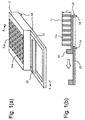
- Figure 1 shows an example of the powder material supply device of the present invention wherein Figure 1(a) is a perspective view thereof and Figure 1(b) is a cross section view taken along the line A-A of Figure 1(a).
- the powder material supply device of the present invention is comprised of a material supplier (charger) 11, a slide plate 12 provided under the material supplier 11, and a base 13.
- each supply opening 11a On the material supplier 11, a large number of supply openings 11a are aligned in a matrix manner with a constant and accurate spacing. Each supply opening 11a penetrates through the material supplier 11 perpendicularly, and the lower end (bottom) of the opening 11a is opened. Since the material supplier 11 has a constant thickness L throughout, each supply opening 11a has a predetermined capacity identical to one another.
- the base 13 is integrally configured with the material supplier 11. However, as shown in Figure 1(b), the base 13 has a large opening right under the material supplier 11. There is a space between the base 13 and the material supplier 11, and the slide plate 12 is slidably provided in the space.
- the slide plate 12 can slide along the space between the base 13 and the material supplier 11 in such a way that it completely closes the bottom of the supply openings 11a of the material supplier 11 as shown in Figure 1(b) or it completely opens all of the bottoms of the supply openings 11a of the material supplier 11 when moving in the direction shown by the arrow of Figure 1(b).
- engagement means such as a plurality of engagement projections 14 are provided at, for example, the bottom corners thereof.
- the engagement projections 14 fit in receptacles (not shown) on the predetermined positions of the lower mold, thereby accurately positioning the powder material supply device relative to the mold system.
- Any other types of engagement means such as grooves, hooks, screws, and etc. are also possible.
- Figure 2 is another embodiment of the powder material supply device in the present invention.
- the material supplier 11 and the supply openings 11a are identical to those in the embodiment of Figure 1.
- this embodiment is characterized in that two slide plates 25 are employed which meet at the center of the space formed between the material supplier 11 and the base 13 and slidably move in the directions opposite to each other. Since the slide plates 25 move toward both sides, the base 26 is also extended toward the both sides.
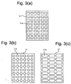
- Figures 3(a)-3(c) show examples of supply openings 11a on the material supplier 11.
- the supply openings in Figure 3(a) have a square shape
- the supply openings in Figure 3(b) have a circular shape
- the supply openings in Figure 3(c) have an ecliptic shape.
- the shape of the supply openings are not limited to the above examples, and can take various other forms such as triangular, polygonal, curved, and/or guitar shapes.
- An example of powder material for the fuel cell separator is prepared by mixing powder of graphite scales (average diameter: 30 ⁇ m) and phenol resin with a weight ratio of between about 100:11 and 100:45, preferably about 100:25.
- the powder material thus formulated is charged in each supply opening 11a of the material supplier 11.
- a flattening rod 15 may be applied in the direction of the arrow on the surface of the material supplier 11 to remove the excessive powder material over the supply openings 11a.
- the powder material of the same and predetermined quantity is filled in each supply opening 11a.
- two (2) kinds of the supply openings 11a a square shape with width of 16mm and a circular shape with diameter of 16mm, are prepared.
- a distance between the supply openings 11a is 3mm.
- the supply openings 11a are aligned in twenty (20) in the row and ten (10) in the column, with a total number of two hundreds.
- the powder material supply device filled with the powder material is set on a lower mold 21 of a press machine as shown in Figure 4(b). Since the lower mold 21 includes receptacles to couple with the engagement means such as the engagement projections 14 on the bottom of the base 13 ( Figure 1(a) and 1(b)), accurate positioning between the powder material supply device and the lower mold 21 can be easily and quickly achieved.
- a pattern 21a for a lower surface of the fuel cell separator is formed on the lower mold 21, while a pattern 22a for an upper surface of the fuel cell separator is formed on an upper mold 22.
- the slide plate 12 is pulled in the direction of the arrow until being stopped by the end of the base 13. Since all the bottom of the supply openings 11a are opened, the powder material filled in the supply openings 11a falls on the pattern 21a on the lower mold 21. Because the plurality of the supply openings 11a are regularly and accurately aligned in a matrix manner and thus the same amount of powder material has been filled in each supply opening 11a, the powder material provided onto the lower mold 21 is distributed evenly, eliminating any unevenness of the material thickness.
- a sample 1 in Table 1 is a powder material supply device having square shaped supply openings 11a of 16mm in width and with the single-side slide type of Figure 1 (type 1).
- a sample 2 is a powder material supply device having the identical conditions as that in the sample 1 except that it uses the double-side slide type shown in Figure 2 (type 2).
- a sample 3 is a powder material supply device of type 1 and has circular shaped supply openings 11a of 16mm in diameter.
- a sample 4 is a powder material supply device of type 2 and has circular shaped supply openings 11a of 16mm in diameter.
- Table 1 also shows the data involving the prior art example, using the same powder material as used in the examples 1-4 described above but without using the powder material supply device of the present invention.
- the powder material is directly filled in the lower mold. All the other conditions including the molding pressure, temperature and the molding time are the same among the examples 1-4 as well as the prior art example.
- the powder material supply device of the present invention by adjusting the number of the supply openings depending on the size of the fuel cell separator, various sizes of fuel cell separator, from a small surface area to a large surface area, can be produced with high surface accuracy or thickness accuracy. Therefore, a fuel cell separator larger than 200mm by 200mmm, which has been difficult to produce under the conventional technology, can be easily achieved with the surface unevenness of less than 0.07mm.
- the application of the powder material supply device of the present invention is not limited to the production of the fuel cell separator.
- the present invention can be applied to anything that requires to evenly distribute powder material into a mold.
- the powder material supply device of the present invention can distribute the powder material equally and accurately to the mold due to the configuration comprising the material supplier having the plurality of supply openings in the downward directions, the slide plate which is slidable between the positions where all the supply openings are closed and where all the openings are opened, and the base for supporting the slide plate and the material supplier.
- the unevenness of the thickness of the separator can be minimized.
- the amount of powder material in each supply opening is identical to one another, thereby minimizing the unevenness of thickness of the final products formed through the mold process of the present invention.
- the powder material supply device of the present invention can be accurately positioned on the press mold.
- the unevenness of the thickness of the separator is minimized.
- the resistance between the fuel cell separator and the gas diffusion electrode can be decreased, thereby increasing the overall efficiency of power generation in the fuel cell.
Landscapes
- Engineering & Computer Science (AREA)
- Chemical & Material Sciences (AREA)
- Mechanical Engineering (AREA)
- Manufacturing & Machinery (AREA)
- Composite Materials (AREA)
- Life Sciences & Earth Sciences (AREA)
- Robotics (AREA)
- Sustainable Development (AREA)
- Sustainable Energy (AREA)
- Chemical Kinetics & Catalysis (AREA)
- Electrochemistry (AREA)
- General Chemical & Material Sciences (AREA)
- Fuel Cell (AREA)
- Processing And Handling Of Plastics And Other Materials For Molding In General (AREA)
- Casting Or Compression Moulding Of Plastics Or The Like (AREA)
Abstract
A powder material supply device is able to supply
powder material to a mold system equally and accurately to
produce a fuel cell separator of high surface accuracy,
thereby producing a high performance fuel cell. The powder
material supply device includes a material supplier which is
provided with a plurality of supply openings in a downward
direction, a slide plate provided at the lower part of the
material supplier and is capable of slidably moving between a
location where all of the supply openings are closed and
another location where all the supply openings are opened,
and a base to support the material supplier and the slide
plate.
Description
- This invention relates to a powder material supply device which is used for producing a predetermined form of objects by supplying powder material to a mold system. This invention also relates to a production method of a fuel cell separator and a fuel cell separator produced by this production method using the powder material supply device. Here, the term "powder material" generally refers to material in the forms of powder, particle and/or short fiber.
- A fuel cell which generates electric power by making use of fuel gas and oxidant gas, especially a solid polymer type fuel cell, is considered to be a new clean energy source in various applications including automobiles. A solid polymer fuel cell is configured in such a way that an ion conductive solid electrolyte membrane is sandwiched by an anode and a cathode each having a catalyst and functioning as a gas diffusion electrode, and an outside of each electrode is further provided with a fuel cell separator. The separator at the anode provides hydrogen as fuel gas, and the separator at the cathode provides oxygen as oxidizer gas.
- Figures 5(a) and 5(b) show an example of such a fuel cell separator. As shown in Figures 5(a) and 5(b), on a
fuel cell separator 1, narrow grooves 1a are formed on a planar surface thereof. In order to increase an overall surface area for contacting between the gas diffusion electrode and the gas, the grooves 1a are meandering with a small pitch on the whole surface of the separator. The grooves 1a may be formed on both surfaces of the separator as shown in Figure 5(b), or may be formed only on one surface of the separator. - There are other types of structures of the separator wherein both surfaces or one surface is provided with a large number of projections where spaces between those projections are used as passages of the gas, or both surfaces or one surface is provided with combinations of such projections and grooves.
- In the fuel cell separator described above, the following characteristics are required.
- (1) Gas non-permeability. This is a characteristic not to allow the hydrogen gas and/or oxygen gas supplied thereto to permeate through the separator. Generally, a fuel cell is formed of many cell units stacked together where each cell unit includes a solid polymer electrolyte membrane at the center, gas diffusion electrodes at both outer sides of the electrolyte membrane, and the separators further outside of both of the electrodes. The gas is flowing at least one side of a separator. Therefore, if the separator has gas permeability or leakage, an overall efficiency of power generation by the fuel cell decreases, or the power generation itself cannot be performed.
- (2) Electric conductivity. Because the separator also acts as an electrode of the fuel cell, electric conductivity is an essential requirement.
- (3) High surface or thickness accuracy. Because electric current flows through the contact area between the separator and the anode or cathode, insufficient surface accuracy, i.e, profile irregularity, deteriorates electric conductivity due to the insufficient contact area. Moreover, when the surface accuracy is insufficient, gaps may be formed between the anode and the cathode, which may cause breakage of the separator when a force is applied to the separator in such a direction to press the gaps. When the surface accuracy is high, the contact resistance is small, resulting in improvement of the fuel cell performance. The surface accuracy is represented by a difference d between the maximum thickness Tmax and the minimum thickness Tmin by measuring the thickness at predetermined points on the separator.
-
- In order to satisfy the requirements noted above, in the conventional technology, the fuel cell separator is produced through a mechanical process such as machine works on a graphite board. However, due to the long processing time, the fuel cell separator becomes too expensive.
- Recently, a production method using a mold technology has been employed for the purpose of producing the fuel cell separators. In this conventional method, powder material is formed by mixing carbon powder in the form of powder and/or short fiber and synthesis resin powder. The resultant powder material is supplied to a lower mold of a mold system such as a press machine which is then covered by an upper mold of the mold system. The fuel cell separator is formed by pressing the powder material by the press machine in the high temperature condition.
- However, the conventional production method using the mold technology described above has a problem in that it is difficult to achieve the sufficient level of surface accuracy of the separator. For example, in this conventional production method, the difference d of the thickness described above tends to be 0.2mm or more, thereby limiting the performance of the fuel cell.
- The present invention reflects on the aforementioned facts, and aims to provide a fuel cell separator which is able to achieve the surface accuracy higher than that of the conventional technology, a production method of the fuel cell separator, and a powder material supply device suited for the production method.
- In order to achieve the objectives above, the powder material supply device of the present invention is characterized in having a material supplier which is provided with a plurality of supply openings in a downward direction, a slide plate provided at the lower part of the material supplier and is capable of slidably moving between a location where all of the supply openings are closed and another location where all the supply openings are opened, and a base to support the material supplier and the slide plate.
- The material supplier has a predetermined constant thickness or height, thereby forming the same capacity for each and every supply opening formed thereon. Preferably, engagement means are provided on the powder material supply device for accurately positioning the powder material supply device on a mold system, such as a lower mold to which the powder material is supplied. The supply openings are aligned on the material supplier equally and accurately in, for example, a matrix manner.
- The production method of the present invention in which a fuel cell separator is formed by supplying the powder material to a lower mold and applying pressure and heat between the upper mold and the lower mold, is characterized in that the powder material for the fuel cell separator is supplied through a plurality of supply openings.
- Further, the production method of the present invention in which a fuel cell separator is formed by supplying the powder material to the lower mold and applying pressure and heat between the upper mold and the lower mold, is characterized in that the powder material supply device having either one slide plate or two slide plates are used for supplying the powder material to the lower mold.
- The fuel cell separator of the present invention is characterized as having a surface accuracy of less than 0.07mm wherein the material of the fuel cell separator is a mixture of carbon powder and synthetic resin powder and the size of the separator is more than 200mm by 200mm.
-
- Figure 1 shows the powder material supply device in the first embodiment of the present invention where Figure 1(a) is a perspective view thereof and Figure 1(b) is a cross section view taken along the A-A line of Figure 1(a).
- Figure 2 is a cross sectional view of the powder material supply device in the second embodiment of the present invention.
- Figures 3(a), 3(b) and 3(c) are top views of the powder material supply device of the present invention showing various shapes of supply openings.
- Figures 4(a)-4(d) are cross sectional diagrams showing a process of producing a fuel cell separator using the powder material supply device of the present invention.
- Figure 5 shows an example of fuel cell separator where Figure 5(a) is a plan view thereof and Figure 5(b) is a cross sectional view taken along the B-B line of Figure 5(a).
-
- The embodiments of the present invention are explained in detail with reference to the accompanying drawings. Figure 1 shows an example of the powder material supply device of the present invention wherein Figure 1(a) is a perspective view thereof and Figure 1(b) is a cross section view taken along the line A-A of Figure 1(a).
- As shown in Figures 1(a) and 1(b), the powder material supply device of the present invention is comprised of a material supplier (charger) 11, a
slide plate 12 provided under thematerial supplier 11, and abase 13. - On the
material supplier 11, a large number ofsupply openings 11a are aligned in a matrix manner with a constant and accurate spacing. Each supply opening 11a penetrates through thematerial supplier 11 perpendicularly, and the lower end (bottom) of the opening 11a is opened. Since thematerial supplier 11 has a constant thickness L throughout, each supply opening 11a has a predetermined capacity identical to one another. - In this example, the
base 13 is integrally configured with thematerial supplier 11. However, as shown in Figure 1(b), thebase 13 has a large opening right under thematerial supplier 11. There is a space between thebase 13 and thematerial supplier 11, and theslide plate 12 is slidably provided in the space. - The
slide plate 12 can slide along the space between thebase 13 and thematerial supplier 11 in such a way that it completely closes the bottom of thesupply openings 11a of thematerial supplier 11 as shown in Figure 1(b) or it completely opens all of the bottoms of thesupply openings 11a of thematerial supplier 11 when moving in the direction shown by the arrow of Figure 1(b). - On the
base 13, engagement means such as a plurality ofengagement projections 14 are provided at, for example, the bottom corners thereof. Theengagement projections 14 fit in receptacles (not shown) on the predetermined positions of the lower mold, thereby accurately positioning the powder material supply device relative to the mold system. Any other types of engagement means, such as grooves, hooks, screws, and etc. are also possible. - Figure 2 is another embodiment of the powder material supply device in the present invention. In this example, the
material supplier 11 and thesupply openings 11a are identical to those in the embodiment of Figure 1. However, this embodiment is characterized in that twoslide plates 25 are employed which meet at the center of the space formed between thematerial supplier 11 and thebase 13 and slidably move in the directions opposite to each other. Since theslide plates 25 move toward both sides, thebase 26 is also extended toward the both sides. - Figures 3(a)-3(c) show examples of
supply openings 11a on thematerial supplier 11. The supply openings in Figure 3(a) have a square shape, and the supply openings in Figure 3(b) have a circular shape, and the supply openings in Figure 3(c) have an ecliptic shape. The shape of the supply openings are not limited to the above examples, and can take various other forms such as triangular, polygonal, curved, and/or guitar shapes. - Referring to Figure 4, the operation of the powder material supply device of the present invention, and accordingly, a production method of the fuel cell separator of the present invention is explained in the following.
- An example of powder material for the fuel cell separator is prepared by mixing powder of graphite scales (average diameter: 30µm) and phenol resin with a weight ratio of between about 100:11 and 100:45, preferably about 100:25.
- In Figure 4(a), the powder material thus formulated is charged in each
supply opening 11a of thematerial supplier 11. A flatteningrod 15 may be applied in the direction of the arrow on the surface of thematerial supplier 11 to remove the excessive powder material over thesupply openings 11a. Thus, the powder material of the same and predetermined quantity is filled in eachsupply opening 11a. In the experiment, two (2) kinds of thesupply openings 11a, a square shape with width of 16mm and a circular shape with diameter of 16mm, are prepared. In each kind of thesupply openings 11a, a distance between thesupply openings 11a is 3mm. Thesupply openings 11a are aligned in twenty (20) in the row and ten (10) in the column, with a total number of two hundreds. - The powder material supply device filled with the powder material is set on a
lower mold 21 of a press machine as shown in Figure 4(b). Since thelower mold 21 includes receptacles to couple with the engagement means such as theengagement projections 14 on the bottom of the base 13 (Figure 1(a) and 1(b)), accurate positioning between the powder material supply device and thelower mold 21 can be easily and quickly achieved. Apattern 21a for a lower surface of the fuel cell separator is formed on thelower mold 21, while apattern 22a for an upper surface of the fuel cell separator is formed on anupper mold 22. - In Figure 4(c), the
slide plate 12 is pulled in the direction of the arrow until being stopped by the end of thebase 13. Since all the bottom of thesupply openings 11a are opened, the powder material filled in thesupply openings 11a falls on thepattern 21a on thelower mold 21. Because the plurality of thesupply openings 11a are regularly and accurately aligned in a matrix manner and thus the same amount of powder material has been filled in eachsupply opening 11a, the powder material provided onto thelower mold 21 is distributed evenly, eliminating any unevenness of the material thickness. - Then, as shown in Figure 4(d), the
upper mold 22 is placed on thelower mold 21, and a fuel cell separator with a size of 400mm x 200mm is produced in the mold temperature of 160 degrees centigrade and molding pressure of 200kg/cm2, and with the molding time of 5 minuets. The thickness is measured at predetermined forty (40) points of the fuel cell separator produced in the foregoing. The difference d between the maximum thickness Tmax and the minimum thickness Tmin, that is,Shape of Openings Supply Device Type T Sample 1 16mm square Type 1 0.05mm Sample 2 16mm square Type 2 0.06mm Sample 3 16mm circle Type 1 0.06mm Sample 4 16mm circle Type 2 0.07mm Prior Art 0.3mm - The results of the experiment is summarized in Table 1 above. A
sample 1 in Table 1 is a powder material supply device having square shapedsupply openings 11a of 16mm in width and with the single-side slide type of Figure 1 (type 1). A sample 2 is a powder material supply device having the identical conditions as that in thesample 1 except that it uses the double-side slide type shown in Figure 2 (type 2). A sample 3 is a powder material supply device oftype 1 and has circular shapedsupply openings 11a of 16mm in diameter. A sample 4 is a powder material supply device of type 2 and has circular shapedsupply openings 11a of 16mm in diameter. - Table 1 also shows the data involving the prior art example, using the same powder material as used in the examples 1-4 described above but without using the powder material supply device of the present invention. Thus, in the prior art example, the powder material is directly filled in the lower mold. All the other conditions including the molding pressure, temperature and the molding time are the same among the examples 1-4 as well as the prior art example. The fuel cell separators of the identical outer size are formed, and the thickness of each separator is measured at 40 points as noted above. The difference d between the maximum thickness Tmax and the minimum thickness Tmin, that is,
- As apparent from the data in Table 1, although the unevenness of thickness which is expressed by the difference d is 0.3mm in the prior art, the unevenness is improved to less than 0.07mm when using the powder material supply device of the present invention.
- In the powder material supply device of the present invention, by adjusting the number of the supply openings depending on the size of the fuel cell separator, various sizes of fuel cell separator, from a small surface area to a large surface area, can be produced with high surface accuracy or thickness accuracy. Therefore, a fuel cell separator larger than 200mm by 200mmm, which has been difficult to produce under the conventional technology, can be easily achieved with the surface unevenness of less than 0.07mm.
- The application of the powder material supply device of the present invention is not limited to the production of the fuel cell separator. The present invention can be applied to anything that requires to evenly distribute powder material into a mold.
- As described in the forgoing, the powder material supply device of the present invention can distribute the powder material equally and accurately to the mold due to the configuration comprising the material supplier having the plurality of supply openings in the downward directions, the slide plate which is slidable between the positions where all the supply openings are closed and where all the openings are opened, and the base for supporting the slide plate and the material supplier. Thus, the unevenness of the thickness of the separator can be minimized.
- Since the material supplier has the same predetermined height and shape of the supply openings, the amount of powder material in each supply opening is identical to one another, thereby minimizing the unevenness of thickness of the final products formed through the mold process of the present invention.
- Further, since the engagement projections for positioning the powder material supply device with respect to the mold are provided to fit in the receptacles on the mold, the powder material supply device of the present invention can be accurately positioned on the press mold.
- In the fuel cell separator formed through the mold process using the powder material supply device of the present invention, the unevenness of the thickness of the separator is minimized. Thus, the resistance between the fuel cell separator and the gas diffusion electrode can be decreased, thereby increasing the overall efficiency of power generation in the fuel cell.
- Although only a preferred embodiment is specifically illustrated and described herein, it will be appreciated that many modifications and variations of the present invention are possible in light of the above teachings and within the purview of the appended claims without departing the spirit and intended scope of the invention.
Claims (12)
- A powder material supply device for supplying powder material to a mold system, comprising:a material supplier which is provided with a plurality of supply openings in a downward direction for downwardly supplying powder material;a slide plate provided at a lower portion of the material supplier and is capable of slidably moving between a first location where all of the supply openings are closed and second location where all the supply openings are opened, and;a base to support the material supplier and the slide plate.
- A powder material supply device as defined in Claim 1, wherein said slide plate is comprised of a single plate which is slidable in a horizontal direction between said first location and said second location.
- A powder material supply device as defined in Claim 1, wherein said slide plate is comprised of two plates each being slidable in a horizontal direction which is opposite to each other between said first location and said second location.
- A powder material supply device as defined in Claim 1, wherein said material supplier has a predetermined constant thickness, thereby forming the same capacity for each and every supply opening formed on said material supplier.
- A powder material supply device as defined in Claim 1, wherein said material supplier has an engagement means for accurately positioning the powder material supply device on the mold system to which the powder material is supplied.
- A powder material supply device as defined in Claim 1, wherein said supply openings are aligned on the material supplier equally and accurately in a matrix manner.
- A powder material supply device as defined in Claim 1, wherein said supply openings are aligned on the material supplier equally and accurately in a matrix manner and wherein each of said supply openings has a shape and size identical to one another.
- A powder material supply device as defined in Claim 1, wherein said powder material is material for forming a separator of a fuel cell.
- A powder material supply device as defined in Claim 1, wherein said powder material is a mixture of carbon and synthetic resin in forms of powder, particle and/or short fiber with weight ratio between about 100:11 and 100:45 for forming a separator of a fuel cell.
- A powder material supply device as defined in Claim 1, wherein said powder material is a mixture of carbon and synthetic resin in forms of powder, particle and/or short fiber with weight ratio of about 100:25 for forming a separator of a fuel cell.
- A method for producing a fuel cell separator with use of a mold system having an upper mold and a lower mold by supplying powder material to the lower mold and applying pressure and heat between the upper mold and the lower mold, wherein the method provides the powder material for the fuel cell separator through a plurality of supply openings each being oriented in a downward direction and having a capacity identical to one another.
- A fuel cell separator formed through a mold process and made of powder material which is a mixture of carbon powder and synthetic resin powder wherein said fuel cell separator has a surface accuracy of less than 0.07mm and a size of greater than 200mm by 200mm.
Applications Claiming Priority (2)
| Application Number | Priority Date | Filing Date | Title |
|---|---|---|---|
| JP24150899 | 1999-08-27 | ||
| JP24150899A JP3356728B2 (en) | 1999-08-27 | 1999-08-27 | Apparatus for charging powdery raw material for fuel cell separator, method for manufacturing fuel cell separator, and fuel cell separator |
Publications (1)
| Publication Number | Publication Date |
|---|---|
| EP1078725A2 true EP1078725A2 (en) | 2001-02-28 |
Family
ID=17075384
Family Applications (1)
| Application Number | Title | Priority Date | Filing Date |
|---|---|---|---|
| EP00117386A Withdrawn EP1078725A2 (en) | 1999-08-27 | 2000-08-24 | Powder material supply device, method of producing fuel cell separator, and fuel cell separator formed by this production method |
Country Status (4)
| Country | Link |
|---|---|
| US (1) | US6397901B1 (en) |
| EP (1) | EP1078725A2 (en) |
| JP (1) | JP3356728B2 (en) |
| CA (1) | CA2316635A1 (en) |
Cited By (6)
| Publication number | Priority date | Publication date | Assignee | Title |
|---|---|---|---|---|
| EP1315222A1 (en) * | 2001-11-21 | 2003-05-28 | Araco Kabushiki Kaisha | Conductive plate molding method and molding apparatus |
| US6663819B2 (en) | 2001-11-21 | 2003-12-16 | Araco Kabushiki Kaisha | Conductive plate molding method |
| CN106142420A (en) * | 2016-08-15 | 2016-11-23 | 浙江铭泰汽车零部件有限公司 | It is easy to the brake block heat pressing forming machines of feeding |
| CN106273165A (en) * | 2016-08-15 | 2017-01-04 | 浙江铭泰汽车零部件有限公司 | A kind of brake block heat pressing forming machines |
| WO2024062447A1 (en) * | 2022-09-23 | 2024-03-28 | Sacmi Cooperativa Meccanici Imola Societa' Cooperativa | Apparatus and method for making moulded products |
| RU2850276C2 (en) * | 2022-09-23 | 2025-11-07 | Сакми Кооператива Мекканичи Имола Сочиета' Кооператива | Device and method for manufacturing moulded products |
Families Citing this family (13)
| Publication number | Priority date | Publication date | Assignee | Title |
|---|---|---|---|---|
| WO2002086427A1 (en) * | 2001-04-20 | 2002-10-31 | Glaxo Group Limited | Metering method for particulate material |
| JP4593836B2 (en) * | 2001-07-09 | 2010-12-08 | 本田技研工業株式会社 | Separator molding material input method |
| JP2006140027A (en) * | 2004-11-12 | 2006-06-01 | Matsui Mfg Co | Manufacturing apparatus and manufacturing method for fuel cell separator |
| JP4658969B2 (en) * | 2004-12-17 | 2011-03-23 | 株式会社松井製作所 | Method and apparatus for filling granular material in compression molding process |
| JP5138154B2 (en) | 2005-03-07 | 2013-02-06 | 日清紡ホールディングス株式会社 | Manufacturing method of fuel cell separator |
| JP4469755B2 (en) * | 2005-05-23 | 2010-05-26 | 株式会社松井製作所 | Powder material filling equipment in compression molding |
| JP4953619B2 (en) * | 2005-11-04 | 2012-06-13 | Towa株式会社 | Resin sealing molding equipment for electronic parts |
| US20090311356A1 (en) * | 2008-06-13 | 2009-12-17 | Belt James S | Dosing Apparatus |
| JP5424637B2 (en) * | 2008-12-26 | 2014-02-26 | 信越ポリマー株式会社 | Manufacturing method of fuel cell separator |
| JP2010247429A (en) * | 2009-04-15 | 2010-11-04 | Apic Yamada Corp | Resin sealing apparatus and resin sealing method using the same |
| JP6333761B2 (en) * | 2015-03-31 | 2018-05-30 | Towa株式会社 | Resin material supply method and supply device for compression molding apparatus, compression molding method and compression molding apparatus |
| JP6017634B1 (en) * | 2015-06-10 | 2016-11-02 | Towa株式会社 | Resin material supply device and method for compression molding apparatus, compression molding apparatus, and resin molded product manufacturing method |
| JP6349376B2 (en) * | 2016-12-07 | 2018-06-27 | Towa株式会社 | Resin material supply apparatus and method for compression molding apparatus, and compression molding apparatus and resin molded product manufacturing method |
Family Cites Families (12)
| Publication number | Priority date | Publication date | Assignee | Title |
|---|---|---|---|---|
| US1139269A (en) * | 1914-03-30 | 1915-05-11 | Goodman & Sons A | Measuring-machine. |
| US1488603A (en) * | 1920-08-19 | 1924-04-01 | Winchester Repeating Arms Co | Device for dispensing fluid material or the like |
| US3380633A (en) * | 1967-01-16 | 1968-04-30 | Vern F. Du Bois | Multiple cavity gunpowder dispenser |
| US3718164A (en) * | 1971-11-17 | 1973-02-27 | Allied Chem | Powder feeding device |
| US3987824A (en) * | 1975-01-27 | 1976-10-26 | Zehnder Fred W | Water glass filler |
| US4143688A (en) * | 1977-02-14 | 1979-03-13 | Gill Jr Robert E | Apparatus for selectively dispensing pasty substances |
| NL8003949A (en) * | 1980-07-09 | 1982-02-01 | Electrochem Energieconversie | METHOD FOR MANUFACTURING A COAT OF AN ELECTRODE FOR A CELL, IN PARTICULAR FOR A FUEL CELL. |
| US4398578A (en) * | 1981-04-16 | 1983-08-16 | The United States Of America As Represented By The Secretary Of Agriculture | Distributor for gravel and seeds |
| JP2725705B2 (en) * | 1988-12-02 | 1998-03-11 | 日清紡績株式会社 | Cell separator for fuel cells |
| JPH0421072A (en) * | 1990-05-15 | 1992-01-24 | Toshiba Corp | Logic circuit design system |
| JP3773325B2 (en) * | 1997-03-17 | 2006-05-10 | ジャパンゴアテックス株式会社 | Gas diffusion layer material for polymer electrolyte fuel cell and its joined body |
| EP1035608A3 (en) * | 1999-02-09 | 2003-02-05 | Nisshinbo Industries, Inc. | Separator for fuel cell and solid polymer type fuel cell using said separator |
-
1999
- 1999-08-27 JP JP24150899A patent/JP3356728B2/en not_active Expired - Lifetime
-
2000
- 2000-08-24 EP EP00117386A patent/EP1078725A2/en not_active Withdrawn
- 2000-08-25 US US09/649,705 patent/US6397901B1/en not_active Expired - Lifetime
- 2000-08-25 CA CA002316635A patent/CA2316635A1/en not_active Abandoned
Cited By (6)
| Publication number | Priority date | Publication date | Assignee | Title |
|---|---|---|---|---|
| EP1315222A1 (en) * | 2001-11-21 | 2003-05-28 | Araco Kabushiki Kaisha | Conductive plate molding method and molding apparatus |
| US6663819B2 (en) | 2001-11-21 | 2003-12-16 | Araco Kabushiki Kaisha | Conductive plate molding method |
| CN106142420A (en) * | 2016-08-15 | 2016-11-23 | 浙江铭泰汽车零部件有限公司 | It is easy to the brake block heat pressing forming machines of feeding |
| CN106273165A (en) * | 2016-08-15 | 2017-01-04 | 浙江铭泰汽车零部件有限公司 | A kind of brake block heat pressing forming machines |
| WO2024062447A1 (en) * | 2022-09-23 | 2024-03-28 | Sacmi Cooperativa Meccanici Imola Societa' Cooperativa | Apparatus and method for making moulded products |
| RU2850276C2 (en) * | 2022-09-23 | 2025-11-07 | Сакми Кооператива Мекканичи Имола Сочиета' Кооператива | Device and method for manufacturing moulded products |
Also Published As
| Publication number | Publication date |
|---|---|
| US6397901B1 (en) | 2002-06-04 |
| JP2001062858A (en) | 2001-03-13 |
| CA2316635A1 (en) | 2001-02-27 |
| JP3356728B2 (en) | 2002-12-16 |
Similar Documents
| Publication | Publication Date | Title |
|---|---|---|
| EP1078725A2 (en) | Powder material supply device, method of producing fuel cell separator, and fuel cell separator formed by this production method | |
| US7285353B2 (en) | PEM fuel cell separator plate | |
| EP2475036B1 (en) | Membrane electrode assembly, production method for same, and fuel cell | |
| US6878480B2 (en) | Electrochemical apparatus with reactant micro-channels | |
| CA2323167C (en) | Separator for a fuel cell | |
| US8354203B2 (en) | Bipolar plate for fuel cells | |
| GB2158286A (en) | Fuel cell electrode substrates | |
| US8192856B2 (en) | Flow field | |
| US20050277013A1 (en) | Solid polymer type fuel cell, metal separator for fuel cell, and kit for fuel cell | |
| US20200075968A1 (en) | Collector plate and redox flow battery | |
| US20140234747A1 (en) | Fuel cell stack | |
| US20030194595A1 (en) | Flow field plate assembly for an electrochemical fuel cell | |
| CN108461796B (en) | Fuel cell end plate unit and cell stack | |
| US20190393534A1 (en) | Collector plate and redox flow battery | |
| US20260088314A1 (en) | Bipolar flow field plate for fuel cells | |
| KR101380401B1 (en) | Hybrid bipolar plate for fuel cell | |
| WO2001082399A1 (en) | Conductance enhancement microstructures for bipolar plates | |
| US20040009386A1 (en) | Gas distributor for fuel cells | |
| US6861172B2 (en) | Current-collecting structure in fuel cell system | |
| JP2006331768A (en) | Polymer electrolyte fuel cell | |
| KR20070094132A (en) | Separator for fuel cell and fuel cell stack comprising same | |
| KR20070094130A (en) | Separator for fuel cell and fuel cell stack comprising same |
Legal Events
| Date | Code | Title | Description |
|---|---|---|---|
| PUAI | Public reference made under article 153(3) epc to a published international application that has entered the european phase |
Free format text: ORIGINAL CODE: 0009012 |
|
| AK | Designated contracting states |
Kind code of ref document: A2 Designated state(s): AT BE CH CY DE DK ES FI FR GB GR IE IT LI LU MC NL PT SE |
|
| AX | Request for extension of the european patent |
Free format text: AL;LT;LV;MK;RO;SI |
|
| STAA | Information on the status of an ep patent application or granted ep patent |
Free format text: STATUS: THE APPLICATION IS DEEMED TO BE WITHDRAWN |
|
| 18D | Application deemed to be withdrawn |
Effective date: 20030301 |