EP1078676A2 - Nitrogen system for regenerating chemical solvent - Google Patents
Nitrogen system for regenerating chemical solvent Download PDFInfo
- Publication number
- EP1078676A2 EP1078676A2 EP00117560A EP00117560A EP1078676A2 EP 1078676 A2 EP1078676 A2 EP 1078676A2 EP 00117560 A EP00117560 A EP 00117560A EP 00117560 A EP00117560 A EP 00117560A EP 1078676 A2 EP1078676 A2 EP 1078676A2
- Authority
- EP
- European Patent Office
- Prior art keywords
- chemical solvent
- column
- gas
- stripping
- acid gas
- Prior art date
- Legal status (The legal status is an assumption and is not a legal conclusion. Google has not performed a legal analysis and makes no representation as to the accuracy of the status listed.)
- Granted
Links
Images


Classifications
-
- B—PERFORMING OPERATIONS; TRANSPORTING
- B01—PHYSICAL OR CHEMICAL PROCESSES OR APPARATUS IN GENERAL
- B01J—CHEMICAL OR PHYSICAL PROCESSES, e.g. CATALYSIS OR COLLOID CHEMISTRY; THEIR RELEVANT APPARATUS
- B01J20/00—Solid sorbent compositions or filter aid compositions; Sorbents for chromatography; Processes for preparing, regenerating or reactivating thereof
- B01J20/30—Processes for preparing, regenerating, or reactivating
-
- B—PERFORMING OPERATIONS; TRANSPORTING
- B01—PHYSICAL OR CHEMICAL PROCESSES OR APPARATUS IN GENERAL
- B01D—SEPARATION
- B01D53/00—Separation of gases or vapours; Recovering vapours of volatile solvents from gases; Chemical or biological purification of waste gases, e.g. engine exhaust gases, smoke, fumes, flue gases, aerosols
- B01D53/14—Separation of gases or vapours; Recovering vapours of volatile solvents from gases; Chemical or biological purification of waste gases, e.g. engine exhaust gases, smoke, fumes, flue gases, aerosols by absorption
- B01D53/1425—Regeneration of liquid absorbents
-
- B—PERFORMING OPERATIONS; TRANSPORTING
- B01—PHYSICAL OR CHEMICAL PROCESSES OR APPARATUS IN GENERAL
- B01D—SEPARATION
- B01D15/00—Separating processes involving the treatment of liquids with solid sorbents; Apparatus therefor
-
- B—PERFORMING OPERATIONS; TRANSPORTING
- B01—PHYSICAL OR CHEMICAL PROCESSES OR APPARATUS IN GENERAL
- B01D—SEPARATION
- B01D2257/00—Components to be removed
- B01D2257/30—Sulfur compounds
- B01D2257/304—Hydrogen sulfide
-
- B—PERFORMING OPERATIONS; TRANSPORTING
- B01—PHYSICAL OR CHEMICAL PROCESSES OR APPARATUS IN GENERAL
- B01D—SEPARATION
- B01D2257/00—Components to be removed
- B01D2257/50—Carbon oxides
- B01D2257/504—Carbon dioxide
-
- Y—GENERAL TAGGING OF NEW TECHNOLOGICAL DEVELOPMENTS; GENERAL TAGGING OF CROSS-SECTIONAL TECHNOLOGIES SPANNING OVER SEVERAL SECTIONS OF THE IPC; TECHNICAL SUBJECTS COVERED BY FORMER USPC CROSS-REFERENCE ART COLLECTIONS [XRACs] AND DIGESTS
- Y02—TECHNOLOGIES OR APPLICATIONS FOR MITIGATION OR ADAPTATION AGAINST CLIMATE CHANGE
- Y02C—CAPTURE, STORAGE, SEQUESTRATION OR DISPOSAL OF GREENHOUSE GASES [GHG]
- Y02C20/00—Capture or disposal of greenhouse gases
- Y02C20/40—Capture or disposal of greenhouse gases of CO2
Definitions
- This invention relates generally to the use of chemical solvent for the removal of acid gas from a process stream, and the subsequent regeneration of the chemical solvent so that it could be reused for further acid gas removal.
- regenerable chemical solvents to remove acid gases from product streams or other process streams.
- chemical solvents are regenerated for reuse utilizing steam as a stripping agent and as a source of heat for the endothermic chemical reactions.
- Such regeneration systems while effective, are energy intensive.
- a method for regenerating a chemical solvent comprising:
- Another aspect of the invention is:
- Apparatus for regenerating a chemical solvent comprising:
- column means a contacting column or zone wherein liquid and vapor phases are countercurrently contacted to effect separation of a fluid mixture, as for example, by contacting of the vapor and liquid phases on a series of vertically spaced trays or plates mounted within the column and/or on packing elements such as structured or random packing.
- absorption column means a column wherein suitable chemical solvent selectively absorbs acid gas from a gas mixture.
- stripping column means a column wherein mass exchange between liquid and gas phases dominates relative to chemical reactions, and results in selective mass transfer of a more volatile component of a downflowing liquid mixture into an upflowing vapor.
- regeneration column means a column wherein simultaneous liquid phase reactions and mass exchange between liquid and gas phases result in the regeneration of acid gas loaded chemical solvent.
- nitrogen gas means a fluid comprising at least 95 mole percent nitrogen on a dry basis.
- upper portion and lower portion mean those sections of a column respectively above and below the mid point of the column.
- indirect heat exchange means the bringing of two fluids into heat exchange relation without any physical contact or intermixing of the fluids with each other.
- the term "reboiler” means a device which generates column upflow vapor from column liquid.
- acid gas means a gas that dissolves in water producing an acidic solution.
- chemical solvent means a solvent that selectively removes acid from a gaseous mixture by adsorption with reaction with a chemical base present in the solvent.
- the invention comprises an arrangement whereby nitrogen gas can be used effectively to separate acid gas from chemical solvent to produce clean chemical solvent.
- nitrogen gas By employing nitrogen gas in this manner, energy intensive steps, such as steam stripping and heating of the acid gas loaded solvent, can be reduced or eliminated.
- feed gas comprising acid gas is passed in stream 1 into the lower portion of absorption column 100.
- this feed gas will be at a pressure within the range of from 50 to 1500 psia and at a temperature of from ambient, e.g. 70°F, to about 260°F.
- the acid gas will comprise from about 1 to 30 mole percent of the composition of the gas in stream 1 passed into column 100.
- the feed gas contains acid gas with mixtures of ethylene, ethane, methane, oxygen, nitrogen, argon and water vapor.
- Acid gas is carbon dioxide.
- the feed gas contains acid gas with mixtures of hydrocarbons, hydrogen, nitrogen and water vapor.
- Acid gas is hydrogen sulfide or carbon dioxide or mixtures thereof.
- natural gas treating processes the feed gas contains acid gas with mixtures of hydrocarbons, nitrogen and water vapor.
- Acid gas is hydrogen sulfide or carbon dioxide or mixtures thereof.
- the feed gas from gasification of coal, oil, petroleum coke and gaseous fuels contains acid gas, with mixtures of hydrogen, carbon monoxide, nitrogen, argon, and water vapor.
- the acid gas is carbon dioxide or hydrogen sulfide or mixtures thereof.
- this feed gas is treated with a chemical solvent passed into the upper portion of absorption column 100 in stream 12.
- chemical solvents which may be used in the practice of this invention one can name alkali salt solutions such as sodium carbonate solution and potassium carbonate solution, ethanolamines such as monoethanol amine (MEA), diethanol amine (DEA), methyldiethanol amine (MDEA) and the like.
- the chemical solvents could also contain other chemicals: (a) functioning as catalysts to promote the rate of absorption, (b) functioning as inhibitors to prevent chemical solvent degradation, (c) functioning as corrosion inhibitors.
- the optimal choice of chemical solvent depends on the feed gas composition, feed gas pressure, and specifications on the acid gas concentration in the treated gas.
- gas in stream 1 comprises ethylene, ethane, methane, oxygen, nitrogen and water vapor, and the acid gas is carbon dioxide, at a pressure generally within the range of from 50 to 500 pounds per square inch absolute (psia) and at a temperature generally within the range of from ambient temperature to 240°F.
- psia pounds per square inch absolute
- Chemical solvent is passed into the upper portion of absorption column 100 in stream 12.
- the chemical solvent in stream 12 is potassium carbonate in solution, generally from 15 to 40 weight percent, more typically from 20 to 30 weight percent, and at an elevated temperature, generally within the range of from 80°F to 260°F, preferably from 100°F to 200°F.
- the cleaned feed gas is withdrawn from the upper portion of absorption column 100 in stream 2 for recovery.
- carbon dioxide dissolves in the potassium carbonate solution during the countercurrent flowing within column 100, forms carbonic acid, which then reacts with the potassium carbonate to form potassium bicarbonate.
- the extent of conversion of potassium carbonate to potassium bicarbonate is governed by ionic reactions chemical equilibrium.
- the resulting potassium bicarbonate rich solution is the loaded chemical solvent. This process is exothermic and results in a temperature rise within absorption column 100.
- the resulting hot potassium bicarbonate rich solution is withdrawn from the lower portion of absorption column 100 in stream 3, reduced in pressure by passage through pressure let down valve 101 and then in stream 4 is passed into the upper portion of regeneration column 102.
- Regeneration column 102 is operating at a pressure generally within the range of from 2 to 50 pounds per square inch gauge (psig), preferably within the range of from 5 to 10 psig.
- psig pounds per square inch gauge
- the partially loaded chemical solvent collecting in the sump of column 102 is passed in line 20 to reboiler 6 wherein it is heated by indirect heat exchange with a process fluid such as steam at a pressure less than 150 psig, preferably at a pressure of about 30 psig.
- the heated partially loaded chemical solvent is then returned to column 102 in stream 21 thereby providing heat to the lower portion of column 102.
- the heating of the potassium bicarbonate solution results in the conversion of the potassium bicarbonate to potassium carbonate and also results in the boiling of some of the liquid water to water vapor for upflow through column 102 as rising vapor.
- the heated partially loaded chemical solvent e.g. potassium carbonate and potassium bicarbonate solution with carbon dioxide dissolved therein
- stripping column 107 which typically has from 2 to 10 theoretical equilibrium stages, preferably from 2 to 5 theoretical equilibrium stages.
- Nitrogen gas is passed in stream 7 into the lower portion of stripping column 107.
- the nitrogen gas is typically at a temperature within the range of from 70 to 250 °F and at a pressure typically within the range of from 5 to 50 psig, preferably from 10 to 30 psig.
- the flow rate of nitrogen gas corresponds to 0.5 to 3 pound moles, preferably 1 to 2 pound moles, of nitrogen per pound mole of carbon dioxide in the feed gas.
- the nitrogen gas may be from an air separation plant such as a cryogenic air separation plant, or an air separation plant employing adsorption or membrane technology.
- the nitrogen gas is from a cryogenic air separation plant which also produces oxygen which is employed in another operation of the overall plant, such as for chemical oxidation or combustion purposes.
- stripping column 107 the downwardly flowing heated partially loaded chemical solvent flows in countercurrent mass transfer contact with upwardly flowing nitrogen gas and in doing so acid gas, e.g. carbon dioxide, is stripped out from the solvent into the nitrogen gas to produce acidified stripping gas in the upper portion of stripping column 107 and regenerated chemical solvent in the lower portion of stripping column 107.
- acid gas e.g. carbon dioxide
- the regenerated chemical solvent is withdrawn from the lower portion of stripping column 107 in stream 22 and recovered.
- additional chemical solvent, make-up chemical solvent, in stream 11 is combined with all or a portion of stream 22 to form stream 23 which is pumped through pump 105 to form stream 12 which is passed into absorption column 100 for use as previously described. In this way the regenerated chemical solvent produced by the invention finds reuse directly within the system.
- the acidified stripping gas comprising mostly nitrogen and acid gas, is passed from the upper portion of stripping column 107 in stream 24 into the lower portion of regeneration column 102 and then up column 102 as rising vapor in contact with downflowing partially loaded chemical solvent.
- the rising vapors within column 102 collect in the upper portion of column 102 and are withdrawn therefrom in steam 9 which comprises mostly nitrogen, water vapor and acid gas.
- Stream 9 is cooled in cooler 25 by indirect heat exchange with a cooling fluid, e.g. cooling water, and at least a portion of the water vapor is condensed.
- Resulting two phase stream 26 is passed to phase separator 27 wherein it is separated into a vapor portion, which is removed from the system in stream 10, and into a liquid portion which is returned to column 102 in stream 28.
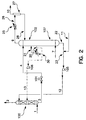
- Figure 2 illustrates another preferred embodiment of the invention wherein the stripping column and the regeneration column are combined and encased in a single piece of hardware.
- the method of operation of the embodiment illustrated in Figure 2 is similar to that of the embodiment illustrated in Figure 1 and will not be described again in detail.
- the numerals of Figure 2 are the same as those of Figure 1 for the common elements.
- FIG. 2 shows one process difference from that illustrated in Figure 1 in that optionally a portion 30 of partially loaded chemical solvent stream 20 is not passed to reboiler 6 but, rather, is pumped by passage through pump 106 to a higher pressure and then passed as stream 13 at an intermediate level into absorption column 100 for downflow therein, resulting in additional countercurrent mass transfer flow with upflowing acid gas containing feed gas.
- Figure 3 illustrates another preferred embodiment of the invention wherein nitrogen supplied through line 7 is first used as motive fluid to ejector 104, which is in contact with a flash drum 103.
- the method of operation of the embodiment illustrated in Figure 3 to regenerate dirty solvent into clean solvent is similar to that of the embodiments illustrated in Figures 1 and 2, and will not be described in detail.
- the numerals in Figure 3 are the same as those in Figures 1 and 2 for the common elements.
- the embodiment illustrated in Figure 3 results in vaporization of a portion of water in the regenerated chemical solvent, and an increase in the flow rate of stripping gas enabling more thorough desorption of acid gas from the downflowing liquid mixture.
- the solvent in stream 22 first passes to drum 103 and then from drum 103 in stream 40 for combination with stream 11.
Abstract
Description
Claims (10)
- A method for regenerating a chemical solvent comprising:(A) contacting feed gas comprising acid gas with chemical solvent, and passing acid gas from the feed gas into the chemical solvent to produce loaded chemical solvent;(B) flash vaporizing some of the acid gas from the loaded chemical solvent to produce partially loaded chemical solvent, and heating the partially loaded chemical solvent to produce heated partially loaded chemical solvent.(C) passing the heated partially loaded chemical solvent in countercurrent mass transfer contact with nitrogen gas and stripping acid gas from the heated partially loaded chemical solvent into the nitrogen gas to produce acidified stripping gas and regenerated chemical solvent;(D) passing acidified stripping gas in contact with the partially loaded chemical solvent; and(E) recovering regenerated chemical solvent.
- The method of claim 1 further comprising contacting recovered regenerated chemical solvent with feed gas comprising acid gas.
- The method of claim 1 further comprising contacting partially loaded chemical solvent with feed gas comprising acid gas.
- The method of claim 1 wherein the partially loaded chemical solvent is heated by indirect heat exchange with steam.
- The method of claim 1 wherein the acid gas comprises carbon dioxide.
- The method of claim 1 wherein the chemical solvent comprises a solution of potassium carbonate and water.
- Apparatus for regenerating a chemical solvent comprising:(A) an absorption column, means for passing feed gas comprising acid gas into the lower portion of the absorption column, and means for passing chemical solvent into the upper portion of the absorption column;(B) a regeneration column, means for passing fluid from the lower portion of the absorption column to the upper portion of the regeneration column, and means for providing heat to the regeneration column;(C) a stripping column, means for passing fluid from the lower portion of the regeneration column into the stripping column, and means for providing nitrogen gas into the stripping column;(D) means for passing fluid from the upper portion of the stripping column into the regeneration column; and(E) means for recovering regenerated chemical solvent from the lower portion of the stripping column.
- The apparatus of claim 7 further comprising means for passing fluid from the stripping column to the absorption column.
- The apparatus of claim 7 further comprising means for passing fluid from the regeneration column to the absorption column.
- The apparatus of claim 7 wherein the stripping column and the regeneration column are housed together in a unitary element.
Applications Claiming Priority (2)
| Application Number | Priority Date | Filing Date | Title |
|---|---|---|---|
| US09/375,482 US6174348B1 (en) | 1999-08-17 | 1999-08-17 | Nitrogen system for regenerating chemical solvent |
| US375482 | 1999-08-17 |
Publications (3)
| Publication Number | Publication Date |
|---|---|
| EP1078676A2 true EP1078676A2 (en) | 2001-02-28 |
| EP1078676A3 EP1078676A3 (en) | 2001-08-22 |
| EP1078676B1 EP1078676B1 (en) | 2003-06-04 |
Family
ID=23481059
Family Applications (1)
| Application Number | Title | Priority Date | Filing Date |
|---|---|---|---|
| EP00117560A Expired - Lifetime EP1078676B1 (en) | 1999-08-17 | 2000-08-15 | Acid gas removal by a chemical solvent regenerated with nitrogen |
Country Status (6)
| Country | Link |
|---|---|
| US (1) | US6174348B1 (en) |
| EP (1) | EP1078676B1 (en) |
| KR (1) | KR20010070022A (en) |
| BR (1) | BR0003582A (en) |
| CA (1) | CA2316136A1 (en) |
| DE (1) | DE60003123T2 (en) |
Cited By (3)
| Publication number | Priority date | Publication date | Assignee | Title |
|---|---|---|---|---|
| WO2013166301A1 (en) * | 2012-05-02 | 2013-11-07 | Mecs, Inc. | Regenerative recovery of contaminants from effluent gases |
| US9266059B2 (en) | 2013-03-15 | 2016-02-23 | Mecs, Inc. | Regenerative recovery of contaminants from effluent gases |
| EP3318314A1 (en) * | 2016-11-04 | 2018-05-09 | Linde Aktiengesellschaft | Method and installation for cleaning a gas |
Families Citing this family (10)
| Publication number | Priority date | Publication date | Assignee | Title |
|---|---|---|---|---|
| CN101340958B (en) * | 2005-12-19 | 2011-04-13 | 氟石科技公司 | Integrated compressor/stripper configurations and methods |
| WO2009009594A1 (en) * | 2007-07-09 | 2009-01-15 | Chart Industries, Inc. | Plate fin fluid processing device |
| CN101970079B (en) * | 2008-02-18 | 2013-09-04 | 氟石科技公司 | Regenerator configurations and methods with reduced steam demand |
| US7935178B2 (en) * | 2008-03-26 | 2011-05-03 | Uop Llc | Use of a biphasic turbine in a process for recovering energy in gasification and natural gas applications |
| CA2787146C (en) | 2010-02-17 | 2016-05-17 | Fluor Technologies Corporation | Configurations and methods of high pressure acid gas removal in the production of ultra-low sulfur gas |
| US8641812B2 (en) * | 2010-05-17 | 2014-02-04 | General Electric Company | Gas treatment and solar thermal collection system |
| SG10201505209UA (en) * | 2010-07-02 | 2015-08-28 | Exxonmobil Upstream Res Co | Low emission power generation systems and methods |
| JP5707894B2 (en) * | 2010-11-22 | 2015-04-30 | 株式会社Ihi | Carbon dioxide recovery method and recovery apparatus |
| US9671162B2 (en) | 2012-10-24 | 2017-06-06 | Fluor Technologies Corporation | Integration methods of gas processing plant and nitrogen rejection unit for high nitrogen feed gases |
| DE102014018844A1 (en) * | 2014-12-17 | 2016-06-23 | Linde Aktiengesellschaft | Process and apparatus for detergent regeneration in a physical gas scrubber |
Citations (7)
| Publication number | Priority date | Publication date | Assignee | Title |
|---|---|---|---|---|
| GB1292122A (en) * | 1968-10-15 | 1972-10-11 | Vetrocoke Cokapuania Spa | Improvements in or relating to the treatment of gaseous mixtures |
| US3918934A (en) * | 1972-06-03 | 1975-11-11 | Metallgesellschaft Ag | Process for purifying gases |
| US4282194A (en) * | 1980-02-19 | 1981-08-04 | Exxon Research & Engineering Co. | Process for converting cyclic urea to corresponding diamine in a gas treating system |
| US4840648A (en) * | 1987-03-21 | 1989-06-20 | Metallgesellschaft Aktiengesellschaft | Process for regenerating absorbents containing CO2 and COS |
| US4957515A (en) * | 1988-11-03 | 1990-09-18 | Air Products And Chemicals, Inc. | Process for sulfur removal and recovery from fuel gas using physical solvent |
| EP0544515A1 (en) * | 1991-11-25 | 1993-06-02 | Exxon Chemical Patents Inc. | Process and apparatus for removing acid gas from a gas mixture |
| US5413627A (en) * | 1990-08-29 | 1995-05-09 | Linde Aktiengesellschaft | Process for the selective removal of inorganic and/or organic sulfur compounds |
Family Cites Families (18)
| Publication number | Priority date | Publication date | Assignee | Title |
|---|---|---|---|---|
| US3252269A (en) * | 1962-12-27 | 1966-05-24 | Union Oil Co | Removal of acid constituents from gas mixtures using acetoxy acetone |
| US4271132A (en) | 1966-02-01 | 1981-06-02 | Eickmeyer Allen Garland | Method and compositions for removing acid gases from gaseous mixtures |
| US3932582A (en) | 1966-02-01 | 1976-01-13 | Eickmeyer Allen Garland | Method and compositions for removing acid gases from gaseous mixtures and reducing corrosion of ferrous surface areas in gas purification systems |
| US3594985A (en) * | 1969-06-11 | 1971-07-27 | Allied Chem | Acid gas removal from gas mixtures |
| DE2226215C3 (en) * | 1972-05-30 | 1975-09-25 | Metallgesellschaft Ag, 6000 Frankfurt | Process for the regeneration of a loaded absorbent which is obtained when acidic components are washed out of gases |
| DE2312754C3 (en) * | 1973-03-14 | 1980-06-26 | Linde Ag, 6200 Wiesbaden | Method and device for the recovery of valuable components during physical gas scrubbing |
| US3824766A (en) * | 1973-05-10 | 1974-07-23 | Allied Chem | Gas purification |
| DE2548700C2 (en) * | 1975-10-30 | 1982-04-01 | Linde Ag, 6200 Wiesbaden | Process and device for hydrogen purification with simultaneous production of carbon dioxide |
| US4409191A (en) | 1982-01-04 | 1983-10-11 | Exxon Research & Engineering Co. | Integrated cyclic scrubbing and condensate stripping process for the removal of gaseous impurities from gaseous mixtures |
| US4430312A (en) | 1982-06-23 | 1984-02-07 | Eickmeyer Allen Garland | Removal of CO2 from gas mixtures |
| DE3308088A1 (en) * | 1983-03-08 | 1984-09-27 | Basf Ag, 6700 Ludwigshafen | METHOD FOR REMOVING CO (DOWN ARROW) 2 (DOWN ARROW) AND / OR H (DOWN ARROW) 2 (DOWN ARROW) S FROM GASES |
| DE3346038A1 (en) * | 1983-12-20 | 1985-06-27 | Linde Ag, 6200 Wiesbaden | METHOD AND DEVICE FOR WASHING GAS COMPONENTS FROM GAS MIXTURES |
| US4702898A (en) | 1986-10-17 | 1987-10-27 | Union Carbide Corporation | Process for the removal of acid gases from gas mixtures |
| US5240476A (en) | 1988-11-03 | 1993-08-31 | Air Products And Chemicals, Inc. | Process for sulfur removal and recovery from a power generation plant using physical solvent |
| DE3922785C2 (en) * | 1989-07-11 | 1994-03-31 | Metallgesellschaft Ag | Process for regenerating a high-boiling wash solution containing CO¶2¶ and H¶2¶S |
| JPH0418911A (en) * | 1990-05-14 | 1992-01-23 | Toho Chem Ind Co Ltd | Removal of acidic component from gas |
| US5145658A (en) | 1990-11-28 | 1992-09-08 | Eickmeyer & Associates, Inc. | Reclaiming of heat of reaction energy from an alkaline scrubbing solution used in acid gas removal processes and apparatus therefor |
| US5435977A (en) | 1993-12-15 | 1995-07-25 | Eickmeyer & Associates, Inc. | Acid gas removal system employing regenerator with internal flash section |
-
1999
- 1999-08-17 US US09/375,482 patent/US6174348B1/en not_active Expired - Fee Related
-
2000
- 2000-08-14 KR KR1020000046919A patent/KR20010070022A/en not_active Application Discontinuation
- 2000-08-15 EP EP00117560A patent/EP1078676B1/en not_active Expired - Lifetime
- 2000-08-15 BR BR0003582-3A patent/BR0003582A/en not_active Application Discontinuation
- 2000-08-15 CA CA002316136A patent/CA2316136A1/en not_active Abandoned
- 2000-08-15 DE DE60003123T patent/DE60003123T2/en not_active Expired - Fee Related
Patent Citations (7)
| Publication number | Priority date | Publication date | Assignee | Title |
|---|---|---|---|---|
| GB1292122A (en) * | 1968-10-15 | 1972-10-11 | Vetrocoke Cokapuania Spa | Improvements in or relating to the treatment of gaseous mixtures |
| US3918934A (en) * | 1972-06-03 | 1975-11-11 | Metallgesellschaft Ag | Process for purifying gases |
| US4282194A (en) * | 1980-02-19 | 1981-08-04 | Exxon Research & Engineering Co. | Process for converting cyclic urea to corresponding diamine in a gas treating system |
| US4840648A (en) * | 1987-03-21 | 1989-06-20 | Metallgesellschaft Aktiengesellschaft | Process for regenerating absorbents containing CO2 and COS |
| US4957515A (en) * | 1988-11-03 | 1990-09-18 | Air Products And Chemicals, Inc. | Process for sulfur removal and recovery from fuel gas using physical solvent |
| US5413627A (en) * | 1990-08-29 | 1995-05-09 | Linde Aktiengesellschaft | Process for the selective removal of inorganic and/or organic sulfur compounds |
| EP0544515A1 (en) * | 1991-11-25 | 1993-06-02 | Exxon Chemical Patents Inc. | Process and apparatus for removing acid gas from a gas mixture |
Cited By (8)
| Publication number | Priority date | Publication date | Assignee | Title |
|---|---|---|---|---|
| WO2013166301A1 (en) * | 2012-05-02 | 2013-11-07 | Mecs, Inc. | Regenerative recovery of contaminants from effluent gases |
| US8940258B2 (en) | 2012-05-02 | 2015-01-27 | Mecs, Inc. | Regenerative recovery of contaminants from effluent gases |
| EA029381B1 (en) * | 2012-05-02 | 2018-03-30 | Мекс, Инк. | Regenerative recovery of contaminants from effluent gases |
| US9266059B2 (en) | 2013-03-15 | 2016-02-23 | Mecs, Inc. | Regenerative recovery of contaminants from effluent gases |
| US9884289B2 (en) | 2013-03-15 | 2018-02-06 | Mecs Inc | Regenerative recovery of contaminants from effluent gases |
| EP3318314A1 (en) * | 2016-11-04 | 2018-05-09 | Linde Aktiengesellschaft | Method and installation for cleaning a gas |
| CN108014601A (en) * | 2016-11-04 | 2018-05-11 | 林德股份公司 | Method and apparatus for purification gas |
| CN108014601B (en) * | 2016-11-04 | 2021-12-17 | 林德股份公司 | Method and apparatus for purifying gases |
Also Published As
| Publication number | Publication date |
|---|---|
| DE60003123D1 (en) | 2003-07-10 |
| BR0003582A (en) | 2001-04-03 |
| EP1078676A3 (en) | 2001-08-22 |
| US6174348B1 (en) | 2001-01-16 |
| CA2316136A1 (en) | 2001-02-17 |
| KR20010070022A (en) | 2001-07-25 |
| EP1078676B1 (en) | 2003-06-04 |
| DE60003123T2 (en) | 2004-05-13 |
Similar Documents
| Publication | Publication Date | Title |
|---|---|---|
| JP5661681B2 (en) | Method for obtaining an acid gas stream under high pressure by removing acid gas from a fluid stream | |
| AU2013375230B2 (en) | Contacting a gas stream with a liquid stream | |
| KR100490937B1 (en) | Carbon dioxide recovery with composite amine blends | |
| CA1252608A (en) | Method and apparatus for selective absorption of hydrogen sulphide from gas streams containing hydrogen sulphide and carbon dioxide | |
| EP1061045B1 (en) | Carbon dioxide recovery from an oxygen containing mixture | |
| US7780933B2 (en) | Method of removing sulfur compounds from natural gas | |
| AU2009343524B2 (en) | Apparatus for recovering CO2 and method therefor | |
| EA010565B1 (en) | Methods for removing sulfur-containing compounds from hydrocarbon-containing gases (embodiments) | |
| US20110217218A1 (en) | Systems and Methods for Acid Gas Removal | |
| US6174348B1 (en) | Nitrogen system for regenerating chemical solvent | |
| NO319325B1 (en) | Process for treating gas with ultramaged amine | |
| JP2012505747A (en) | Removal of acid gases from gas streams. | |
| JP4851679B2 (en) | Deoxidation of hydrocarbon fluid streams. | |
| CN107438475B (en) | Method for energy-efficient recovery of carbon dioxide from an absorbent and apparatus suitable for operating the method | |
| US4409191A (en) | Integrated cyclic scrubbing and condensate stripping process for the removal of gaseous impurities from gaseous mixtures | |
| US3719749A (en) | Hydrogen production | |
| KR102637923B1 (en) | Methods and systems for reducing CO2 emissions from industrial processes | |
| US3656905A (en) | Hydrogen manufacture | |
| US3911082A (en) | Prevention of resin formation during absorption of CO{HD 2 {B and/or H{HD 2{B S from cracking gases | |
| CN107278167B (en) | Process for recovering carbon dioxide from an absorbent with a reduced supply of stripping steam | |
| WO2023091384A1 (en) | Tertiary alkanolamine for gas treating | |
| GB2112660A (en) | Integrated cyclic scrubbing and condensate stripping process for the removal of gaseous impurities from gaseous mixtures |
Legal Events
| Date | Code | Title | Description |
|---|---|---|---|
| PUAI | Public reference made under article 153(3) epc to a published international application that has entered the european phase |
Free format text: ORIGINAL CODE: 0009012 |
|
| AK | Designated contracting states |
Kind code of ref document: A2 Designated state(s): AT BE CH CY DE DK ES FI FR GB GR IE IT LI LU MC NL PT SE |
|
| AX | Request for extension of the european patent |
Free format text: AL;LT;LV;MK;RO;SI |
|
| PUAL | Search report despatched |
Free format text: ORIGINAL CODE: 0009013 |
|
| AK | Designated contracting states |
Kind code of ref document: A3 Designated state(s): AT BE CH CY DE DK ES FI FR GB GR IE IT LI LU MC NL PT SE |
|
| AX | Request for extension of the european patent |
Free format text: AL;LT;LV;MK;RO;SI |
|
| RIC1 | Information provided on ipc code assigned before grant |
Free format text: 7B 01D 53/14 A, 7B 01D 53/52 B, 7B 01D 53/62 B |
|
| 17P | Request for examination filed |
Effective date: 20010830 |
|
| 17Q | First examination report despatched |
Effective date: 20020207 |
|
| AKX | Designation fees paid |
Free format text: DE ES FR GB IT |
|
| GRAH | Despatch of communication of intention to grant a patent |
Free format text: ORIGINAL CODE: EPIDOS IGRA |
|
| RTI1 | Title (correction) |
Free format text: ACID GAS REMOVAL BY A CHEMICAL SOLVENT REGENERATED WITH NITROGEN |
|
| GRAH | Despatch of communication of intention to grant a patent |
Free format text: ORIGINAL CODE: EPIDOS IGRA |
|
| GRAA | (expected) grant |
Free format text: ORIGINAL CODE: 0009210 |
|
| AK | Designated contracting states |
Designated state(s): DE ES FR GB IT |
|
| PG25 | Lapsed in a contracting state [announced via postgrant information from national office to epo] |
Ref country code: IT Free format text: LAPSE BECAUSE OF FAILURE TO SUBMIT A TRANSLATION OF THE DESCRIPTION OR TO PAY THE FEE WITHIN THE PRESCRIBED TIME-LIMIT;WARNING: LAPSES OF ITALIAN PATENTS WITH EFFECTIVE DATE BEFORE 2007 MAY HAVE OCCURRED AT ANY TIME BEFORE 2007. THE CORRECT EFFECTIVE DATE MAY BE DIFFERENT FROM THE ONE RECORDED. Effective date: 20030604 Ref country code: FR Free format text: LAPSE BECAUSE OF NON-PAYMENT OF DUE FEES Effective date: 20030604 |
|
| REG | Reference to a national code |
Ref country code: GB Ref legal event code: FG4D |
|
| REF | Corresponds to: |
Ref document number: 60003123 Country of ref document: DE Date of ref document: 20030710 Kind code of ref document: P |
|
| PG25 | Lapsed in a contracting state [announced via postgrant information from national office to epo] |
Ref country code: ES Free format text: LAPSE BECAUSE OF FAILURE TO SUBMIT A TRANSLATION OF THE DESCRIPTION OR TO PAY THE FEE WITHIN THE PRESCRIBED TIME-LIMIT Effective date: 20030915 |
|
| PG25 | Lapsed in a contracting state [announced via postgrant information from national office to epo] |
Ref country code: DE Free format text: LAPSE BECAUSE OF NON-PAYMENT OF DUE FEES Effective date: 20040302 |
|
| PLBE | No opposition filed within time limit |
Free format text: ORIGINAL CODE: 0009261 |
|
| STAA | Information on the status of an ep patent application or granted ep patent |
Free format text: STATUS: NO OPPOSITION FILED WITHIN TIME LIMIT |
|
| 26N | No opposition filed |
Effective date: 20040305 |
|
| EN | Fr: translation not filed | ||
| PG25 | Lapsed in a contracting state [announced via postgrant information from national office to epo] |
Ref country code: GB Free format text: LAPSE BECAUSE OF NON-PAYMENT OF DUE FEES Effective date: 20040815 |
|
| GBPC | Gb: european patent ceased through non-payment of renewal fee |
Effective date: 20040815 |