EP1078297B1 - Imaging device and method for eliminating edge effects in spatial modulators - Google Patents
Imaging device and method for eliminating edge effects in spatial modulators Download PDFInfo
- Publication number
- EP1078297B1 EP1078297B1 EP00916219A EP00916219A EP1078297B1 EP 1078297 B1 EP1078297 B1 EP 1078297B1 EP 00916219 A EP00916219 A EP 00916219A EP 00916219 A EP00916219 A EP 00916219A EP 1078297 B1 EP1078297 B1 EP 1078297B1
- Authority
- EP
- European Patent Office
- Prior art keywords
- electrodes
- light
- modulator
- imaging
- rays
- Prior art date
- Legal status (The legal status is an assumption and is not a legal conclusion. Google has not performed a legal analysis and makes no representation as to the accuracy of the status listed.)
- Expired - Lifetime
Links
Images


Classifications
-
- B—PERFORMING OPERATIONS; TRANSPORTING
- B41—PRINTING; LINING MACHINES; TYPEWRITERS; STAMPS
- B41J—TYPEWRITERS; SELECTIVE PRINTING MECHANISMS, i.e. MECHANISMS PRINTING OTHERWISE THAN FROM A FORME; CORRECTION OF TYPOGRAPHICAL ERRORS
- B41J2/00—Typewriters or selective printing mechanisms characterised by the printing or marking process for which they are designed
- B41J2/435—Typewriters or selective printing mechanisms characterised by the printing or marking process for which they are designed characterised by selective application of radiation to a printing material or impression-transfer material
- B41J2/465—Typewriters or selective printing mechanisms characterised by the printing or marking process for which they are designed characterised by selective application of radiation to a printing material or impression-transfer material using masks, e.g. light-switching masks
-
- G—PHYSICS
- G06—COMPUTING OR CALCULATING; COUNTING
- G06K—GRAPHICAL DATA READING; PRESENTATION OF DATA; RECORD CARRIERS; HANDLING RECORD CARRIERS
- G06K15/00—Arrangements for producing a permanent visual presentation of the output data, e.g. computer output printers
- G06K15/02—Arrangements for producing a permanent visual presentation of the output data, e.g. computer output printers using printers
- G06K15/12—Arrangements for producing a permanent visual presentation of the output data, e.g. computer output printers using printers by photographic printing, e.g. by laser printers
- G06K15/1238—Arrangements for producing a permanent visual presentation of the output data, e.g. computer output printers using printers by photographic printing, e.g. by laser printers simultaneously exposing more than one point
- G06K15/1257—Arrangements for producing a permanent visual presentation of the output data, e.g. computer output printers using printers by photographic printing, e.g. by laser printers simultaneously exposing more than one point on more than one main scanning line
- G06K15/1271—Arrangements for producing a permanent visual presentation of the output data, e.g. computer output printers using printers by photographic printing, e.g. by laser printers simultaneously exposing more than one point on more than one main scanning line by light beam splitting
-
- H—ELECTRICITY
- H04—ELECTRIC COMMUNICATION TECHNIQUE
- H04N—PICTORIAL COMMUNICATION, e.g. TELEVISION
- H04N1/00—Scanning, transmission or reproduction of documents or the like, e.g. facsimile transmission; Details thereof
- H04N1/04—Scanning arrangements, i.e. arrangements for the displacement of active reading or reproducing elements relative to the original or reproducing medium, or vice versa
- H04N1/12—Scanning arrangements, i.e. arrangements for the displacement of active reading or reproducing elements relative to the original or reproducing medium, or vice versa using the sheet-feed movement or the medium-advance or the drum-rotation movement as the slow scanning component, e.g. arrangements for the main-scanning
- H04N1/121—Feeding arrangements
-
- H—ELECTRICITY
- H04—ELECTRIC COMMUNICATION TECHNIQUE
- H04N—PICTORIAL COMMUNICATION, e.g. TELEVISION
- H04N1/00—Scanning, transmission or reproduction of documents or the like, e.g. facsimile transmission; Details thereof
- H04N1/40—Picture signal circuits
- H04N1/401—Compensating positionally unequal response of the pick-up or reproducing head
- H04N1/4015—Compensating positionally unequal response of the pick-up or reproducing head of the reproducing head
-
- G—PHYSICS
- G03—PHOTOGRAPHY; CINEMATOGRAPHY; ANALOGOUS TECHNIQUES USING WAVES OTHER THAN OPTICAL WAVES; ELECTROGRAPHY; HOLOGRAPHY
- G03F—PHOTOMECHANICAL PRODUCTION OF TEXTURED OR PATTERNED SURFACES, e.g. FOR PRINTING, FOR PROCESSING OF SEMICONDUCTOR DEVICES; MATERIALS THEREFOR; ORIGINALS THEREFOR; APPARATUS SPECIALLY ADAPTED THEREFOR
- G03F7/00—Photomechanical, e.g. photolithographic, production of textured or patterned surfaces, e.g. printing surfaces; Materials therefor, e.g. comprising photoresists; Apparatus specially adapted therefor
- G03F7/20—Exposure; Apparatus therefor
- G03F7/2051—Exposure without an original mask, e.g. using a programmed deflection of a point source, by scanning, by drawing with a light beam, using an addressed light or corpuscular source
- G03F7/2053—Exposure without an original mask, e.g. using a programmed deflection of a point source, by scanning, by drawing with a light beam, using an addressed light or corpuscular source using a laser
- G03F7/2055—Exposure without an original mask, e.g. using a programmed deflection of a point source, by scanning, by drawing with a light beam, using an addressed light or corpuscular source using a laser for the production of printing plates; Exposure of liquid photohardening compositions
-
- G—PHYSICS
- G03—PHOTOGRAPHY; CINEMATOGRAPHY; ANALOGOUS TECHNIQUES USING WAVES OTHER THAN OPTICAL WAVES; ELECTROGRAPHY; HOLOGRAPHY
- G03F—PHOTOMECHANICAL PRODUCTION OF TEXTURED OR PATTERNED SURFACES, e.g. FOR PRINTING, FOR PROCESSING OF SEMICONDUCTOR DEVICES; MATERIALS THEREFOR; ORIGINALS THEREFOR; APPARATUS SPECIALLY ADAPTED THEREFOR
- G03F7/00—Photomechanical, e.g. photolithographic, production of textured or patterned surfaces, e.g. printing surfaces; Materials therefor, e.g. comprising photoresists; Apparatus specially adapted therefor
- G03F7/20—Exposure; Apparatus therefor
- G03F7/2051—Exposure without an original mask, e.g. using a programmed deflection of a point source, by scanning, by drawing with a light beam, using an addressed light or corpuscular source
- G03F7/2057—Exposure without an original mask, e.g. using a programmed deflection of a point source, by scanning, by drawing with a light beam, using an addressed light or corpuscular source using an addressed light valve, e.g. a liquid crystal device
Definitions
- This invention generally relates to the exposure of light on a light-sensitive medium involving a spatial modulator to produce successive columns of individually controlled light spots and particularly relates to electro-optic modulators used in an imaging device for modulating incident light beams, which light is then allowed to reach the light-sensitive medium.
- the electro-optic effect in general, permits extremely rapid and direct modulation of a light phase front with an electronic drive signal.
- a TIR (total internal reflection) type of electro-optic device which has each electrode individually addressed is utilized.
- the operation of a TIR modulator depends on the effect of applying a voltage to a symmetrical electrode pattern to induce a change of the refractive index in an electro-optic element in the region of the surface of the element where the light is totally internally reflected.
- the electrode pattern is deposited on the surface of the element as an array with the electrodes being arranged parallel to the incident light beam.
- a voltage is applied to the electrode pattern and induces an electric field adjacent to the surface which alters the refractive index of the element.
- incident phase fronts are modulated by the TIR modulator to produce modulated light phase fronts.
- the electrodes within the electrode pattern are selectively activated in accordance with the desired image pattern.
- TIR modulators are also used in US-A-4 639 073 issued to Yip et al . and US-A-4 554 561 issued to Daniele et al .
- the PLZT modulator is shown, e.g. in US-A-4 746 942 to Moulin and US-A-4 316 196 to Jacobs .
- the PLZT modulator has a plurality of interleaved electrodes, which, together with a crossed polarizer, forms an array of very small light gates. If a voltage is applied to the electrodes of the PLZT modulator, an electric field is created thus shifting the relative phases of light polarized parallel and perpendicular to the applied field. The plane of polarization of light transmitted to the zones between the electrodes is rotated upon the application of proper voltages to the electrodes.
- electro-optic modulators are used to produce successive columns of individually controlled light spots. Images are produced on the light-sensitive medium by a succession of adjoining bands of spots to produce text and graphics on a film, a printing plate or other medium on which images are to be produced.
- the relative displacement of the bands and the light-sensitive medium exactly correspond to the size of a column of spots, but also that all the spots be substantially identical in form and intensity.
- all the selectable elements or gates of the modulator must be uniformly illuminated. This can better be achieved by illuminating an area larger than the zone occupied by the selectable modulator elements in order to compensate for the decrease in intensity of the incident light at the edges of the light phase front. It is then desirable to prevent the extraneous radiation overlapping said zone because of misalignment or for other reasons from reaching the light-sensitive medium.
- multi-electrodes modulating systems associated with a light sensitive medium for imaging do not allow light (or other radiation) to reach the medium in the absence of energizing selected electrodes.
- the light intensity of the spots reaching the medium is obtained by rays that have incurred a loss of energy caused by the modulating system as they pass through the modulator material. They can generally produce good image contrast, but at the expense of efficiency.
- Such systems may include deformable mirrors, crossed polarizers, deflection by diffraction.
- It is an object of the invention is to provide an imaging device for eliminating edge effects in spatial modulators.
- the present invention seeks to overcome the foregoing drawbacks by providing an electro-optic modulator comprising electronic masking means to prevent stray light rays from reaching the light sensitive media.
- the provision of the masking means at or inside the modulator minimizes the distance of the masking means to the plane of modulation. Having the masking means in the same or close to the same plane as the electrodes eliminates any diffraction effect that may be caused by having mechanical, masking means upstream from the modulator.
- said masking means is a permanent mask introduced into the modulator.
- This permanent mask can be a sheet or film or the like for masking extraneous light rays.
- the masking means comprises one or more additional electrodes located on one or both sides of the imaging electrodes of the modulator.
- the additional electrodes permanently direct extraneous marginal beams to light-stop means so that only the light emerging from the imaging electrodes is allowed to reach the light-sensitive medium.
- the modulator bean electro-optic modulator such as a TIR modulator or a PLZT modulator.
- the subject invention resides in an imaging device comprising an electro-optical modulator for modulating incident light beams; said device comprising an array of adjacent electrodes comprising a group of imagine electrodes addressed in accordance with image information; means to illuminate an area slightly larger than the width of said imaging electrodes; and one or more additional electrodes located on the modulator on one or both sides of said group of imaging electrodes to permanently direct extraneous marginal beams to light-stop means so that only the light emerging from the imaging electrodes group is allowed to reach the light-sensitive medium.
- light is typically, but without limitation UV, visible or IR radiation.
- the term “height” describes the length of a column of dots produced by the assembly of imaging electrodes and the term “width” describes the thickness of a slice of dots generally of the order of 1 micron on the medium.
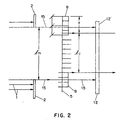
- Figs. 1 and 2 of the drawings shows a schematic representation of an assembly according to a first preferred embodiment of the present invention.
- a PLZT modulator is utilized.
- the collimated rays 1 of light incident on the modulator 5 are first blocked at both sides of the illumination zone by means of a mask 2.
- the remaining collimated rays pass the lens 3 and are thus directed to the surface of the modulator 5.
- Other suitable means to direct the remaining light to the surface of the modulator such as mirrors or the like will be apparent to those skilled in the art.
- the modulator 5 blocks selected ones of the light rays, as it will be explained in greater detail below.
- the beams of light 10 emerging from the modulator pass a lens 9 or other similar means as necessary and a polarizer 12 and finally reach an objective 11. On the other side of the objective, the image 14 can be obtained.
- the modulator 5 comprises a first group 6 of adjacent electrodes which are the imaging electrodes.
- additional electrodes 8 are located causing extraneous light rays 15 to be blocked downstream.
- the electrodes 6 and 8 are preferably arranged parallel to each other and, adjacent to these electrodes, a common electrode 7 is provided.
- the additional electrodes 8 are connected to a voltage source 26 in order to energize the electrodes with a voltage high enough to block the extraneous light rays 15.
- the group of imaging electrodes 6 is supplied with control voltages via a driver circuit 13.
- each of the imaging electrodes can be controlled or selected independently from the other imaging electrodes, thus allowing control of the modulator in accordance with the desired image.
- Fig. 2 schematically shows how the extraneous light rays 15 are blocked.
- the thin sheet-like bundle of rays 1 produced by a laser and associated optics is first limited by a mask 2 to a width l m but still covers more than the total width of the imaging electrodes.
- a mask 2 to a width l m but still covers more than the total width of the imaging electrodes.
- the useful imaging zone defined by the imaging electrodes 6 is illuminated but also a certain area on both sides of the imaging electrodes where the additional electrodes are provided. It illuminates an area extending beyond the width l u of imaging electrodes group 6 by overlapping rays covering section e on each side of the imaging electrodes.
- the thickness of the bundle of rays falls within the thickness of the modulator elements but its width extends beyond the width of their assembly represented by l u +2e.
- additional electrodes 8 On each side of the modulating imaging group of electrodes 6 are located additional electrodes 8 to cause extra marginal light rays 15 to be blocked downstream. Due to this structure, an area larger than the zone occupied by the imaging electrodes is illuminated resulting in a uniform illumination of the imaging electrodes of the modulator. The portion of the light phase front reaching the light-sensitive medium has a substantially uniform intensity whereas the edges of the light phase front illuminate the additional electrodes. This resulting extraneous radiation is however prevented from reaching the light-sensitive medium by the provision of the additional electrodes.
- the added electrodes 8 are connected to a common voltage control 26 ( Fig. 5 ).
- the field induced by this voltage interact with the inputted radiation to block its passage beyond the useful imaging zone. This is represented in Fig. 2 where it is shown that the rays 15, emerging from the electrodes 8 are blocked by polarizer 12 at location 12' independently of the operation of imaging electrodes 6.
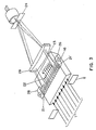
- Fig. 3 illustrates a second embodiment of the present invention utilizing a TIR modulator.
- modulators are well-known in the art, they operate to selectively deflect or bend high intensity beams from the laser. They depend on the effect of applying a voltage to an electrode pattern to induce change of the refractive index in an electro-optic element in the region of the surface of the element where the light is totally internally reflected. The emerging beams are diffracted into a series of orders. In general in images based on this system, rays of zero or low orders are prevented from reaching the light sensitive medium in the recording plane by a stop. The higher orders are focussed to form an image of the selected spots.
- the electrodes corresponding to these areas are activated, thus causing practically all the light energy emerging from the modulator to be concentrated in the higher order of the diffracted beams which are prevented from reaching the recording plane by a mask.
- the collimated light beams emerging from a laser and associated optics to form a sheet-like bundle are shown at 1. Their width limited by baffles 2, is large enough to fill the full width of the modulator 16.
- the electrodes of the modulator are divided into a first group of imaging electrodes individually subjected to voltage variations for the projection of individually selected light spots located in zone 22 ( Fig. 5 ), and a second group of electrodes located in zones 21 and 21' on each side of the first group, permanently energized through common circuit 26 in order to prevent extraneous "noise" rays extending beyond the imaging electrodes to reach the imaging plane.
- These rays shown at 23, after emerging from field lens 28, are blocked by mask 24 located at the focus of the field lens. This results in a uniform illumination of the imaging electrodes without allowing extraneous light rays to reach the light-sensitive medium.
- FIG. 4 illustrates in more detail how the extraneous light rays are blocked according to the present invention.
- a bundle of rays 32 is obtained by blocking the sheet-like bundle of light rays 30 by means of mechanical blocking means, such as a mask 2.
- the additional electrodes provided at the modulator 34 further reduce the illumination zone, so that only the light rays indicated by reference numeral 36 reach the imaging electrodes.
- the imaging and/or masking electrodes may be shaped and located as shown in Fig. 5 .
- Other acceptable configurations will be apparent to those skilled in the art.
- One arrangement of the electrodes are shown, e.g. in US-A-4 746 942 , incorporated herein by reference.
- the electrodes are joined into two conducting blocks each comprising a plurality of electrode fingers or arms (6,6', 8,8').
- the arms (6,8) of one block of electrodes are interleaved between adjacent arms (6',8') of the other block.
- the arms of the conducting blocks are divided into the imaging group 22 thus comprising two sets of adjacent electrodes, and the two sets of masking electrodes 21, 21' provided on both sides of the imaging group.
- the electrode arms 8 of the masking group are directly connected to a common voltage control 26, whereas control means, such as switches 27, are provided at the electrodes of the first set of electrodes of the imaging group.
- each electrode of the first set can be separately supplied with the control voltage.
Landscapes
- Engineering & Computer Science (AREA)
- Physics & Mathematics (AREA)
- Optics & Photonics (AREA)
- General Engineering & Computer Science (AREA)
- General Physics & Mathematics (AREA)
- Theoretical Computer Science (AREA)
- Multimedia (AREA)
- Signal Processing (AREA)
- Optical Modulation, Optical Deflection, Nonlinear Optics, Optical Demodulation, Optical Logic Elements (AREA)
Priority Applications (1)
| Application Number | Priority Date | Filing Date | Title |
|---|---|---|---|
| EP00916219A EP1078297B1 (en) | 1999-03-12 | 2000-03-10 | Imaging device and method for eliminating edge effects in spatial modulators |
Applications Claiming Priority (6)
| Application Number | Priority Date | Filing Date | Title |
|---|---|---|---|
| EP99104942 | 1999-03-12 | ||
| EP99104942 | 1999-03-12 | ||
| US290829 | 1999-04-13 | ||
| US09/290,829 US6222666B1 (en) | 1999-03-12 | 1999-04-13 | Electro-optic modulator and imaging device |
| PCT/US2000/006272 WO2000054096A1 (en) | 1999-03-12 | 2000-03-10 | Imaging device and method for eliminating edge effects in spatial modulators |
| EP00916219A EP1078297B1 (en) | 1999-03-12 | 2000-03-10 | Imaging device and method for eliminating edge effects in spatial modulators |
Publications (2)
| Publication Number | Publication Date |
|---|---|
| EP1078297A1 EP1078297A1 (en) | 2001-02-28 |
| EP1078297B1 true EP1078297B1 (en) | 2008-09-10 |
Family
ID=8237750
Family Applications (1)
| Application Number | Title | Priority Date | Filing Date |
|---|---|---|---|
| EP00916219A Expired - Lifetime EP1078297B1 (en) | 1999-03-12 | 2000-03-10 | Imaging device and method for eliminating edge effects in spatial modulators |
Country Status (8)
| Country | Link |
|---|---|
| US (1) | US6222666B1 (https=) |
| EP (1) | EP1078297B1 (https=) |
| JP (1) | JP4592960B2 (https=) |
| AU (1) | AU3735700A (https=) |
| CA (1) | CA2328870A1 (https=) |
| DE (1) | DE60040195D1 (https=) |
| IL (1) | IL139289A (https=) |
| WO (1) | WO2000054096A1 (https=) |
Families Citing this family (9)
| Publication number | Priority date | Publication date | Assignee | Title |
|---|---|---|---|---|
| US6369936B1 (en) * | 1999-03-12 | 2002-04-09 | Kodak Polychrome Graphics Llc | Pixel intensity control in electro-optic modulators |
| DE60122469T2 (de) | 2000-02-03 | 2007-05-03 | Kodak Polychrome Graphics Co. Ltd., Norwalk | Vorrichtung zum belichten eines wärmeempfindlichen mediums |
| EP1210649B1 (en) | 2000-03-31 | 2011-03-02 | Imax Corporation | Digital projection equipment and techniques |
| WO2001080555A1 (en) | 2000-04-18 | 2001-10-25 | Imax Corporation | Methods and systems for low loss separation and combination of light |
| CN1202662C (zh) | 2000-07-03 | 2005-05-18 | 图象公司 | 用于不可见接缝的复合投影显示设备和技术 |
| US6643049B2 (en) * | 2001-02-01 | 2003-11-04 | Kodak Polychrome Graphics Llc | Compact imaging head and high speed multi-head laser imaging assembly and method |
| US6798559B2 (en) * | 2002-09-06 | 2004-09-28 | Kodak Polychrome Graphics Llc | Electro-optic spatial modulator for high energy density |
| US7504072B2 (en) * | 2002-09-30 | 2009-03-17 | Agilent Technologies, Inc. | Biopolymeric array scanning devices that focus on the far side of an array and methods for using the same |
| US8251512B2 (en) | 2004-07-08 | 2012-08-28 | Imax Corporation | Equipment and methods for the display of high resolution images using multiple projection displays |
Family Cites Families (17)
| Publication number | Priority date | Publication date | Assignee | Title |
|---|---|---|---|---|
| US4316196A (en) | 1977-03-10 | 1982-02-16 | Bell & Howell Corporation | Illumination and light gate utilization methods and apparatus |
| US4804251A (en) | 1977-03-10 | 1989-02-14 | Imo Delaval Inc. | Electrode structures and electrooptic light gate systems |
| GB1600958A (en) * | 1977-03-10 | 1981-10-21 | Bell & Howell Co | Light gate utilization methods and apparatus |
| US4281904A (en) | 1979-06-21 | 1981-08-04 | Xerox Corporation | TIR Electro-optic modulator with individually addressed electrodes |
| US4554561A (en) | 1983-04-11 | 1985-11-19 | Xerox Corporation | Multi-channel electro-optic printer for printing plural image lines at once |
| JPS6026928A (ja) * | 1983-07-25 | 1985-02-09 | Matsushita Electric Ind Co Ltd | 光制御素子 |
| JPS6026927A (ja) | 1983-07-25 | 1985-02-09 | Matsushita Electric Ind Co Ltd | 光制御素子 |
| JPS60129726A (ja) * | 1983-12-16 | 1985-07-11 | Matsushita Electric Ind Co Ltd | 光制御素子 |
| US4639073A (en) | 1984-03-19 | 1987-01-27 | Xerox Corporation | Electro-optic pulse imaging raster output scanner |
| JPS61204613A (ja) * | 1985-03-07 | 1986-09-10 | Matsushita Electric Ind Co Ltd | 光シヤツタ−素子 |
| US4746942A (en) | 1985-11-23 | 1988-05-24 | Michel Moulin | Photocomposing machine and method |
| JPS6478863A (en) * | 1987-09-21 | 1989-03-24 | Minolta Camera Kk | Optical shutter array |
| JPS6438266A (en) * | 1987-08-03 | 1989-02-08 | Minolta Camera Kk | Optical recording head |
| US5054893A (en) | 1990-08-17 | 1991-10-08 | Schoonscan, Inc. | Electro-optic cell linear array |
| US5111320A (en) | 1990-11-29 | 1992-05-05 | Xerox Corporation | Ferrolectric liquid crystal devices having improved operating properties by using an electronic mask |
| JPH04344631A (ja) * | 1991-05-22 | 1992-12-01 | Brother Ind Ltd | シャトル形露光装置 |
| US5517359A (en) | 1995-01-23 | 1996-05-14 | Gelbart; Daniel | Apparatus for imaging light from a laser diode onto a multi-channel linear light valve |
-
1999
- 1999-04-13 US US09/290,829 patent/US6222666B1/en not_active Expired - Lifetime
-
2000
- 2000-03-10 EP EP00916219A patent/EP1078297B1/en not_active Expired - Lifetime
- 2000-03-10 DE DE60040195T patent/DE60040195D1/de not_active Expired - Lifetime
- 2000-03-10 IL IL13928900A patent/IL139289A/en not_active IP Right Cessation
- 2000-03-10 JP JP2000604262A patent/JP4592960B2/ja not_active Expired - Fee Related
- 2000-03-10 WO PCT/US2000/006272 patent/WO2000054096A1/en not_active Ceased
- 2000-03-10 CA CA002328870A patent/CA2328870A1/en not_active Abandoned
- 2000-03-10 AU AU37357/00A patent/AU3735700A/en not_active Abandoned
Also Published As
| Publication number | Publication date |
|---|---|
| AU3735700A (en) | 2000-09-28 |
| JP4592960B2 (ja) | 2010-12-08 |
| DE60040195D1 (de) | 2008-10-23 |
| IL139289A (en) | 2004-09-27 |
| IL139289A0 (en) | 2001-11-25 |
| US6222666B1 (en) | 2001-04-24 |
| WO2000054096A1 (en) | 2000-09-14 |
| CA2328870A1 (en) | 2000-09-14 |
| WO2000054096A9 (en) | 2001-12-27 |
| JP2003524196A (ja) | 2003-08-12 |
| EP1078297A1 (en) | 2001-02-28 |
Similar Documents
| Publication | Publication Date | Title |
|---|---|---|
| EP0333840B1 (en) | Multiplexed array exposing system having equi-angular scan exposure regions | |
| EP0334928B1 (en) | Scan-multiplexed light valve printer with band-reducing construction | |
| EP0198380B1 (en) | Light beam scanning apparatus and read-out or recording apparatus using the same | |
| CA1165026A (en) | High resolution optical-addressing device and electronic scanner and/or printer apparatus employing such device | |
| EP0077188B1 (en) | Electro-optic modulator | |
| EP1078297B1 (en) | Imaging device and method for eliminating edge effects in spatial modulators | |
| US4560994A (en) | Two dimensional electro-optic modulator for printing | |
| US5684620A (en) | High resolution imaging system and method of imaging using the same | |
| KR101004160B1 (ko) | 홀로그램 기록 장치 | |
| US4557563A (en) | Two dimensional electro-optic modulator for optical processing | |
| EP0335943B1 (en) | System for high resolution exposure address with coarser resolution exposing array | |
| US7009688B2 (en) | Printing by active tiling | |
| WO1982004369A1 (en) | Light valve apparatus | |
| WO1982002634A1 (en) | Electronic color imaging apparatus | |
| WO1991002283A1 (en) | Scanner | |
| US5982529A (en) | Apparatus for reducing linear artifacts in an optically-printed image | |
| US5969747A (en) | Efficient LED light geometry for optical printers | |
| EP0331722A1 (en) | Multicolor light valve imaging apparatus having electrode constructions for uniform transmission | |
| EP0807353A1 (en) | Picture display device | |
| JPH0522886B2 (https=) | ||
| JPH01144074A (ja) | 画像形成装置 | |
| JPS60126629A (ja) | 光変調光学素子 |
Legal Events
| Date | Code | Title | Description |
|---|---|---|---|
| PUAI | Public reference made under article 153(3) epc to a published international application that has entered the european phase |
Free format text: ORIGINAL CODE: 0009012 |
|
| AK | Designated contracting states |
Kind code of ref document: A1 Designated state(s): AT BE CH CY DE DK ES FI FR GB GR IE IT LI LU |
|
| AX | Request for extension of the european patent |
Free format text: AL;LT;LV;MK;RO;SI |
|
| 17P | Request for examination filed |
Effective date: 20010306 |
|
| RBV | Designated contracting states (corrected) |
Designated state(s): BE DE FR GB |
|
| RAP1 | Party data changed (applicant data changed or rights of an application transferred) |
Owner name: KODAK POLYCHROME GRAPHICS COMPANY LTD. |
|
| RAP1 | Party data changed (applicant data changed or rights of an application transferred) |
Owner name: KODAK PLYCHROME GRAPHICS GMBH |
|
| 17Q | First examination report despatched |
Effective date: 20060705 |
|
| RAP1 | Party data changed (applicant data changed or rights of an application transferred) |
Owner name: KODAK POLYCHROME GRAPHICS GMBH |
|
| RAP1 | Party data changed (applicant data changed or rights of an application transferred) |
Owner name: KODAK GRAPHIC COMMUNICATIONS GMBH |
|
| GRAP | Despatch of communication of intention to grant a patent |
Free format text: ORIGINAL CODE: EPIDOSNIGR1 |
|
| GRAS | Grant fee paid |
Free format text: ORIGINAL CODE: EPIDOSNIGR3 |
|
| GRAA | (expected) grant |
Free format text: ORIGINAL CODE: 0009210 |
|
| AK | Designated contracting states |
Kind code of ref document: B1 Designated state(s): BE DE FR GB |
|
| REG | Reference to a national code |
Ref country code: GB Ref legal event code: FG4D |
|
| REF | Corresponds to: |
Ref document number: 60040195 Country of ref document: DE Date of ref document: 20081023 Kind code of ref document: P |
|
| PG25 | Lapsed in a contracting state [announced via postgrant information from national office to epo] |
Ref country code: BE Free format text: LAPSE BECAUSE OF FAILURE TO SUBMIT A TRANSLATION OF THE DESCRIPTION OR TO PAY THE FEE WITHIN THE PRESCRIBED TIME-LIMIT Effective date: 20080910 |
|
| PLBE | No opposition filed within time limit |
Free format text: ORIGINAL CODE: 0009261 |
|
| STAA | Information on the status of an ep patent application or granted ep patent |
Free format text: STATUS: NO OPPOSITION FILED WITHIN TIME LIMIT |
|
| 26N | No opposition filed |
Effective date: 20090611 |
|
| PGFP | Annual fee paid to national office [announced via postgrant information from national office to epo] |
Ref country code: FR Payment date: 20130315 Year of fee payment: 14 Ref country code: GB Payment date: 20130225 Year of fee payment: 14 |
|
| PGFP | Annual fee paid to national office [announced via postgrant information from national office to epo] |
Ref country code: DE Payment date: 20140331 Year of fee payment: 15 |
|
| GBPC | Gb: european patent ceased through non-payment of renewal fee |
Effective date: 20140310 |
|
| REG | Reference to a national code |
Ref country code: FR Ref legal event code: ST Effective date: 20141128 |
|
| PG25 | Lapsed in a contracting state [announced via postgrant information from national office to epo] |
Ref country code: GB Free format text: LAPSE BECAUSE OF NON-PAYMENT OF DUE FEES Effective date: 20140310 Ref country code: FR Free format text: LAPSE BECAUSE OF NON-PAYMENT OF DUE FEES Effective date: 20140331 |
|
| REG | Reference to a national code |
Ref country code: DE Ref legal event code: R119 Ref document number: 60040195 Country of ref document: DE |
|
| PG25 | Lapsed in a contracting state [announced via postgrant information from national office to epo] |
Ref country code: DE Free format text: LAPSE BECAUSE OF NON-PAYMENT OF DUE FEES Effective date: 20151001 |