EP1078188B1 - Support of pipes and other elements from walls and ceilings - Google Patents
Support of pipes and other elements from walls and ceilings Download PDFInfo
- Publication number
- EP1078188B1 EP1078188B1 EP99920984A EP99920984A EP1078188B1 EP 1078188 B1 EP1078188 B1 EP 1078188B1 EP 99920984 A EP99920984 A EP 99920984A EP 99920984 A EP99920984 A EP 99920984A EP 1078188 B1 EP1078188 B1 EP 1078188B1
- Authority
- EP
- European Patent Office
- Prior art keywords
- channel
- rod
- threaded rod
- support device
- retain
- Prior art date
- Legal status (The legal status is an assumption and is not a legal conclusion. Google has not performed a legal analysis and makes no representation as to the accuracy of the status listed.)
- Expired - Lifetime
Links
- 238000000034 method Methods 0.000 claims description 5
- 238000009434 installation Methods 0.000 abstract description 7
- 238000004378 air conditioning Methods 0.000 abstract description 5
- 238000010438 heat treatment Methods 0.000 abstract description 4
- 238000009428 plumbing Methods 0.000 abstract description 2
- 239000002184 metal Substances 0.000 description 3
- 239000000725 suspension Substances 0.000 description 2
- 238000005452 bending Methods 0.000 description 1
- 230000005494 condensation Effects 0.000 description 1
- 238000009833 condensation Methods 0.000 description 1
- 230000008878 coupling Effects 0.000 description 1
- 238000010168 coupling process Methods 0.000 description 1
- 238000005859 coupling reaction Methods 0.000 description 1
- 238000004080 punching Methods 0.000 description 1
- XLYOFNOQVPJJNP-UHFFFAOYSA-N water Substances O XLYOFNOQVPJJNP-UHFFFAOYSA-N 0.000 description 1
Images


Classifications
-
- F—MECHANICAL ENGINEERING; LIGHTING; HEATING; WEAPONS; BLASTING
- F16—ENGINEERING ELEMENTS AND UNITS; GENERAL MEASURES FOR PRODUCING AND MAINTAINING EFFECTIVE FUNCTIONING OF MACHINES OR INSTALLATIONS; THERMAL INSULATION IN GENERAL
- F16L—PIPES; JOINTS OR FITTINGS FOR PIPES; SUPPORTS FOR PIPES, CABLES OR PROTECTIVE TUBING; MEANS FOR THERMAL INSULATION IN GENERAL
- F16L3/00—Supports for pipes, cables or protective tubing, e.g. hangers, holders, clamps, cleats, clips, brackets
- F16L3/08—Supports for pipes, cables or protective tubing, e.g. hangers, holders, clamps, cleats, clips, brackets substantially surrounding the pipe, cable or protective tubing
- F16L3/12—Supports for pipes, cables or protective tubing, e.g. hangers, holders, clamps, cleats, clips, brackets substantially surrounding the pipe, cable or protective tubing comprising a member substantially surrounding the pipe, cable or protective tubing
- F16L3/133—Supports for pipes, cables or protective tubing, e.g. hangers, holders, clamps, cleats, clips, brackets substantially surrounding the pipe, cable or protective tubing comprising a member substantially surrounding the pipe, cable or protective tubing and hanging from a pendant
Definitions
- the present invention relates to improvements in or relating to the support of pipes and other, typically, elongate elements from walls and ceilings, In particular, it relates to a hanger of particular use in suspending pipes and/or cables, especially in heating and air-conditioning installations and plumbing generally.
- Document EP-A-0 118 584 discloses such a pipe hanger.
- pipes are typically suspended from a ceiling or floor-joists by means of a threaded drop rod which engages at its upper end a corresponding threaded coupling secured to the ceiling or joist and its lower end, a munsing ring - a two-part ring which can be closed once the pipe has been inserted.
- This method requires very accurate cutting to length of the threaded rod to ensure that the pipes run horizontally or with the desired incline.
- the present invention provides a pipe support device having a generally U-shaped channel for receipt, in use, of a pipe and including adjustable engagement means to receive and retain a threaded rod; the engagement means including a channel provided in a face of the support device, the channel being of similar cross-sectional dimensions to the threaded rod and including a lateral toothed ridge having a plurality of teeth which, in use, engage the thread of the rod to retain the rod in position within the channel.
- the present invention provides a support system comprising a threaded socket including means for securing the socket to a surface; a complementarily threaded rod and a support of the type described above.
- the present invention provides a method of supporting a pipe from a threaded rod, the method including the steps of providing the object with a channel of similar cross-sectional dimensions as the threaded rod, which channel includes a lateral toothed ridge, having a plurality of teeth, which are selected to be of similar size and pitch to the thread of the rod.
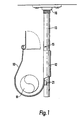
- support device in the form of a pipe hanger 10 supporting a pipe 11 in cross-section.
- the pipe hanger 10 which can be bent from sheet metal, has a generally U-shaped form when viewed side-on.
- the hanger 10 includes two generally L-shaped elongate lugs 12 extending from and along-the rear face thereof. In use, these lugs form a channel with the back-plate 15 of the hanger to receive and engage a threaded drop rod 13 which is secured to the ceiling or a joist in a conventional manner, as shown, by means of a threaded socket 16 screwed to the ceiling.
- each channel is adapted to engage a rod of different diameter, such as 8mm (13a) or 10mm (13b). Obviously, only one channel need be used at any one time.
- the edges of the lugs 12 curve inwardly to securely engage the rod 12.
- an aperture 20 is punched in the metal sheet of the hanger such that the metal thereby caused to protrude from the rear face of the hanger forms a lip 21 against which, in use, the threaded rod 13 is pressed, to retain the rod laterally in position.
- the hanger is provided with a lateral toothed ridge 25 associated with each channel and forming an additional short side wall to retain threaded rod 13.
- each toothed ridge is formed by punching or otherwise forming the appropriate shape in the back-plate of the hanger and then bending backwardly to the form shown in the figures.
- the dimensions of the teeth of the ridge are selected to correspond to the pitch of the groove of the threaded rod.
- the hanger 10 can be positioned at any height simply by clipping it onto the threaded rod 13 at the desired point. It no longer becomes necessary to cut the rod 13 to precisely the correct length.
- a clip at the top of the hanger 10 to prevent the pipe 11 from being lifted vertically out of the hanger.
- the clip comprises a tongue 30 pivotally mounted upon the front upright of the hanger.
- the tongue 30 includes a lug 31 which, in use, locates in a corresponding keyhole aperture 32 within the back plate 15.
- the aperture 32 is provided within a portion of the back plate 15 which extends, in the form or a further tongue, above the main body of the hanger and is divided therefrom by perforations 33 forming a line of weakness.
- the hangers of this invention can be set approximately, the pipework can then be installed and the lengths of the drop rods 13 adjusted, if necessary, to ensure the correct inclination.
- the hangers typically provide sufficient room for two pipes and also for electrical cables as required.
- hangers 10 can be used individually in much the same way as a conventional hook.
- the system will, accordingly, be suitable for a range of uses in the home, in shop-fitting and other industrial uses.
Landscapes
- Engineering & Computer Science (AREA)
- General Engineering & Computer Science (AREA)
- Mechanical Engineering (AREA)
- Supports For Pipes And Cables (AREA)
- Holders For Apparel And Elements Relating To Apparel (AREA)
- Walking Sticks, Umbrellas, And Fans (AREA)
Abstract
Description
Claims (4)
- A pipe support device (10) having a first generally U-shaped channel for receipt, in use, of a pipe (11) and including adjustable engagement means (12) to receive and retain a threaded rod (13); the engagement means including a second channel (12) provided in a face of the support device (10), this channel (12) being of similar cross-sectional dimensions to the threaded rod (13) and including a lateral toothed ridge (25) having a plurality of teeth which, in use, eogage the thread of the rod (13) to retain the rod (13) in position within the channel (12).
- A support device (10) as claimed in Claim 1 wherein the adjustable engagement means comprise two channels (12) in the face of the device, each channel (12) being adapted to receive a threaded rod (13) of different cross section.
- A support system comprising a threaded socket (16) including means for securing the socket to a surface; a complementarily threaded rod (13); and a support device as claimed in Claim 1 or Claim 2.
- A method of supporting a pipe (11) from a threaded rod (13), the method including the steps of using a pipe support device according to claim 1 or claim 2 choosing a channel (12) of similar cross-sectional dimensions as the threaded rod (13), which channel includes a lateral toothed ridge (25), having a plurality of teeth, which are selected to be of similar size and pitch to the thread of the rod (13).
Applications Claiming Priority (3)
| Application Number | Priority Date | Filing Date | Title |
|---|---|---|---|
| GB9809765 | 1998-05-07 | ||
| GBGB9809765.2A GB9809765D0 (en) | 1998-05-07 | 1998-05-07 | Pipe hanger |
| PCT/GB1999/001427 WO1999057472A1 (en) | 1998-05-07 | 1999-05-07 | Improvements in or relating to the support of pipes and other elements from walls and ceilings |
Publications (2)
| Publication Number | Publication Date |
|---|---|
| EP1078188A1 EP1078188A1 (en) | 2001-02-28 |
| EP1078188B1 true EP1078188B1 (en) | 2003-11-05 |
Family
ID=10831611
Family Applications (1)
| Application Number | Title | Priority Date | Filing Date |
|---|---|---|---|
| EP99920984A Expired - Lifetime EP1078188B1 (en) | 1998-05-07 | 1999-05-07 | Support of pipes and other elements from walls and ceilings |
Country Status (7)
| Country | Link |
|---|---|
| EP (1) | EP1078188B1 (en) |
| AT (1) | ATE253708T1 (en) |
| AU (1) | AU754502B2 (en) |
| CA (1) | CA2331830A1 (en) |
| DE (1) | DE69912596D1 (en) |
| GB (1) | GB9809765D0 (en) |
| WO (1) | WO1999057472A1 (en) |
Cited By (1)
| Publication number | Priority date | Publication date | Assignee | Title |
|---|---|---|---|---|
| US12438503B2 (en) | 2023-11-08 | 2025-10-07 | Panduit Corp. | Universal mount for wire hanger for solar applications |
Family Cites Families (2)
| Publication number | Priority date | Publication date | Assignee | Title |
|---|---|---|---|---|
| CA1191126A (en) * | 1983-03-07 | 1985-07-30 | Gerard Hurtubise | Pipe hanger |
| US4641989A (en) * | 1986-02-13 | 1987-02-10 | Joule' Inc. | Pipe hanger extension clip |
-
1998
- 1998-05-07 GB GBGB9809765.2A patent/GB9809765D0/en not_active Ceased
-
1999
- 1999-05-07 EP EP99920984A patent/EP1078188B1/en not_active Expired - Lifetime
- 1999-05-07 AT AT99920984T patent/ATE253708T1/en not_active IP Right Cessation
- 1999-05-07 DE DE69912596T patent/DE69912596D1/en not_active Expired - Lifetime
- 1999-05-07 AU AU38360/99A patent/AU754502B2/en not_active Ceased
- 1999-05-07 CA CA002331830A patent/CA2331830A1/en not_active Abandoned
- 1999-05-07 WO PCT/GB1999/001427 patent/WO1999057472A1/en not_active Ceased
Cited By (1)
| Publication number | Priority date | Publication date | Assignee | Title |
|---|---|---|---|---|
| US12438503B2 (en) | 2023-11-08 | 2025-10-07 | Panduit Corp. | Universal mount for wire hanger for solar applications |
Also Published As
| Publication number | Publication date |
|---|---|
| EP1078188A1 (en) | 2001-02-28 |
| CA2331830A1 (en) | 1999-11-11 |
| WO1999057472A1 (en) | 1999-11-11 |
| DE69912596D1 (en) | 2003-12-11 |
| ATE253708T1 (en) | 2003-11-15 |
| AU754502B2 (en) | 2002-11-21 |
| AU3836099A (en) | 1999-11-23 |
| GB9809765D0 (en) | 1998-07-08 |
Similar Documents
| Publication | Publication Date | Title |
|---|---|---|
| US6761341B2 (en) | Bar hanger and mounting clip assembly | |
| US6286265B1 (en) | Recessed lighting fixture mounting | |
| US5351920A (en) | Pipe support | |
| US6565048B1 (en) | Cable support bracket assembly | |
| US7455268B2 (en) | Hanger for fire sprinkler pipe | |
| EP1885566B1 (en) | Clip for suspending a pair of main tees in parallel relation | |
| US8616512B2 (en) | Multi-purpose cable support having bendable stem | |
| JP2002233024A (en) | Supporting means for long building service supply means | |
| US20040007378A1 (en) | Floor stand for mounting electrical box and for supporting conduit | |
| US5423507A (en) | Bracket for holding ceiling suspended fixtures | |
| US11261897B2 (en) | Structural fastener | |
| US5149040A (en) | Side beam pipe hanger and method of making | |
| US3132831A (en) | Clip-on pipe hanger | |
| AU754502B2 (en) | Improvements in or relating to the support of pipes and other elements from walls and ceilings | |
| HU225254B1 (en) | Holding device for holding long objects, especially roof drainage gutters, which are to be attached to a building | |
| US20020066836A1 (en) | Hanger for fire sprinkler pipe | |
| US4641989A (en) | Pipe hanger extension clip | |
| US20040245414A1 (en) | Perforated section supporting device adapted to be fixed to a surface such as a ceiling | |
| JP4002665B2 (en) | Vertical bolt support | |
| GB2135044A (en) | Louvre and mullion system | |
| JPH0635768U (en) | Pipe support member connector | |
| NZ543676A (en) | Guttering mounting bracket with clips arranged to correspond to desired fall of guttering | |
| JP3715951B2 (en) | Extension support device | |
| JPS6012009Y2 (en) | Hangers for suspended ceilings | |
| JP2013096649A (en) | Falling prevention fitting for air-conditioning equipment |
Legal Events
| Date | Code | Title | Description |
|---|---|---|---|
| PUAI | Public reference made under article 153(3) epc to a published international application that has entered the european phase |
Free format text: ORIGINAL CODE: 0009012 |
|
| 17P | Request for examination filed |
Effective date: 20001124 |
|
| AK | Designated contracting states |
Kind code of ref document: A1 Designated state(s): AT BE CH CY DE DK ES FI FR GB GR IE IT LI LU MC NL PT SE |
|
| 17Q | First examination report despatched |
Effective date: 20020704 |
|
| GRAH | Despatch of communication of intention to grant a patent |
Free format text: ORIGINAL CODE: EPIDOS IGRA |
|
| GRAS | Grant fee paid |
Free format text: ORIGINAL CODE: EPIDOSNIGR3 |
|
| GRAA | (expected) grant |
Free format text: ORIGINAL CODE: 0009210 |
|
| AK | Designated contracting states |
Kind code of ref document: B1 Designated state(s): AT BE CH CY DE DK ES FI FR GB GR IE IT LI LU MC NL PT SE |
|
| PG25 | Lapsed in a contracting state [announced via postgrant information from national office to epo] |
Ref country code: NL Free format text: LAPSE BECAUSE OF FAILURE TO SUBMIT A TRANSLATION OF THE DESCRIPTION OR TO PAY THE FEE WITHIN THE PRESCRIBED TIME-LIMIT Effective date: 20031105 Ref country code: LI Free format text: LAPSE BECAUSE OF FAILURE TO SUBMIT A TRANSLATION OF THE DESCRIPTION OR TO PAY THE FEE WITHIN THE PRESCRIBED TIME-LIMIT Effective date: 20031105 Ref country code: IT Free format text: LAPSE BECAUSE OF FAILURE TO SUBMIT A TRANSLATION OF THE DESCRIPTION OR TO PAY THE FEE WITHIN THE PRESCRIBED TIME-LIMIT;WARNING: LAPSES OF ITALIAN PATENTS WITH EFFECTIVE DATE BEFORE 2007 MAY HAVE OCCURRED AT ANY TIME BEFORE 2007. THE CORRECT EFFECTIVE DATE MAY BE DIFFERENT FROM THE ONE RECORDED. Effective date: 20031105 Ref country code: FR Free format text: LAPSE BECAUSE OF FAILURE TO SUBMIT A TRANSLATION OF THE DESCRIPTION OR TO PAY THE FEE WITHIN THE PRESCRIBED TIME-LIMIT Effective date: 20031105 Ref country code: FI Free format text: LAPSE BECAUSE OF FAILURE TO SUBMIT A TRANSLATION OF THE DESCRIPTION OR TO PAY THE FEE WITHIN THE PRESCRIBED TIME-LIMIT Effective date: 20031105 Ref country code: ES Free format text: LAPSE BECAUSE OF FAILURE TO SUBMIT A TRANSLATION OF THE DESCRIPTION OR TO PAY THE FEE WITHIN THE PRESCRIBED TIME-LIMIT Effective date: 20031105 Ref country code: CY Free format text: LAPSE BECAUSE OF FAILURE TO SUBMIT A TRANSLATION OF THE DESCRIPTION OR TO PAY THE FEE WITHIN THE PRESCRIBED TIME-LIMIT Effective date: 20031105 Ref country code: CH Free format text: LAPSE BECAUSE OF FAILURE TO SUBMIT A TRANSLATION OF THE DESCRIPTION OR TO PAY THE FEE WITHIN THE PRESCRIBED TIME-LIMIT Effective date: 20031105 Ref country code: BE Free format text: LAPSE BECAUSE OF FAILURE TO SUBMIT A TRANSLATION OF THE DESCRIPTION OR TO PAY THE FEE WITHIN THE PRESCRIBED TIME-LIMIT Effective date: 20031105 Ref country code: AT Free format text: LAPSE BECAUSE OF FAILURE TO SUBMIT A TRANSLATION OF THE DESCRIPTION OR TO PAY THE FEE WITHIN THE PRESCRIBED TIME-LIMIT Effective date: 20031105 |
|
| REG | Reference to a national code |
Ref country code: GB Ref legal event code: FG4D |
|
| REG | Reference to a national code |
Ref country code: CH Ref legal event code: EP |
|
| REF | Corresponds to: |
Ref document number: 69912596 Country of ref document: DE Date of ref document: 20031211 Kind code of ref document: P |
|
| REG | Reference to a national code |
Ref country code: IE Ref legal event code: FG4D |
|
| PG25 | Lapsed in a contracting state [announced via postgrant information from national office to epo] |
Ref country code: SE Free format text: LAPSE BECAUSE OF FAILURE TO SUBMIT A TRANSLATION OF THE DESCRIPTION OR TO PAY THE FEE WITHIN THE PRESCRIBED TIME-LIMIT Effective date: 20040205 Ref country code: GR Free format text: LAPSE BECAUSE OF FAILURE TO SUBMIT A TRANSLATION OF THE DESCRIPTION OR TO PAY THE FEE WITHIN THE PRESCRIBED TIME-LIMIT Effective date: 20040205 Ref country code: DK Free format text: LAPSE BECAUSE OF FAILURE TO SUBMIT A TRANSLATION OF THE DESCRIPTION OR TO PAY THE FEE WITHIN THE PRESCRIBED TIME-LIMIT Effective date: 20040205 |
|
| PG25 | Lapsed in a contracting state [announced via postgrant information from national office to epo] |
Ref country code: DE Free format text: LAPSE BECAUSE OF FAILURE TO SUBMIT A TRANSLATION OF THE DESCRIPTION OR TO PAY THE FEE WITHIN THE PRESCRIBED TIME-LIMIT Effective date: 20040206 |
|
| NLV1 | Nl: lapsed or annulled due to failure to fulfill the requirements of art. 29p and 29m of the patents act | ||
| PG25 | Lapsed in a contracting state [announced via postgrant information from national office to epo] |
Ref country code: LU Free format text: LAPSE BECAUSE OF NON-PAYMENT OF DUE FEES Effective date: 20040507 Ref country code: IE Free format text: LAPSE BECAUSE OF NON-PAYMENT OF DUE FEES Effective date: 20040507 |
|
| REG | Reference to a national code |
Ref country code: CH Ref legal event code: PL |
|
| PG25 | Lapsed in a contracting state [announced via postgrant information from national office to epo] |
Ref country code: MC Free format text: LAPSE BECAUSE OF NON-PAYMENT OF DUE FEES Effective date: 20040531 |
|
| PLBE | No opposition filed within time limit |
Free format text: ORIGINAL CODE: 0009261 |
|
| STAA | Information on the status of an ep patent application or granted ep patent |
Free format text: STATUS: NO OPPOSITION FILED WITHIN TIME LIMIT |
|
| 26N | No opposition filed |
Effective date: 20040806 |
|
| EN | Fr: translation not filed | ||
| REG | Reference to a national code |
Ref country code: IE Ref legal event code: MM4A |
|
| PG25 | Lapsed in a contracting state [announced via postgrant information from national office to epo] |
Ref country code: PT Free format text: LAPSE BECAUSE OF NON-PAYMENT OF DUE FEES Effective date: 20040405 |
|
| REG | Reference to a national code |
Ref country code: GB Ref legal event code: 732E Free format text: REGISTERED BETWEEN 20150813 AND 20150819 |
|
| PGFP | Annual fee paid to national office [announced via postgrant information from national office to epo] |
Ref country code: GB Payment date: 20180522 Year of fee payment: 20 |
|
| REG | Reference to a national code |
Ref country code: GB Ref legal event code: PE20 Expiry date: 20190506 |
|
| PG25 | Lapsed in a contracting state [announced via postgrant information from national office to epo] |
Ref country code: GB Free format text: LAPSE BECAUSE OF EXPIRATION OF PROTECTION Effective date: 20190506 |