EP1077867B1 - Power transmission assembly with a tetrahelical connecting rod, and method therefor. - Google Patents
Power transmission assembly with a tetrahelical connecting rod, and method therefor. Download PDFInfo
- Publication number
- EP1077867B1 EP1077867B1 EP98942015A EP98942015A EP1077867B1 EP 1077867 B1 EP1077867 B1 EP 1077867B1 EP 98942015 A EP98942015 A EP 98942015A EP 98942015 A EP98942015 A EP 98942015A EP 1077867 B1 EP1077867 B1 EP 1077867B1
- Authority
- EP
- European Patent Office
- Prior art keywords
- power transmission
- transmission assembly
- connecting rod
- tetrahedrons
- hub
- Prior art date
- Legal status (The legal status is an assumption and is not a legal conclusion. Google has not performed a legal analysis and makes no representation as to the accuracy of the status listed.)
- Expired - Lifetime
Links
- 230000005540 biological transmission Effects 0.000 title claims description 31
- 238000000034 method Methods 0.000 title claims description 15
- 238000002485 combustion reaction Methods 0.000 claims description 12
- 238000005461 lubrication Methods 0.000 claims description 5
- 229910000831 Steel Inorganic materials 0.000 claims description 3
- 239000004033 plastic Substances 0.000 claims description 3
- 239000010959 steel Substances 0.000 claims description 3
- 239000002131 composite material Substances 0.000 claims description 2
- 239000000835 fiber Substances 0.000 claims description 2
- 239000000446 fuel Substances 0.000 claims description 2
- 239000000203 mixture Substances 0.000 claims description 2
- 230000008901 benefit Effects 0.000 description 6
- 238000010276 construction Methods 0.000 description 5
- 230000007246 mechanism Effects 0.000 description 3
- 238000006073 displacement reaction Methods 0.000 description 2
- 239000000463 material Substances 0.000 description 2
- 230000008439 repair process Effects 0.000 description 2
- 230000008859 change Effects 0.000 description 1
- -1 e.g. Substances 0.000 description 1
- 229910001651 emery Inorganic materials 0.000 description 1
- 239000003733 fiber-reinforced composite Substances 0.000 description 1
- 238000004519 manufacturing process Methods 0.000 description 1
- QSHDDOUJBYECFT-UHFFFAOYSA-N mercury Chemical compound [Hg] QSHDDOUJBYECFT-UHFFFAOYSA-N 0.000 description 1
- 229910052753 mercury Inorganic materials 0.000 description 1
- 230000002035 prolonged effect Effects 0.000 description 1
- 239000003380 propellant Substances 0.000 description 1
- 230000003252 repetitive effect Effects 0.000 description 1
- 238000004904 shortening Methods 0.000 description 1
- 239000013585 weight reducing agent Substances 0.000 description 1
Images



Classifications
-
- F—MECHANICAL ENGINEERING; LIGHTING; HEATING; WEAPONS; BLASTING
- F16—ENGINEERING ELEMENTS AND UNITS; GENERAL MEASURES FOR PRODUCING AND MAINTAINING EFFECTIVE FUNCTIONING OF MACHINES OR INSTALLATIONS; THERMAL INSULATION IN GENERAL
- F16J—PISTONS; CYLINDERS; SEALINGS
- F16J7/00—Piston-rods
-
- B—PERFORMING OPERATIONS; TRANSPORTING
- B62—LAND VEHICLES FOR TRAVELLING OTHERWISE THAN ON RAILS
- B62M—RIDER PROPULSION OF WHEELED VEHICLES OR SLEDGES; POWERED PROPULSION OF SLEDGES OR SINGLE-TRACK CYCLES; TRANSMISSIONS SPECIALLY ADAPTED FOR SUCH VEHICLES
- B62M3/00—Construction of cranks operated by hand or foot
-
- Y—GENERAL TAGGING OF NEW TECHNOLOGICAL DEVELOPMENTS; GENERAL TAGGING OF CROSS-SECTIONAL TECHNOLOGIES SPANNING OVER SEVERAL SECTIONS OF THE IPC; TECHNICAL SUBJECTS COVERED BY FORMER USPC CROSS-REFERENCE ART COLLECTIONS [XRACs] AND DIGESTS
- Y10—TECHNICAL SUBJECTS COVERED BY FORMER USPC
- Y10T—TECHNICAL SUBJECTS COVERED BY FORMER US CLASSIFICATION
- Y10T74/00—Machine element or mechanism
- Y10T74/21—Elements
- Y10T74/2142—Pitmans and connecting rods
- Y10T74/2162—Engine type
Definitions
- This invention relates to a curved crank or rod to displace drive force from a pedal or cylinder head, for example, away from dead center, and to the corresponding power transmission method.
- crank/connecting rod designs are generally well known. Such designs are primarily used in human powered bicycles or non-human powered vehicles with internal or external combustion engines, be it fossil fueled, steam or other propellant, used on land, sea or air. The purpose of such a design is to transmit the force from the power source to the driving mechanism.
- US patent 4,974,554 to Emery (1990) taught to raise the piston head at top dead center to increase the mechanical and input/output efficiencies of an engine (internal or external combustion) by providing for an increased effective moment arm offered by the crankshaft rod journal during the period of peak combustion pressure.
- US patent 5,025,757 to Larsen provided for pivoting the engine block to change the top dead center distance.
- US patent 5,185,127 to Cuatico (1993) used an off-set connecting rod to obtain a better mechanical advantage in the internal combustion engine.
- US-A-3221464 discloses a generic tetrahedral configuration.
- a power transmission assembly comprising: a) a hub; b) a connecting rod, having a proximal end that is attached to the hub, for transmitting a driving force between the proximal end and a distal end characterised in that the connecting rod is tetrahelical.
- a power transmission method comprising: generating a drive force; and transmitting the drive force to a hub via a connecting rod characterised in that the connecting rod is tetrahelical.
- the embodiments of the invention described herein are concerned with a power transmission assembly for but not limited to bicycles or other crank and/or connecting rod devices.
- a novel method to transmit power, human or non-human, to a bicycle drive axle of a vehicle drive train is disclosed to increase the driving force, such that the driving force is directed away from the top dead center. This maximizes force because when the crank/connecting rod is at the highest point, it displaces this force away from the top dead center point.
- the advantage of this is that, by displacing the maximal force away from the top dead center point, the force applied to the crank will be at the maximal stroke height thus the driving force is used more efficiently.
- the present embodiments of the invention overcome the disadvantages of the prior art devices, which are suited for only one purpose, have complicated designs, have complicated constructions with multiple parts, and are expensive to construct.
- This invention is novel for it is adaptable to many applications, it is simple in design, it is simple in construction with no or few moving parts and it is inexpensive to construct.
- the hub is a crankshaft for an engine or axle for a bicycle.
- the connecting rod can be a piston rod or a bicycle crank arm, in two specific examples.
- the connecting rod is hollow, permitting lubrication and is constructed from steel, plastic, or reinforced fiber composites. Further, the rod is constructed from plural tetrahedrons that are attached to each other at triangular faces thereof. This forms a helical shape that moves the top dead-center point of the connecting rod relative to a straight arm.
- Fig. 1A shows a tetrahedron, frontal view.
- Fig. 1B shows a tetrahedron, side view.
- Fig. 1C shows a tetrahedron, top view.
- Fig. 2A shows two triple bonded tetrahedra, frontal view.
- Fig. 2B shows two triple bonded tetrahedra, side view.
- Fig. 2C shows two triple bonded tetrahedra, top view.
- Fig. 3A is a helical array of triple bonded tetrahedra forming a tetrahelix, frontal view.
- Fig. 3B is a helical array of triple bonded tetrahedra forming a tetrahelix, side view.
- Fig. 4 is a schematic lateral view of the tetrahelix crank illustrating several features of the present invention with an important feature thereof, namely the curved nature of the present invention, the simple design, displacement of the top dead center point.
- Fig. 5 is a schematic view from the front of the right handed tetrahelix crank.
- Fig. 6 is a schematic cross sectional top view of the right handed tetrahelix crank illustrating features of the present invention with an important feature thereof, namely the potential for a hollow central core that may permit easy lubrication and weight reduction without loss of strength.
- Fig. 7 is a schematic lateral view of the right and left tetrahelix cranks illustrating several features of the present invention with an important feature thereof, namely the curved nature of the present invention, the simple design, displacement of the top/bottom dead center points.
- Fig. 8 is a schematic view from the front of both right and left handed tetrahelix cranks.
- Fig. 9 is a schematic cross sectional top view of the right and left handed tetrahelix cranks.
- Fig. 10 is a schematic isometric view of the right and left handed tetrahelix cranks.
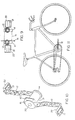
- Fig. 11 is a schematic view of the tetrahelix crank/connecting rod on a bicycle.
- Fig. 12 is a side, partial cut-away, view showing a tetrahelical connecting rod in an internal combustion engine.
- 10 is a tetrahelical bicycle crank arm assembly
- 12 is a hollow tetrahelical crank arm or connecting rod
- 14 is a cylindrical hub (27 mm outside diameter, standard mounting hole 30)
- 16 is a flange
- 21 is a pedal mounting lug (0.562" x 20 thread)
- 22 is a standard pedal assembly
- 30 is a standard mounting hole (disposed axially through its center to accept an end of a standard bottom bracket axle
- 31 is a standard bottom bracket axle
- 40 is a mounting hole (for bolting flange to larger chain sprocket (not shown)).
- 50 is a piston
- 51 is an exhaust valve
- 52 is a spark plug
- 53 is an intake valve
- 54 are rings on the piston 50
- 55 is the cylinder bore
- 56 is the crankshaft
- 57 is the engine block surrounding the piston bore and crankcase.
- FIG. 7 shows the tetrahelix or tetrahelical crank with a plurality of helical arrayed tetrahedra of the present invention.
- a typical embodiment of the tetrahelix crank assembly 10 shown includes a hollow centered crank arm 12 attached to a cylindrical hub 14.
- the hub is for mounting onto an axle crankshaft 31.
- the cylindrical hub 14 is attached to a flange 16 which will transmit the propelling forces to the drive wheel or chain sprocket mounting (not shown).
- the crank arm/connecting rod fabricated of any suitable material, e.g., steel, plastic or fiber-reinforced composites.
- the center of the crank/connecting rod is preferably hollow, maintaining strength while reducing weight and permitting lubrication if needed.
- the hub 14 is about 27 mm in outside diameter and has a standard mounting hole 30 disposed axially through its center to accept an end of a standard bottom bracket axle 31.
- the pedal mounting lug 21 has a 0.562" x 20 thread and a standard pedal assembly 22.
- the depicted tetrahelix crank arm 12 is for use on the right hand side 10 of the bicycle, it has a sprocket mounting flange 16 having a plurality of mounting holes 40.
- the preferred left hand tetrahelix crank arm assembly of the overall tetrahelical bicycle crank arm assembly 20 is similar to the' right hand tetrahelix crank assembly 12 except it has no sprocket mounting flange 16.
- the tetrahelix crank arm 12 has a length between opposing hole 30 and the pedal mounting lug 21 centers of 155-185 mm.
- Fig. 12 shows another application of the tetrahelical crank arm in a piston connecting rod, see reference 12.
- a piston 50 is contained within a cylinder bore 55.
- a fuel air mixture is received into the cylinder bore 55 through an intake valve 53. It is ignited by a spark plug 52. The combustion process creates a driving force which pushes the piston 50 downward in the illustration of Fig. 12.
- the curved, helical shape of the tetrahelical piston connecting rod 12 turns the crankshaft or hub 56, thereby turning the drive train of the vehicle, a car for example.
- the tetrahelix crank arm/connecting rod of this invention can be used to displace propelling force away from the top and bottom dead points easily and conveniently thus making the most efficient use of the propelling force.
- the tetrahelix crank arm/connecting rod has the additional advantages in that it is easy to construct; it is easy to manufacture; it permits maximum strength with minimum weight; it allows for a hollow center to reduce weight without loss of strength; it allows for a hollow center to provide lubrication when needed; it allows for any material to be used in its construction and still have maximum strength; it allows for use in human powered vehicles such as a bicycle as well as in machine driven vehicles either internal or external combustion that can be used on land, sea, air or space it allows for use in human powered machines such as a generator, pulley system as well as in machines that can be used on land, sea, air or space.
- the tetrahelix crank/connecting rod can be used not only for vehicles but in various sporting equipment or tools to provide the most efficient use of the propelling energy.
Landscapes
- Engineering & Computer Science (AREA)
- Mechanical Engineering (AREA)
- General Engineering & Computer Science (AREA)
- Chemical & Material Sciences (AREA)
- Combustion & Propulsion (AREA)
- Transportation (AREA)
- Shafts, Cranks, Connecting Bars, And Related Bearings (AREA)
- Transmission Devices (AREA)
- Pistons, Piston Rings, And Cylinders (AREA)
- Molds, Cores, And Manufacturing Methods Thereof (AREA)
Description
Claims (24)
- A power transmission assembly (10) comprising:a) a hub (14);b) a connecting rod (12), having a proximal end that is attached to the hub, for transmitting a driving force between the proximal end and a distal end characterised in that the connecting rod (12) is tetrahelical.
- The power transmission assembly (10) of Claim 1 wherein the hub (14) is a crankshaft.
- The power transmission assembly (10) of Claim 1 wherein the hub (14) is a crankshaft of an internal combustion engine.
- The power transmission assembly (10) of Claim 1 wherein the hub (14) is a crankshaft of a bicycle.
- The power transmission assembly (10) of Claim 1 wherein the power transmission assembly further comprises a piston (50) at the distal end for applying the driving force.
- The power transmission assembly (10) of Claim 1 wherein the power transmission assembly further comprises a pedal (22) at the distal end for transferring the driving force.
- The power transmission assembly (10) of Claim 1 wherein the connecting rod (12) is hollow.
- The power transmission assembly of Claim 7 wherein the hollow rod (12) permits lubrication.
- The power transmission assembly (10) of Claim 1 wherein the connecting rod (12) is constructed from one of steel, plastic, or reinforced fiber composite.
- A human or non-human powered vehicle comprising the power transmission assembly of claim 1.
- The power transmission assembly (10) of Claim 1 wherein the connecting rod (12) is constructed from plural tetrahedrons.
- The power transmission assembly (10) of Claim 11 wherein the tetrahedrons are bonded to each other.
- The power transmission assembly (10) of Claim 11 wherein the tetrahedrons are bonded to each other at triangular faces thereof.
- The power transmission assembly (10) of Claim 11 wherein the tetrahedrons are bonded together to form a helical shape.
- The power transmission assembly (10) of Claim 14, wherein the helical shape moves the top dead-center point of the connecting rod (12) relative to a straight arm.
- The power transmission assembly (10) of Claim 11 wherein the tetrahedrons are hollow.
- A bicycle comprising a power transmission assembly according to claim 1.
- A power transmission method, comprising:generating a drive force; andtransmitting the drive force to a hub (14) via a connecting rod (12) characterised in that the connecting rod (12) is tetrahelical.
- The power transmission method of Claim 18 wherein the step of generating the drive force comprises igniting a fuel mixture in a cylinder (55).
- The power transmission method of Claim 18 wherein the step of generating the drive force comprises exerting the drive force on a pedal (22) connected to the connecting rod (12).
- The power transmission method of Claim 18 wherein the connecting rod (12) is constructed from plural tetrahedrons.
- The power transmission method of Claim 21 wherein the tetrahedrons are bonded to each other.
- The power transmission method of Claim 21 wherein the bonded tetrahedrons form a helical shape.
- The power transmission method of Claim 21 wherein a top dead-center point of the connecting rod (12) is offset relative to a straight arm.
Applications Claiming Priority (3)
| Application Number | Priority Date | Filing Date | Title |
|---|---|---|---|
| US09/064,346 US6109135A (en) | 1995-12-27 | 1998-04-22 | Tetrahelical/curved bicycle crank arm/connecting rod for human/mechanical powered machines and the like |
| PCT/US1998/016487 WO1999054193A1 (en) | 1998-04-22 | 1998-08-07 | Tetrahelical/curved bicycle crank arm/connecting rod |
| US64346 | 2002-07-03 |
Publications (2)
| Publication Number | Publication Date |
|---|---|
| EP1077867A1 EP1077867A1 (en) | 2001-02-28 |
| EP1077867B1 true EP1077867B1 (en) | 2003-10-15 |
Family
ID=22055308
Family Applications (1)
| Application Number | Title | Priority Date | Filing Date |
|---|---|---|---|
| EP98942015A Expired - Lifetime EP1077867B1 (en) | 1998-04-22 | 1998-08-07 | Power transmission assembly with a tetrahelical connecting rod, and method therefor. |
Country Status (7)
| Country | Link |
|---|---|
| US (1) | US6109135A (en) |
| EP (1) | EP1077867B1 (en) |
| JP (1) | JP4252729B2 (en) |
| AU (1) | AU9015898A (en) |
| CA (1) | CA2330102C (en) |
| DE (1) | DE69819042T2 (en) |
| WO (1) | WO1999054193A1 (en) |
Families Citing this family (7)
| Publication number | Priority date | Publication date | Assignee | Title |
|---|---|---|---|---|
| DE102009010902A1 (en) | 2009-03-02 | 2010-09-16 | SOFHA GmbH Gesellschaft für Soft- und Hardware | Method and arrangement for configuring a printer driver and a corresponding computer program and a corresponding computer-readable storage medium |
| US8220434B2 (en) * | 2009-05-11 | 2012-07-17 | Tamerlan Mouradov | Internal-combustion engine |
| US10562588B2 (en) | 2015-09-01 | 2020-02-18 | The Hive Global, Inc | Bicycle cassette with locking connection |
| US11142280B2 (en) | 2016-03-24 | 2021-10-12 | The Hive Global, Inc. | Bicycle crank with spindle attachment structure |
| CN111542471A (en) | 2017-08-21 | 2020-08-14 | 劲锋铁马股份有限公司 | Bicycle cone pulley with clamping connection |
| US11932351B2 (en) | 2020-07-17 | 2024-03-19 | The Hive Global, Inc. | Conical bicycle cassette sprocket structure |
| US12030586B2 (en) | 2021-07-12 | 2024-07-09 | The Hive Global, Inc. | Seal for bicycle crank with differential chainring motion |
Family Cites Families (29)
| Publication number | Priority date | Publication date | Assignee | Title |
|---|---|---|---|---|
| US626630A (en) * | 1899-06-06 | Crank for bicycles | ||
| FR843684A (en) * | 1938-03-17 | 1939-07-07 | Mavic Ets | Bicycle bottom bracket crank |
| FR888628A (en) * | 1942-11-27 | 1943-12-17 | Bologne Forges | Bottom bracket crank set |
| US3221464A (en) * | 1961-03-17 | 1965-12-07 | Alvin E Miller | Tetrahelical structure |
| JPS602530B2 (en) * | 1979-08-29 | 1985-01-22 | 本田技研工業株式会社 | Conrod for internal combustion engine |
| WO1986005459A1 (en) * | 1985-03-13 | 1986-09-25 | Sté Look | Crank-gear for bicycle or similar locomotion vehicle |
| DE3663920D1 (en) * | 1985-03-29 | 1989-07-20 | Freder Stuckenbrok | Tread crank and tread crank driving gear for bicycles or similar, and a mount for such a tread crank driving gear |
| DE3715391A1 (en) * | 1987-05-08 | 1988-12-01 | Gerhard Mederer | INTERNAL COMBUSTION ENGINE OR OTHER DRIVE |
| US4890588A (en) * | 1988-01-29 | 1990-01-02 | Tillman John E | Means to control piston movement in relationship to crank arm rotation in an internal combustion engine |
| US4816009A (en) * | 1988-08-09 | 1989-03-28 | Gabriel Philipp | Power transmission system particularly useful for bicycles |
| US4966109A (en) * | 1989-04-05 | 1990-10-30 | Hitachi Construction Machinery Co., Ltd. | Hydraulic connecting rod |
| US4882945A (en) * | 1989-04-17 | 1989-11-28 | Jose Trevizo | Pedal extension device |
| US4974554A (en) * | 1989-08-17 | 1990-12-04 | Emery Lloyd H | Compound rod, sleeve and offset crankshaft assembly |
| US4960013A (en) * | 1989-12-04 | 1990-10-02 | Sander Keith D | Bicycle crank assembly |
| US5020287A (en) * | 1989-12-22 | 1991-06-04 | Woods Ray A | Structural building components incorporating integrated hyperbolic paraboloid elements |
| US5060536A (en) * | 1990-03-05 | 1991-10-29 | Boys Donald R | Flexible crank drive |
| US5010785A (en) * | 1990-06-11 | 1991-04-30 | Seattle Bike Supply | Crank arm for a bicylce |
| US5025757A (en) * | 1990-09-13 | 1991-06-25 | Larsen Gregory J | Reciprocating piston engine with a varying compression ratio |
| US5125288A (en) * | 1991-01-22 | 1992-06-30 | Amiet Alick G | Arcuate bicyle crank lever apparatus |
| US5186127A (en) * | 1991-01-28 | 1993-02-16 | Lorenzo Cuatico | Internal combustion engine with offset connecting journal |
| US5157988A (en) * | 1991-06-11 | 1992-10-27 | Pinkstock Donald H | Elastic crank for bicycles |
| US5136987A (en) * | 1991-06-24 | 1992-08-11 | Ford Motor Company | Variable displacement and compression ratio piston engine |
| US5179873A (en) * | 1991-09-09 | 1993-01-19 | Ocean State International, Inc. | Bicycle crank assembly |
| US5199324A (en) * | 1991-09-19 | 1993-04-06 | Saisan Partners | Adjustably variable pedal apparatus and method |
| US5178103A (en) * | 1991-12-23 | 1993-01-12 | Ford Motor Company | Variable compression ratio piston |
| US5207119A (en) * | 1992-02-06 | 1993-05-04 | Francois Garneau | Pedal mechanism for a human propulsion vehicle |
| US5201287A (en) * | 1992-08-03 | 1993-04-13 | Blish Nelson A | Variable stroke internal combustion engine |
| USD365049S (en) | 1994-06-28 | 1995-12-12 | Kuylman Stephan J | Crank arm set for bicycle |
| US5791202A (en) * | 1995-12-27 | 1998-08-11 | Karsdon; Jeffrey | Tetrahelical/curved bicycle crank-arm connecting rod for human/mechanical powered machines and the like |
-
1998
- 1998-04-22 US US09/064,346 patent/US6109135A/en not_active Expired - Lifetime
- 1998-08-07 AU AU90158/98A patent/AU9015898A/en not_active Abandoned
- 1998-08-07 EP EP98942015A patent/EP1077867B1/en not_active Expired - Lifetime
- 1998-08-07 WO PCT/US1998/016487 patent/WO1999054193A1/en not_active Ceased
- 1998-08-07 DE DE69819042T patent/DE69819042T2/en not_active Expired - Lifetime
- 1998-08-07 CA CA002330102A patent/CA2330102C/en not_active Expired - Fee Related
- 1998-08-07 JP JP2000544551A patent/JP4252729B2/en not_active Expired - Fee Related
Also Published As
| Publication number | Publication date |
|---|---|
| AU9015898A (en) | 1999-11-08 |
| US6109135A (en) | 2000-08-29 |
| DE69819042T2 (en) | 2004-07-22 |
| DE69819042D1 (en) | 2003-11-20 |
| JP4252729B2 (en) | 2009-04-08 |
| EP1077867A1 (en) | 2001-02-28 |
| JP2002512346A (en) | 2002-04-23 |
| WO1999054193A1 (en) | 1999-10-28 |
| CA2330102A1 (en) | 1999-10-28 |
| CA2330102C (en) | 2007-10-30 |
Similar Documents
| Publication | Publication Date | Title |
|---|---|---|
| US5682844A (en) | Twin crankshaft mechanism with arced connecting rods | |
| US5791202A (en) | Tetrahelical/curved bicycle crank-arm connecting rod for human/mechanical powered machines and the like | |
| CN202228184U (en) | Linear piston thrust internal combustion engine | |
| CA2330102C (en) | Tetrahelical/curved bicycle crank arm/connecting rod | |
| US20070079791A1 (en) | WaveTech engine | |
| EP0722532A1 (en) | Opposed piston engines | |
| CA2288473A1 (en) | Internal combustion cylinder engine | |
| WO2002036937A1 (en) | Dual torque barrel type engine | |
| EP1019615A1 (en) | Coupling arrangement for reciprocating piston engine | |
| US4712941A (en) | Tapered piston pin | |
| CN210049963U (en) | A reciprocating piston internal combustion engine without a crank connecting rod mechanism | |
| US4677722A (en) | Tapered piston pin | |
| RU99115776A (en) | INTERNAL COMBUSTION ENGINE | |
| EP1924784B1 (en) | A transmission arrangement | |
| KR200150269Y1 (en) | Fly wheel for a vehicle | |
| US6832592B2 (en) | Crankshaft coupling structure for use in an internal combustion engine | |
| RU2090768C1 (en) | Axial mechanism of internal combustion engines for converting reciprocating motion into rotation | |
| EP1462639A2 (en) | Spring-supported crankshaft coupling structure for use in an engine | |
| RU2021543C1 (en) | Internal combustion engine | |
| SU1380892A1 (en) | Arrangement for press-fitting bushings into the holes of base members | |
| WO2004009974A2 (en) | Internal combustion engine | |
| AU7192798A (en) | Internal combusion engines compression reciprocating engine | |
| RU2299341C2 (en) | Method of conversion of reciprocation of rod into rotation of shaft and electromechanical internal combustion engine | |
| WO1998004808A1 (en) | A mechanism for the conversion of reciprocating motion into rotary and vice versa | |
| RU93026079A (en) | INTERNAL COMBUSTION ENGINE |
Legal Events
| Date | Code | Title | Description |
|---|---|---|---|
| PUAI | Public reference made under article 153(3) epc to a published international application that has entered the european phase |
Free format text: ORIGINAL CODE: 0009012 |
|
| 17P | Request for examination filed |
Effective date: 20001113 |
|
| AK | Designated contracting states |
Kind code of ref document: A1 Designated state(s): BE DE DK ES FR GB IE IT NL SE |
|
| 17Q | First examination report despatched |
Effective date: 20020307 |
|
| GRAH | Despatch of communication of intention to grant a patent |
Free format text: ORIGINAL CODE: EPIDOS IGRA |
|
| RTI1 | Title (correction) |
Free format text: POWER TRANSMISSION ASSEMBLY WITH A TETRAHELICAL CONNECTING ROD, AND METHOD THEREFOR. |
|
| GRAH | Despatch of communication of intention to grant a patent |
Free format text: ORIGINAL CODE: EPIDOS IGRA |
|
| GRAA | (expected) grant |
Free format text: ORIGINAL CODE: 0009210 |
|
| AK | Designated contracting states |
Kind code of ref document: B1 Designated state(s): BE DE DK ES FR GB IE IT NL SE |
|
| PG25 | Lapsed in a contracting state [announced via postgrant information from national office to epo] |
Ref country code: BE Free format text: LAPSE BECAUSE OF FAILURE TO SUBMIT A TRANSLATION OF THE DESCRIPTION OR TO PAY THE FEE WITHIN THE PRESCRIBED TIME-LIMIT Effective date: 20031015 |
|
| REG | Reference to a national code |
Ref country code: GB Ref legal event code: FG4D |
|
| REG | Reference to a national code |
Ref country code: IE Ref legal event code: FG4D |
|
| REF | Corresponds to: |
Ref document number: 69819042 Country of ref document: DE Date of ref document: 20031120 Kind code of ref document: P |
|
| PG25 | Lapsed in a contracting state [announced via postgrant information from national office to epo] |
Ref country code: DK Free format text: LAPSE BECAUSE OF FAILURE TO SUBMIT A TRANSLATION OF THE DESCRIPTION OR TO PAY THE FEE WITHIN THE PRESCRIBED TIME-LIMIT Effective date: 20040115 |
|
| REG | Reference to a national code |
Ref country code: SE Ref legal event code: TRGR |
|
| PG25 | Lapsed in a contracting state [announced via postgrant information from national office to epo] |
Ref country code: ES Free format text: LAPSE BECAUSE OF FAILURE TO SUBMIT A TRANSLATION OF THE DESCRIPTION OR TO PAY THE FEE WITHIN THE PRESCRIBED TIME-LIMIT Effective date: 20040126 |
|
| ET | Fr: translation filed | ||
| PG25 | Lapsed in a contracting state [announced via postgrant information from national office to epo] |
Ref country code: IE Free format text: LAPSE BECAUSE OF NON-PAYMENT OF DUE FEES Effective date: 20040809 |
|
| PLBE | No opposition filed within time limit |
Free format text: ORIGINAL CODE: 0009261 |
|
| STAA | Information on the status of an ep patent application or granted ep patent |
Free format text: STATUS: NO OPPOSITION FILED WITHIN TIME LIMIT |
|
| 26N | No opposition filed |
Effective date: 20040716 |
|
| REG | Reference to a national code |
Ref country code: IE Ref legal event code: MM4A |
|
| PGFP | Annual fee paid to national office [announced via postgrant information from national office to epo] |
Ref country code: SE Payment date: 20090827 Year of fee payment: 12 |
|
| EUG | Se: european patent has lapsed | ||
| PG25 | Lapsed in a contracting state [announced via postgrant information from national office to epo] |
Ref country code: SE Free format text: LAPSE BECAUSE OF NON-PAYMENT OF DUE FEES Effective date: 20100808 |
|
| PGFP | Annual fee paid to national office [announced via postgrant information from national office to epo] |
Ref country code: FR Payment date: 20130819 Year of fee payment: 16 Ref country code: GB Payment date: 20130827 Year of fee payment: 16 |
|
| PGFP | Annual fee paid to national office [announced via postgrant information from national office to epo] |
Ref country code: IT Payment date: 20130823 Year of fee payment: 16 |
|
| PGFP | Annual fee paid to national office [announced via postgrant information from national office to epo] |
Ref country code: NL Payment date: 20140826 Year of fee payment: 17 |
|
| PGFP | Annual fee paid to national office [announced via postgrant information from national office to epo] |
Ref country code: DE Payment date: 20140929 Year of fee payment: 17 |
|
| GBPC | Gb: european patent ceased through non-payment of renewal fee |
Effective date: 20140807 |
|
| PG25 | Lapsed in a contracting state [announced via postgrant information from national office to epo] |
Ref country code: IT Free format text: LAPSE BECAUSE OF NON-PAYMENT OF DUE FEES Effective date: 20140807 |
|
| REG | Reference to a national code |
Ref country code: FR Ref legal event code: ST Effective date: 20150430 |
|
| PG25 | Lapsed in a contracting state [announced via postgrant information from national office to epo] |
Ref country code: GB Free format text: LAPSE BECAUSE OF NON-PAYMENT OF DUE FEES Effective date: 20140807 |
|
| PG25 | Lapsed in a contracting state [announced via postgrant information from national office to epo] |
Ref country code: FR Free format text: LAPSE BECAUSE OF NON-PAYMENT OF DUE FEES Effective date: 20140901 |
|
| REG | Reference to a national code |
Ref country code: DE Ref legal event code: R119 Ref document number: 69819042 Country of ref document: DE |
|
| REG | Reference to a national code |
Ref country code: NL Ref legal event code: MM Effective date: 20150901 |
|
| PG25 | Lapsed in a contracting state [announced via postgrant information from national office to epo] |
Ref country code: NL Free format text: LAPSE BECAUSE OF NON-PAYMENT OF DUE FEES Effective date: 20150901 |
|
| PG25 | Lapsed in a contracting state [announced via postgrant information from national office to epo] |
Ref country code: DE Free format text: LAPSE BECAUSE OF NON-PAYMENT OF DUE FEES Effective date: 20160301 |