EP1077850B1 - Vehicle stabilizing device and method for modifying brake pressures - Google Patents
Vehicle stabilizing device and method for modifying brake pressures Download PDFInfo
- Publication number
- EP1077850B1 EP1077850B1 EP99924936A EP99924936A EP1077850B1 EP 1077850 B1 EP1077850 B1 EP 1077850B1 EP 99924936 A EP99924936 A EP 99924936A EP 99924936 A EP99924936 A EP 99924936A EP 1077850 B1 EP1077850 B1 EP 1077850B1
- Authority
- EP
- European Patent Office
- Prior art keywords
- pressure
- slip
- auf
- vehicle
- wheel
- Prior art date
- Legal status (The legal status is an assumption and is not a legal conclusion. Google has not performed a legal analysis and makes no representation as to the accuracy of the status listed.)
- Expired - Lifetime
Links
- 230000000087 stabilizing effect Effects 0.000 title claims description 25
- 238000000034 method Methods 0.000 title claims description 20
- 230000009467 reduction Effects 0.000 claims description 81
- 230000000694 effects Effects 0.000 claims description 11
- 230000015556 catabolic process Effects 0.000 description 5
- 238000006731 degradation reaction Methods 0.000 description 4
- 230000006641 stabilisation Effects 0.000 description 4
- 238000011105 stabilization Methods 0.000 description 4
- 230000006872 improvement Effects 0.000 description 3
- 230000001133 acceleration Effects 0.000 description 2
- 230000004913 activation Effects 0.000 description 1
- 230000008901 benefit Effects 0.000 description 1
- 230000000903 blocking effect Effects 0.000 description 1
- 230000008859 change Effects 0.000 description 1
- 238000006243 chemical reaction Methods 0.000 description 1
- 230000003247 decreasing effect Effects 0.000 description 1
- 238000010586 diagram Methods 0.000 description 1
- 230000000977 initiatory effect Effects 0.000 description 1
- 238000002955 isolation Methods 0.000 description 1
- 230000008569 process Effects 0.000 description 1
- 230000004044 response Effects 0.000 description 1
- 239000007787 solid Substances 0.000 description 1
Images


Classifications
-
- B—PERFORMING OPERATIONS; TRANSPORTING
- B60—VEHICLES IN GENERAL
- B60T—VEHICLE BRAKE CONTROL SYSTEMS OR PARTS THEREOF; BRAKE CONTROL SYSTEMS OR PARTS THEREOF, IN GENERAL; ARRANGEMENT OF BRAKING ELEMENTS ON VEHICLES IN GENERAL; PORTABLE DEVICES FOR PREVENTING UNWANTED MOVEMENT OF VEHICLES; VEHICLE MODIFICATIONS TO FACILITATE COOLING OF BRAKES
- B60T8/00—Arrangements for adjusting wheel-braking force to meet varying vehicular or ground-surface conditions, e.g. limiting or varying distribution of braking force
- B60T8/17—Using electrical or electronic regulation means to control braking
- B60T8/1755—Brake regulation specially adapted to control the stability of the vehicle, e.g. taking into account yaw rate or transverse acceleration in a curve
-
- B—PERFORMING OPERATIONS; TRANSPORTING
- B60—VEHICLES IN GENERAL
- B60T—VEHICLE BRAKE CONTROL SYSTEMS OR PARTS THEREOF; BRAKE CONTROL SYSTEMS OR PARTS THEREOF, IN GENERAL; ARRANGEMENT OF BRAKING ELEMENTS ON VEHICLES IN GENERAL; PORTABLE DEVICES FOR PREVENTING UNWANTED MOVEMENT OF VEHICLES; VEHICLE MODIFICATIONS TO FACILITATE COOLING OF BRAKES
- B60T2270/00—Further aspects of brake control systems not otherwise provided for
- B60T2270/30—ESP control system
- B60T2270/304—ESP control system during driver brake actuation
Definitions
- the invention relates to a vehicle stabilizing device and a method according to the preamble of claims 1 and 13, respectively.
- the basic ESP Electronic Stability Program
- the strategy for stabilizing a vehicle is in unbraked case in the targeted braking of individual wheels through active pressure build-up in the corresponding wheel brake cylinder. This is through lateral force reduction and simultaneous longitudinal or Brake force build-up a stabilizing torque (Yaw moment) stamped into the vehicle structure.
- Yaw moment a stabilizing torque stamped into the vehicle structure.
- In contrast to the unbraked case with simultaneous driver braking Initiation of a stabilizing yaw moment from one existing form and thus also power distribution to the Wheels are assumed that are due to the driver form or if necessary by the one controlled by the ABS (anti-lock braking system) Pressure level in the wheel brake cylinders.
- 40 456 A1 is a vehicle stabilizing Method and from EP-A-0 771 707 a Vehicle stabilizing device known. That in DE 38 The method described in 40 456 A1 modifies the brake pressures the wheels according to the actual and target brake slip and the Slip angles while the E P-A-0 771 707 die Pedal actuation speed to detect panic Uses braking response as a parameter.
- the invention has for its object a braking strategy to indicate with which a vehicle with actively braked Pressure build-up can be stabilized so that there is an optimum from the driver's braking request, the vehicle stabilization or steering ability of the vehicle and the pedal and Adjusts noise comfort ..
- a vehicle stabilizing device for Modifying brake pressures on wheels in a vehicle after Input data that a change in Brake pressures on at least one wheel after one of the Driver brake pressure determined influencing one of several Influencing cycles or influencing strategies for Providing interventional unit will be as long as possible with the help of the existing driver form without active pressure build-up stabilizing above this pressure level of the vehicle with the best possible braking.
- the pressure build-up requirement is in the second Influencing cycle equal to the driver form, so that in addition the isolating and switching valve also the inlet valve of the Corresponding wheel remains open throughout, resulting in a further improvement in pedal comfort arises.
- the invention also relates to a vehicle stabilizing Method for modifying brake pressures on wheels a vehicle according to input data in which the brake pressures on at least one wheel after one of the driver brake pressure certain influence, which consists of several Influencing cycles or influencing strategies is selected, changed.
- the effectiveness of the procedure and the comfort sustainable compared to the previous one Intervention improved.
- the pressure reduction on the outside front wheel in the event of understeer Cornering forces built up the steering ability of the Improve vehicle and its stabilization significantly. Due to the simultaneous pressure build-up on the inside of the curve The rear wheel is reduced by the braking Limited pressure build-up on the front wheel. Avoiding the Pressure build-up beyond the driver form and thus the Bypassing the energization of the isolating and switching valve, especially for small to medium-sized ones Vehicle instabilities, increases comfort during the Intervention.
- the improvement in comfort during ESP interventions is included medium and small vehicle instability by avoidance of a pressure build-up via the driver pre-print clearly in Foreground.
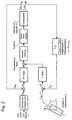
- the basic elements of the ESP control loop can be seen in FIG. 2.
- the total controller output variable M G of the PD controller (yaw rate ⁇ ) and P controller (slip angle speed ⁇ ) is determined in the following way:
- the index Fhz identifies the actual values of the yaw rate ⁇ ⁇ , yaw acceleration and the vehicle's slip angle velocity ⁇ ⁇ .
- the corresponding target values are designated with the index target.
- the control deviations of the yaw rate and yaw acceleration resulting from the difference between the actual and target values are ⁇ ⁇ and ⁇ ,
- the exit rule thresholds can be recognized by the index out.
- the gain factors of the PD controller ( and ) depend on the coefficient of friction of the tire / road pairing (linear approach) and the gain factor of the P controller ( ) the degree of stationary motion of the vehicle.
- the controller output variable M G grows proportionally to the vehicle instability and thus also to the required yaw moment, which is necessary for the desired vehicle stabilization.
- This yaw moment is impressed into the vehicle structure by one-sided pressure build-up in the actuators (wheel brakes).
- the imprinted braking torques on the wheels result in a build-up of braking force in the vehicle's longitudinal direction and a lateral force reduction in the transverse direction, which generate the desired yaw moment when the meshing wheels are selected appropriately.
- this setting of the meshing wheels must first be made. If the vehicle is understeering, the rear wheel on the inside of the curve is selected for the build-up of pressure and the front wheel on the outside of the curve if the driving behavior is oversteering.
- K Br A K, v A K, h r w, v r w, h C * v C * H
- This level is determined by a slip regulator. Taking into account the actual slip measured on the wheel, the latter continuously calculates a set pressure P slip in the wheel cylinder in the background, which would lead to a set slip of 50% (FIG. 1). If this pressure p slip is less than the pressure request p up determined from Eq. (5), then P slip becomes the new pressure request P up . Due to the control quality of the slip controller, a slip band of approximately 30-70% is preferably set in this operating range.
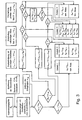
- the first element of the device or method according to the invention consists in the suitable selection of the engagement wheels for the pressure build-up and pressure reduction for a given control tendency of the vehicle (FIG. 3 shows the elements of the influencing cycles or the influencing strategy in the form of a flow chart).
- the pressure build-up takes place as in the ESP intervention without pressure reduction in the case of oversteer on the outside front wheel and in the understeer case on the inside rear wheel.
- the diagonally located wheel is used for pressure reduction, ie the front wheel on the outside of the curve in the event of understeer and the rear wheel on the inside of the curve in the event of oversteer.
- the reference pressures p up, ref and p down, ref essentially record the above-mentioned level.
- p is on
- ref is equal to the reference pressure from equation (5).
- the reference pressure p ab, ref is equal to the actual pressure of the reduction wheel when control begins (this value is also stored), here pressure changes of the opposite wheel of the same axis are taken into account within the control.
- ⁇ p on from M G, on is determined according to Eq. (2) or (3).
- ⁇ p ab applies accordingly for the front axle (understeer case)
- Ap off v M Gave .
- ⁇ p from, h K br M Gave
- K ' K br
- K ' 1 / K br
- the pressure requirement p ab according to Eq. (7) resulting with the pressure reduction component according to Eq.
- the inlet valve of the corresponding wheel can also remain open, which results in a further improvement in pedal comfort.
- the second influencing cycle or the second stage can also be achieved if the solid pressure of the slip regulator P slip is less than the driver pre-pressure p main . Then p is limited to p slip before p main is reached. The breakdown share for the diagonally lying wheel is then analogous to the relationship calculated. In this case, however, the inlet valve does not remain de-energized.
- the calculated degradation requirement P ab according to Eqs. (7) and (11) is lower than the lower limit pressure P lim , so that it is limited to the value of P lim .
- the controller output variable M G is therefore not yet fully implemented due to the pressure increase on the wheel in the pressure build-up to P main and the pressure reduction on the wheel in the pressure reduction. In this situation, the comfort must be reset in favor of adequate vehicle stabilization, ie the remaining portion of the regulator output variable M G that cannot be deducted by the pressure reduction must be used for the active pressure increase via the driver pre-pressure p main . This energizes both the isolating and the switching valves of the circuit in the pressure build-up.
- the determination of the pressure requirement of the wheel in the pressure build-up P on can be based on the relationship with K 'according to Eq. (12) or (13).
- the request P up, m is calculated from Eq. (14) or (15) and P ab, m from Eq. (7) and (11). If, in the third stage, the pressure build-up has already been limited to p slip by the slip controller before reaching the driver pre-pressure p main , a further pressure increase is no longer possible, ie the effectiveness of the overall intervention has already reached its limit. In this case, the energization of the isolating and changeover valve is again omitted.
- the fourth influencing cycle or the fourth stage is reached when partial pressure reduction is not even possible, i.e. before the control begins, the admission pressure is lower than the lower limit pressure p lim .
- the reference pressure p ab, ref is used as a comparison value for the form.
- the pressure requirement on the wheel in the pressure build-up is increased via the driver pre-pressure P main according to Eq. (14) or (15), so that the pressure modulation does not differ from the original case without pressure reduction.
- the slip regulator can also limit the pressure build-up to p slip .
- the influencing cycle is one, ie state 1. If not, the first step is to calculate the pressure reduction requirement with maximum pressure reduction (see Eq. (7) and (11)). If the subsequent decision as to whether the degradation can take place completely (condition A: p ab, m > P lim ) is positive, then the influencing cycle is two, ie state 2, and the final pressure requirements p up and p down can be determined. If condition A is not fulfilled, the next step is to decide whether at least a partial pressure reduction is possible.
- condition B p ab, ref > p lim
- condition B partial pressure reduction is possible
- the influencing cycle three i.e. state 3
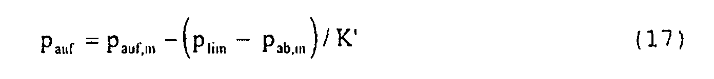
- the pressure requirements can be calculated (pressure build-up requirement see Eq. (17)).
- condition B is not fulfilled, then no degradation is possible and the influencing cycle four, ie state 4, is present.
- condition A in this branch is fulfilled and the influencing cycle two, ie state 2, is present, then the pressure build-up request is set to p main , ie the slip controller is then no longer active. If the calculated pressure can not be completely discontinued and is positive condition B, confirm the final, reduced by the reduction percentage pressure increase requirement p is to be calculated and then checked whether the slip control is still active. If not, then p is three on the final pressure build-up request in the influencing cycle or state 3, otherwise this is equal to p slip .
- An important element of the pressure reduction in the second or third influencing cycle or in states 2 and 3 is that the calculated pressure reduction is not carried out within one time step of the controller, but following a linear course over a certain number n of time steps (order of magnitude: 5) is divided. As a result, the resulting yaw moment can be built up more moderately and better metered. The status remains during this time, ie a new recognition is not carried out. The pressure reduction state is ended and a new recognition of the state is permitted as soon as the specified period of time has passed or the meshing wheels, ie the control tendency of the vehicle, changes.
- the reference pressure P ab, ref is also newly determined loopoa textbook even when the influencing cycle or state 2 or 3 is active. This does not apply to the maximum pressure reduction request P ab, m and the maximum pressure reduction ⁇ P ab, m , ie the values from the last loop are adopted.
- the pressure reduction requirement p ab, i according to equations (18 and (19)) is limited downwards to the pressure p lim .
- the pressure build-up request P up, m and the setpoint pressure of the slip regulator P slip are also adapted to the current input variables in each time step during the active pressure reduction phase. This happens because, on the one hand, the slip control must be active in the background in order to prevent blocking on the meshing wheel. Furthermore, especially in the influencing cycle or state 3 (complete dismantling not possible and build-up via the driver pre-pressure), an increase in the pressure build-up requirement must be possible with increasing vehicle instability.
- the information about the state, the maximum pressure reduction request P ab, m and the maximum pressure reduction ⁇ P ab, m is taken from the last time step of the active pressure reduction.
- a decision is made as to whether the pressure reduction is still active or whether the state must be redetermined (this is done again according to FIG. 3). If the influencing cycle or state 2 or 3 is still active, then the pressure reduction request is made according to counter i according to Eq. (18) or (19) calculated.
- the exact definition of the pressure build-up requirement is preceded by a determination of the pressure range, which corresponds to the logical structure of that described in FIG. 2.
- the pressure build-up request may drop below the driver pre-pressure due to a greatly decreasing instability of the vehicle when the slip regulator is not active.
- the pressure build-up request P on, m is accepted both in the influencing cycle or state 2 and in the influencing cycle or state 3, ie it can also drop below the driver pre-pressure P main .
Description
Die Erfindung betrifft eine fahrzeugstabilisierende Einrichtung
und ein Verfahren nach dem Oberbegriff des Anspruchs 1 bzw. 13.The invention relates to a vehicle stabilizing device
and a method according to the preamble of
Die prinzipielle ESP (Elektronisches Stabilitäts Programm) - Strategie zur Stabilisierung eines Fahrzeugs besteht im ungebremsten Fall in der gezielten Abbremsung einzelner Räder durch aktiven Druckaufbau im entsprechenden Radbremszylinder. Hierdurch wird durch Seitenkraftabbau und gleichzeitigen Längsoder Bremskraftaufbau ein stabilisierendes Drehmoment (Giermoment) in die Fahrzeugstruktur eingeprägt. Im Gegensatz zum ungebremsten Fall muß bei gleichzeitiger Fahrerbremsung zur Einleitung eines stabilisierenden Giermoments von einer vorhandenen Vordruck- und damit auch Kraftverteilung an den Rädern ausgegangen werden, die sich durch den Fahrervordruck oder ggf. durch das vom ABS (Antiblockier-System) eingesteuerte Druckniveau in den Radbremszylindern einstellt.The basic ESP (Electronic Stability Program) - The strategy for stabilizing a vehicle is in unbraked case in the targeted braking of individual wheels through active pressure build-up in the corresponding wheel brake cylinder. This is through lateral force reduction and simultaneous longitudinal or Brake force build-up a stabilizing torque (Yaw moment) stamped into the vehicle structure. In contrast to the unbraked case with simultaneous driver braking Initiation of a stabilizing yaw moment from one existing form and thus also power distribution to the Wheels are assumed that are due to the driver form or if necessary by the one controlled by the ABS (anti-lock braking system) Pressure level in the wheel brake cylinders.
Aus der DE 38 40 456 A1 ist eine fahrzeugstabilisierendes Verfahren und aus der EP-A-0 771 707 eine fahrzeugstabilisierende Einrichtung bekannt. Das in der DE 38 40 456 A1 beschriebene Verfahren modfiziert die Bremsdrücke an den Rädern nach dem Ist und Soll Bremschlupf und den Schräglaufwinkeln während die E P-A-0 771 707 die Pedalbetätigungsgeschwindigkeit zur Erkennung einer panischen Bremsreaktion als Parameter heranzieht. From DE 38 40 456 A1 is a vehicle stabilizing Method and from EP-A-0 771 707 a Vehicle stabilizing device known. That in DE 38 The method described in 40 456 A1 modifies the brake pressures the wheels according to the actual and target brake slip and the Slip angles while the E P-A-0 771 707 die Pedal actuation speed to detect panic Uses braking response as a parameter.
Der Erfindung liegt die Aufgabe zugrunde, eine Bremsstrategie anzugeben, mit der ein Fahrzeug im aktiv gebremsten Fall mit Druckaufbau so stabilisiert werden kann, daß sich ein Optimum aus dem Bremswunsch des Fahrers, der Fahrzeugstabilisierung bzw. Lenkfähigkeit des Fahrzeugs und dem Pedal- und Geräuschkomfort einstellt..The invention has for its object a braking strategy to indicate with which a vehicle with actively braked Pressure build-up can be stabilized so that there is an optimum from the driver's braking request, the vehicle stabilization or steering ability of the vehicle and the pedal and Adjusts noise comfort ..
Diese Aufgabe wird bei einer gattungsgemäßen Einrichtung durch
die Merkmale des Anspruchs 1 und bei einem gattungsgemaßen
Verfahren durch die Merkmale des Anspruchs 13 gelöst.This task is performed by a generic device
the features of
Dadurch, daß eine fahrzeugstabilisierende Einrichtung zum Modifizieren von Bremsdrücken an Rädern bei einem Fahrzeug nach Eingangsdaten vorgesehen ist, die eine Veränderung der Bremsdrücke an mindestens einem Rad nach einer vom Fahrerbremsdruck bestimmten Beeinflussung einer mehrere Beeinflussungszyklen bzw. Beeinflussungsstrategien zur Verfügung stellenden Eingriffseinheit durchführt, wird solange wie möglich mit Hilfe des vorhandenen Fahrervordrucks ohne aktiven Druckaufbau über dieses Druckniveau eine Stabilisierung des Fahrzeugs bei möglichst optimaler Abbremsung erreicht.The fact that a vehicle stabilizing device for Modifying brake pressures on wheels in a vehicle after Input data is provided that a change in Brake pressures on at least one wheel after one of the Driver brake pressure determined influencing one of several Influencing cycles or influencing strategies for Providing interventional unit will be as long as possible with the help of the existing driver form without active pressure build-up stabilizing above this pressure level of the vehicle with the best possible braking.
Der große Vorteil der Druckmodulationen unterhalb des
Fahrervordrucks besteht darin, daß diese sehr komfortabel für
den Fahrer ausgeführt werden können. So bleiben die bei einer
fahrzeugstabilisierenden Einrichtung (z. B. nach DE 19816290)
verwendeten Trennventile(ASR 1/2) in diesem Zustandsbereich
geöffnet und die Umschaltventile (SV 1/2) geschlossen, so daß
für den Fahrer keinerlei komfortmindernde Pedalrückwirkungen
oder ggf. Geräuschentwicklungen infolge des Eingriffs
entstehen. The great advantage of pressure modulations below the
Driver form is that it is very comfortable for
the driver can run. So they stay with one
Vehicle stabilizing device (e.g. according to DE 19816290)
used isolation valves (
Darüber hinaus ist die Druckaufbauanforderung in dem zweiten Beeinflussungszyklus gleich dem Fahrervordruck, so daß neben dem Trenn- und Umschaltventil auch das Einlaßventil des entsprechenden Rades durchgängig geöffnet bleibt, wodurch eine weitere Verbesserung des Pedalkomforts entsteht. In addition, the pressure build-up requirement is in the second Influencing cycle equal to the driver form, so that in addition the isolating and switching valve also the inlet valve of the Corresponding wheel remains open throughout, resulting in a further improvement in pedal comfort arises.
Die Erfindung betrifft auch ein fahrzeugstabilisierendes Verfahren zum Modifizieren von Bremsdrücken an Rädern bei einem Fahrzeug nach Eingangsdaten, bei dem die Bremsdrücke an mindestens einem Rad nach einer vom Fahrerbremsdruck bestimmten Beeinflussung, welche aus mehreren Beeinflussungszyklen bzw. Beeinflussungsstrategien ausgewählt wird, verändert werden.The invention also relates to a vehicle stabilizing Method for modifying brake pressures on wheels a vehicle according to input data in which the brake pressures on at least one wheel after one of the driver brake pressure certain influence, which consists of several Influencing cycles or influencing strategies is selected, changed.
Vorteilhafte Ausführungen der Erfindung sind in den Unteransprüchen angegeben.Advantageous embodiments of the invention are in the Subclaims specified.
Durch die Erfindung werden die Wirksamkeit des Eingriffs und der Komfort nachhaltig gegenüber dem bisherigen Eingriff verbessert. Im Detail werden durch den Druckabbau auf dem kurvenäußeren Vorderrad im Untersteuerfall Seitenführungskräfte aufgebaut, die die Lenkfähigkeit des Fahrzeugs und seine Stabilisierung entscheidend verbessern. Durch den gleichzeitigen Druckaufbau auf dem kurveninneren Hinterrad wird die verminderte Abbremsung durch den Druckaufbau am Vorderrad eingegrenzt. Die Vermeidung des Druckaufbaus über den Fahrervordruck hinaus und damit die Umgehung der Bestromung von Trenn- und Umschaltventil, insbesondere bei kleinen bis mittleren Fahrzeuginstabilitäten, erhöht den Komfort während des Eingriffs.Through the invention, the effectiveness of the procedure and the comfort sustainable compared to the previous one Intervention improved. In detail, the pressure reduction on the outside front wheel in the event of understeer Cornering forces built up the steering ability of the Improve vehicle and its stabilization significantly. Due to the simultaneous pressure build-up on the inside of the curve The rear wheel is reduced by the braking Limited pressure build-up on the front wheel. Avoiding the Pressure build-up beyond the driver form and thus the Bypassing the energization of the isolating and switching valve, especially for small to medium-sized ones Vehicle instabilities, increases comfort during the Intervention.
Dabei steht die Komfortverbesserung bei ESP-Eingriffen mit mittlerer und kleiner Fahrzeuginstabilität durch Vermeidung eines Druckaufbaus über den Fahrervordruck eindeutig im Vordergrund. The improvement in comfort during ESP interventions is included medium and small vehicle instability by avoidance of a pressure build-up via the driver pre-print clearly in Foreground.
Ein Ausführungsbeispiel der Erfindung ist in der Zeichnung dargestellt und wird im folgenden näher beschrieben.An embodiment of the invention is in the drawing shown and is described in more detail below.
Es zeigen:
- Fig. 1
- ein Schema der Grundelemente der Druckanforderung aus der Reglergröße MG
- Fig. 2
- das ESP-Regelkonzept nach der Erfindung
- Fig. 3
- ein Flußdiagramm der Beeinflussungszyklen für den ESP-Eingriff im aktiv gebremsten Fall mit Druckabbau nach der Erfindung
- Fig. 4
- ein Flußdiagramm der Beeinflussungszyklen zwei und drei für den ESP-Eingriff im aktiv gebremsten Fall mit Druckabbau nach der Erfindung.
- Fig. 1
- a diagram of the basic elements of the pressure request from the controller size MG
- Fig. 2
- the ESP control concept according to the invention
- Fig. 3
- a flow chart of the influencing cycles for the ESP intervention in the actively braked case with pressure reduction according to the invention
- Fig. 4
- a flow chart of the influencing cycles two and three for the ESP intervention in the actively braked case with pressure reduction according to the invention.
Zur besseren Erläuterung des ESP-Eingriffs im aktiv gebremsten Fall mit Druckabbau wird der Zustand ohne Druckabbau erläutert. Einen Überblick der wesentlichen Berechnungsschritte ausgehend von der Reglerausgangsgröße MG (Drehmoment bzw. Giermoment) bis zur Bestimmung der Druckanforderung Pauf ist in Figur 1 dargestellt, die in den folgenden Abschnitten beschrieben wird.For a better explanation of the ESP intervention in the actively braked case with pressure reduction, the state without pressure reduction is explained. An overview of the essential calculation steps starting from the controller output variable M G (torque or yaw moment) up to the determination of the pressure requirement P on is shown in FIG. 1, which is described in the following sections.
Die Grundelemente des ESP-Regelkreises sind Figur 2
entnehmbar. Die gesamte Reglerausgangsgröße MG des PD-Reglers
(Gierrate ψ) und P-Reglers
(Schwimmwinkelgeschwindigkeit β) bestimmt sich in der
folgenden Weise :

![]()
![]()
Der Index Fhz kennzeichnet die Istwerte der Gierrate ψ ˙,
Gierbeschleunigung ![]()
![]()
![]()
![]()
![]()
![]()
![]()
![]()
Die Reglerausgangsgröße MG wächst proportional zur Fahrzeuginstabilität und damit auch zum erforderlichen Giermoment, das zur gewünschten Fahrzeugstabilisierung notwendig ist. Dieses Giermoment wird durch einseitigen Druckaufbau in den Aktuatoren (Radbremsen) in die Fahrzeugstruktur eingeprägt. Im Detail bewirken die eingeprägten Bremsmomente an den Rädern einen Bremskraftaufbau in Fahrzeuglängsrichtung und einen Seitenkraftabbau in Querrichtung, die bei geeigneter Auswahl der Eingriffsräder das gewünschte Giermoment erzeugen. Somit ist für eine bestimmte Steuertendenz des Fahrzeugs (Unter- oder Übersteuern) zunächst diese Festlegung der Eingriffsräder zu treffen. Bei untersteuerndem Fahrzeug wird für den Druckaufbau das kurveninnere Hinterrad und bei übersteuerndem Fahrverhalten das kurvenäußere Vorderrad ausgewählt.The controller output variable M G grows proportionally to the vehicle instability and thus also to the required yaw moment, which is necessary for the desired vehicle stabilization. This yaw moment is impressed into the vehicle structure by one-sided pressure build-up in the actuators (wheel brakes). In detail, the imprinted braking torques on the wheels result in a build-up of braking force in the vehicle's longitudinal direction and a lateral force reduction in the transverse direction, which generate the desired yaw moment when the meshing wheels are selected appropriately. Thus, for a certain control tendency of the vehicle (understeer or oversteer), this setting of the meshing wheels must first be made. If the vehicle is understeering, the rear wheel on the inside of the curve is selected for the build-up of pressure and the front wheel on the outside of the curve if the driving behavior is oversteering.
Die Größe der notwendigen Druckerhöhung Δpauf bestimmt sich
für die Vorderachse aus dem Zusammenhang
Die Gradient der Umsetzung eines Bremszylinderdrucks in
eine Bremskraft ist für die Vorder- und Hinterachse nicht
gleich. Diesen Umstand erfaßt der Faktor KBr, der in der
folgenden Weise berechnet wird :
Dabei sind :
- AK -
- Bremskolbenfläche
- rw -
- wirksamer Bremsenhalbmesser
- C* -
- Bremsenkonstante
- A K -
- Brake piston area
- r w -
- effective brake radius
- C * -
- brakes constant
In Gleichung (4) wurde angenommen, daß sowohl der Reibwert
der Paarung Bremsbelag / Bremsfläche, als auch die
Reifenradien der Vorder- und Hinterachse gleich sind. Die
in Gleichung (2) bzw. (3) berechnete Druckerhöhung ist im
ungebremsten Fall, d.h. für den Vordruck null, gleich der
absolut vorzugebenden Druckanforderung pauf. Für den
gebremsten Fall hingegen ist bereits in allen Radbremsen
ein Vordruck vorhanden, der für die Druckerhöhung des ESP
berücksichtigt werden muß. Daher bestimmt sich die
Druckanforderung in der folgenden Weise :
Der Druck Pref ist ein Referenzdruck von dem ausgehend die Druckerhöhung vorgenommen wird.Dieser Druck ist gleich dem Istdruck des im Druckaufbau befindlichen Rades bei Regelungseintritt (Wert wird abgespeichert), wobei eine Kompensation von äußeren Einflußgrößen während des Regelungsablaufs wirksam ist. Erfaßt werden hier Drucksteigerungen auf dem gegenüberliegenden Rad der gleichen Achse, die z.B. durch Erhöhung des Fahrervordrucks oder Steigerung des ABS-Regelniveaus (infolge Reibwertsprung o.ä.) verursacht wurden.Der ungebremste Fall ist in Gl.(5) für Pref = 0 enthalten.The pressure P ref is a reference pressure from which the pressure is increased. This pressure is equal to the actual pressure of the wheel in the pressure build-up when the control begins (value is saved), whereby compensation of external influencing variables is effective during the control process. Pressure increases on the opposite wheel on the same axis, for example, be detected here caused by increase of the driver's admission pressure or increasing the ABS control levels (or similar result Reibwertsprung) wurden.Der unbraked case in Eq. (5) P ref = 0 contain.
Wird die Druckanforderung Pauf und der darausfolgende Druck im Radbremszylinder zunehmend gesteigert, dann erreicht das entsprechende Rad zunächst den Schlupfbereich des größten Reibbeiwerts in Fahrzeuglängsrichtung. Bis zu diesem Punkt wird zum einen Bremskraft in Längsrichtung aufgebaut und desweiteren Seitenführungskraft abgebaut. Eine weitere Drucksteigerung bewirkt darauffolgend keine wesentliche Erhöhung der Bremskraft mehr, jedoch wird die Seitenführungskraft weiter reduziert, d.h. auch in diesem Bereich ist eine weitere Erhöhung des Drucks sinnvoll und wird daher auch durchgeführt. Eine Grenze findet dieser Effekt jedoch bei großen Schlüpfen (größer 80 %), in dem nur noch eine geringe Seitenkraftabnahme festzustellen ist. Aus diesem Grunde und um ein komfortminderndes Blockieren des Rades zu verhindern, wird die Druckanforderung auf ein bestimmtes Niveau begrenzt.If the pressure requirement P on and the resulting pressure in the wheel brake cylinder are increased increasingly, the corresponding wheel first reaches the slip range of the greatest coefficient of friction in the longitudinal direction of the vehicle. Up to this point, braking force is built up in the longitudinal direction and cornering force is also reduced. A further increase in pressure does not subsequently result in a significant increase in the braking force, but the cornering force is further reduced, ie a further increase in the pressure also makes sense in this area and is therefore also carried out. This effect finds a limit, however, with large hatches (greater than 80%), in which there is only a slight decrease in lateral force. For this reason, and in order to prevent the wheel from locking, which reduces comfort, the pressure requirement is limited to a certain level.
Dieses Niveau wird von einem Schlupfregler festgelegt. Dieser berechnet unter Berücksichtigung des am Rad gemessenen Istschlupfs ständig im Hintergrund einen Solldruck Pslip im Radzylinder, der zu einem Sollschlupf von 50 % führen würde (Figur 1). Wenn dieser Druck pslip kleiner ist, als die aus Gl.(5) bestimmte Druckanforderung pauf, dann wird Pslip die neue Druckanforderung Pauf. Bedingt durch die Regelgüte des Schlupfreglers stellt sich in diesem Betriebsbereich vorzugsweise ein Schlupfband von ca. 30 - 70 % ein.This level is determined by a slip regulator. Taking into account the actual slip measured on the wheel, the latter continuously calculates a set pressure P slip in the wheel cylinder in the background, which would lead to a set slip of 50% (FIG. 1). If this pressure p slip is less than the pressure request p up determined from Eq. (5), then P slip becomes the new pressure request P up . Due to the control quality of the slip controller, a slip band of approximately 30-70% is preferably set in this operating range.
Der in diesem Abschnitt beschriebene Schlupfregler kommt für den ungebremsten und gebremsten Fall zum Einsatz. The slip control described in this section is coming for the unbraked and braked case.
Das erste Element der Einrichtung bzw. des Verfahrens nach
der Erfindung besteht in der geeigneten Auswahl der
Eingriffsräder für den Druckauf- und Druckabbau für eine
gegebene Steuertendenz des Fahrzeugs (Figur 3 zeigt die
Elemente der Beeinflussungszyklen bzw. der
Beeinflussungsstrategie in Form eines Flußdiagramms). Der
Druckaufbau erfolgt wie im ESP-Eingriff ohne Druckabbau im
Übersteuerfall am kurvenäußeren Vorderrad und im
Untersteuerfall am kurveninneren Hinterrad. Für den
Druckabbau wird das jeweils diagonal dazu liegende Rad
verwendet, d.h. im Untersteuerfall das kurvenäußere
Vorderrad und im Übersteuerfall das kurveninnere Hinterrad.
Prinzipiell wird durch den Druckabbau die
Seitenführungskraft des Rades erhöht und die Bremskraft
verringert, so daß die hierdurch entstehenden
Momentenanteile bei der genannten Auswahl ein
stabilisierendes Gesamtmoment erzeugen. Eine
Zusammenfassung der Auswahl der Eingriffsräder ist in der
folgenden Tabelle gezeigt.
Sowohl die Druckaufbauanforderung pauf, als auch die
Druckabbauanforderung pab müssen das vorhandene
Vordruckniveau (Ist-Bremsdruck) berücksichtigen. Mit der
Druckerhöhung im Aufbaufall Δ pauf und der
Druckerniedrigung Δpab im Abbaufall lauten daher die
Bestimmungsgleichungen der beiden Druckanforderungen:
Die Referenzdrücke pauf,ref und pab,ref erfassen im Wesentlichen das genannte Vordruckniveau. Im Detail ist pauf,ref gleich dem Referenzdruck aus Gleichung (5). Der Referenzdruck pab,ref ist gleich dem Istdruck des Abbaurades bei Regelungseintritt (ebenso Abspeicherung dieses Werts), wobei hier Druckveränderungen des gegenüberliegenden Rades der gleichen Achse innerhalb der Regelung berücksichtigt werden.The reference pressures p up, ref and p down, ref essentially record the above-mentioned level. In detail, p is on, ref is equal to the reference pressure from equation (5). The reference pressure p ab, ref is equal to the actual pressure of the reduction wheel when control begins (this value is also stored), here pressure changes of the opposite wheel of the same axis are taken into account within the control.
Die Druckanforderungen Pauf und Pab nach Gl. (6) und (7)
sind nach oben bzw. unten begrenzt. Die Druckanforderung
Pauf wird auf den Solldruck des Schlupfreglers Pslip nach
oben begrenzt, um wiederum ein Blockieren des Rades zu
verhindern und gleichzeitig den maximalen Seitenkraftabbau
ausnutzen zu können (vgl. hierzu auch Abschnitt 2.3).
Hingegen wird die. Druckabbauanforderung Pab nach unten auf
einen Grenzdruck Plim begrenzt, um dem zu starken Entbremsen
des Rades entgegenzuwirken. Der untere Grenzdruck Plim wird
abhängig von der Eingriffsachse auf einen konstanten Wert
gesetzt:
Selbstverständlich ist es auch möglich, den Grenzdruck Plim
variabel, z.B.abhängig vom Reibwert und/oder
Fahrerbremsdruck zu bestimmen.
Wesentlich ist als nächster Schritt die Bestimmung der
Druckerniedrigung Δpab und der Druckerhöhung Δpauf aus der
Reglerausgangsgröße MG (vgl. Gl. (1)). Da beide Anteile
gleichzeitig wirksam werden können, muß die
Reglerausgangsgröße MG in geeigneter Weise auf diese
aufgeteilt werden :
It is essential next step is the determination of the pressure decrease Ap, and the pressure increase on Ap from the controller output variable M G (see. Eq. (1)). Since both components can take effect at the same time, the controller output variable M G must be divided into these in a suitable manner:
Die Bestimmung von Δpauf aus MG,auf erfolgt nach Gl.(2) bzw.
(3). Für den Anteil Δpab gilt entsprechend für die
Vorderachse (Untersteuerfall)
Dem Grundgedanke der Aufteilungssrategie folgend wird in einem ersten Beeinflussungszyklus bzw. einer ersten Stufe (von insgesamt vier Zyklen bzw. Stufen) nur der Druckaufbauanteil ΔPauf und damit die Druckaufbauanforderung Pauf gem. Gl.(6) bis maximal zum Fahrervordruck gesteigert. In dieser Phase wird am diagonal liegenden Rad noch kein Druck abgebaut, so daß auch noch keine Entbremsung dieses Rades stattfindet.The basic idea of the Aufteilungssrategie in a first influencing cycle or a first stage (from a total of four cycles or stages), only the pressure build-up portion on .DELTA.P and thus the pressure increase requirement P in accordance with the following. Eq. (6) increased up to the driver pre-pressure. In this phase, no pressure is released on the diagonally lying wheel, so that there is still no deceleration of this wheel.
Erreicht bei größerer Reglerausgangsgröße MG die daraus
berechnete Druckanforderung Pauf den Fahrervordruck pmain,
dann wird in dem zweiten Beeinflussungszyklus bzw. der
zweiten Stufe der Druckaufbau auf den Fahrervordruck
begrenzt und zusätzlich auch der Druckabbau am diagonal
liegenden Rad aktiviert. Im Detail wird aus dem
verbleibenden Anteil der Reglerausgangsgröße MG der
Druckabbauanteil ΔPab bestimmt. Aus Gl. (9) bzw. (10) kann
unter Berücksichtigung von Gl. (8) nach Auswerten von Gl. (2)
bzw. (3) und Gl.(6) für den Fahrervordruck Pmain die
folgende Bestimmungsgleichung für die Druckabsenkung
abgeleitet werden :

Für die Hinterachse (Übersteuereingriff) ist dabei
Die maximale Druckaufbauanforderung pauf,m in Gl.(11) ist
der Wert, der sich ohne Druckabbau für die Vorderachse nach

In dem dritten Beeinflussungszyklus bzw. der dritten Stufe
ist die berechnete Abbauanforderung Pab nach Gl.(7) und
(11) kleiner als der untere Grenzdruck Plim, so daß diese
auf den Wert von Plim begrenzt wird. Damit ist die
Reglerausgangsgröße MG noch nicht vollständig durch die
Druckerhöhung am Rad im Druckaufbau bis Pmain und die
Druckerniedrigung am Rad im Druckabbau umgesetzt. In dieser
Situation muß der Komfort zugunsten einer ausreichenden
Fahrzeugstabilisierung zurückgestellt werden, d.h. der
verbleibende durch den Druckabbau nicht absetzbare Anteil
der Reglerausgangsgröße MG muß für die aktive Druckerhöhung
über den Fahrervordruck pmain verwendet werden. Damit werden
sowohl die Trenn-, als auch die Umschaltventile des Kreises
im Druckaufbau bestromt. Die Bestimmung der
Druckanforderung des Rades im Druckaufbau Pauf kann nach
der Beziehung
Der vierte Beeinflussungszyklus bzw. die vierte Stufe ist erreicht, wenn nicht einmal ein partieller Druckabbau möglich ist, also schon vor Regelungseintritt der Vordruck kleiner ist als der untere Grenzdruck plim. Als Vergleichswert für den Vordruck wird der Referenzdruck pab,ref verwendet. In dieser Stufe wird somit die Druckanforderung am Rad im Druckaufbau über den Fahrervordruck Pmain nach Gl.(14) bzw. (15) erhöht, so daß sich die Druckmodulation nicht von dem ursprünglichen Fall ohne Druckabbau unterscheidet. Damit kann in dem vierten Beeinflussungszyklus bzw. der vierten Stufe ebenso der Schlupfregler den Druckaufbau auf pslip begrenzen.The fourth influencing cycle or the fourth stage is reached when partial pressure reduction is not even possible, i.e. before the control begins, the admission pressure is lower than the lower limit pressure p lim . The reference pressure p ab, ref is used as a comparison value for the form. In this stage, the pressure requirement on the wheel in the pressure build-up is increased via the driver pre-pressure P main according to Eq. (14) or (15), so that the pressure modulation does not differ from the original case without pressure reduction. Thus, in the fourth influencing cycle or the fourth stage, the slip regulator can also limit the pressure build-up to p slip .
Alle wesentlichen Elemente der Beeinfussungszyklen bzw. der
Beeinflussungsstrategien und deren Abfolge sind
zusammenfassend in Form eines Flußdiagramms in Figur 3
dargestellt. Nachdem die Reglerausgangsgröße und die
Steuertendenz bekannt sind, können im Rahmen der
Eingriffseinheit die Eingriffsräder festgelegt werden (vgl.
auch Tab.1). Dann wird zunächst die Druckaufbauanforderung
Pauf,m (vgl. Gl.(14) bzw. (15)), die sich ohne
Druckabbauanteil ergeben würde und der aktuelle Solldruck
des Schlupfreglers pslip berechnet. Darauf beginnt eine
Fallunterscheidung mit nachgeordnet unterschiedlichem
Berechnungsgang, die letztendlich in die Zuordnung des
aktuellen Zustandes 1, 2, 3 oder 4 mündet. Damit werden die
Beeinflussungszyklen bzw. -strategien festgelegt. Zunächst
wird entschieden, ob der Schlupfregler aktiv ist, d.h. ob
die Druckaufbauanforderung durch den Schlupfregler begrenzt
werden würde.All essential elements of the influencing cycles or the influencing strategies and their sequence are summarized in the form of a flow chart in FIG. 3. After the controller output variable and the control tendency are known, the meshing wheels can be determined within the scope of the meshing unit (see also Tab. 1). Then the pressure build-up request P up, m (cf. Eq. (14) or (15)), which would result without a pressure reduction component, and the current setpoint pressure of the slip regulator p slip is first calculated. A case distinction then begins with a different calculation sequence that ultimately leads to the assignment of the
Ist dies nicht der Fall (pauf,m < pslip), dann muß als weitere
Bedingung nur noch überprüft werden, ob die
Druckaufbauanforderung kleiner als der Fahrervordruck Pmain
ist. Wenn diese Bedingung erfüllt ist, dann liegt der
Beeinflussungszyklus eins, d.h. Zustand 1, vor. Wenn nicht,
dann muß als erster Schritt die Druckabbauanforderung mit
maximalem Druckabbau berechnet werden (vgl. Gl.(7) und
(11)). Wenn die darauffolgende Entscheidung, ob der Abbau
vollständig erfolgen kann (Bedingung A : pab,m > Plim)
positiv erfolgt, dann liegt der Beeinflussungszyklus zwei,
d.h. Zustand 2, vor und die endgültigen Druckanforderungen
pauf und pab sind bestimmbar. Wenn die Bedingung A nicht
erfüllt ist, dann wird als nächstes entschieden, ob
zumindest ein partieller Druckabbau möglich ist. Ist die
zugeordnete Bedingung B (pab,ref > plim) erfüllt, dann ist
partieller Druckabbau möglich, der Beeinflussungszyklus
drei, d.h. der Zustand 3, liegt vor und die
Druckanforderungen lassen sich berechnen
(Druckaufbauanforderung vgl. Gl.(17)). Wenn die Bedingung B
nicht erfüllt ist, dann ist kein Abbau möglich und der
Beeinflussungszyklus vier, d.h. der Zustand 4, liegt vor.If this is not the case (p open , m <p slip ), then as a further condition it is only necessary to check whether the pressure build-up request is less than the driver pre-pressure P main . If this condition is fulfilled, then the influencing cycle is one,
Wenn der Schlupfregler aktiv ist, also Pslip kleiner als Pauf,m ist, dann wird zunächst entschieden, ob Pslip größer als Pmain ist. Wenn dies nicht der Fall ist, dann ist die folgende Entscheidungs- und Berechnungsstruktur ähnlich dem direkt vorher beschriebenen Fall des nicht aktiven Schlupfreglers und einer Druckaufbauanforderung über Pmain hinaus. Lediglich die Bestimmungsgleichung für die Druckabbauanforderung mit maximalem Druckabbau ist nun Gl.(16) und die endgültige Druckanforderung für den Druckaufbau ist immer gleich pslip. Wenn der Solldruck des Schlupfreglers pslip größer als pmain ist, dann wird für die Bestimmungsgleichung des maximalen Druckabbaus wiederum Gl.(11) verwendet. Wenn die Bedingung A in diesem Zweig erfüllt ist und damit der Beeinflussungszyklus zwei, d.h. Zustand 2, vorliegt, dann wird die Druckaufbauanforderung gleich pmain gesetzt, d.h. der Schlupfregler ist dann nicht mehr aktiv. Wenn der berechnete Druckabbau nicht vollständig abgesetzt werden kann und Bedingung B positiv ausfällt, dann wird zunächst die endgültige, um den Abbauanteil reduzierte Druckaufbauanforderung pauf berechnet und dann überprüft, ob der Schlupfregler immer noch aktiv ist. Wenn nicht, dann ist pauf die endgültige Druckaufbauanforderung im Beeinflussungszyklus drei bzw. Zustand 3, ansonsten ist diese gleich pslip.If the slip controller is active, that is, P slip is less than P on, m , then a decision is first made as to whether P slip is greater than P main . If this is not the case, then the following decision and calculation structure is similar to the case of the non-active slip controller described above and a pressure build-up request beyond P main . Only the equation for determining the pressure reduction requirement with maximum pressure reduction is now Eq. (16) and the final pressure requirement for the pressure build-up is always the same p slip . If the target pressure of the slip regulator p slip is greater than p main , then Eq. (11) is used again for the determination equation for the maximum pressure reduction. If condition A in this branch is fulfilled and the influencing cycle two, ie state 2, is present, then the pressure build-up request is set to p main , ie the slip controller is then no longer active. If the calculated pressure can not be completely discontinued and is positive condition B, confirm the final, reduced by the reduction percentage pressure increase requirement p is to be calculated and then checked whether the slip control is still active. If not, then p is three on the final pressure build-up request in the influencing cycle or state 3, otherwise this is equal to p slip .
Ein wichtiges Element des Druckabbaus im zweiten oder
dritten Beeinflussungszyklus bzw. im Zustand 2 und 3
besteht darin, daß die berechnete Druckabsenkung nicht
innerhalb eines Zeitschritts des Reglers vorgenommen wird,
sondern einem linearen Verlauf folgend über eine bestimmte
Anzahl n von Zeitschritten (Größenordnung : 5) aufgeteilt
wird. Hierdurch kann der Aufbau des daraus folgenden
Giermoments moderater und besser dosiert vorgenommen
werden. Der Zustand bleibt während dieser Zeit erhalten, d.
h. eine Neuerkennung wird nicht durchgeführt. Der
Druckabbauzustand wird beendet und eine Neuerkennung des
Zustands zugelassen, sobald der genannte Zeitraum
verstrichen ist oder sich die Eingriffsräder, d.h. sich die
Steuertendenz des Fahrzeugs verändert. Im zweiten
Beeinflussungszyklus, d.h. im Zustand 2, erfolgt die
Berechnung der Druckabbauanforderung innerhalb der genanten
n Zeitschritte für den Zeitschritt i nach der folgenden
Beziehung:
Die analoge Beziehung für den dritten Beeinflussungszyklus,
d.h. den Zustand 3 lautet:
Der Referenzdruck Pab,ref wird auch bei aktivem Beeinflussungszyklus bzw. Zustand 2 oder 3 loopoaktuell neu bestimmt. Dies gilt nicht für die maximale Druckabbauanforderung Pab,m und den maximalen Druckabbau Δ Pab,m, d.h. die Werte aus der letzten Loop werden übernommen. Die Druckabbauanforderung pab,i nach Gleichung (18 und (19)wird auf den Druck p lim nach unten begrenzt. The reference pressure P ab, ref is also newly determined loopoaktuell even when the influencing cycle or state 2 or 3 is active. This does not apply to the maximum pressure reduction request P ab, m and the maximum pressure reduction Δ P ab, m , ie the values from the last loop are adopted. The pressure reduction requirement p ab, i according to equations (18 and (19)) is limited downwards to the pressure p lim .
Die Druckaufbauanforderung Pauf,m und den Solldruck des Schlupfreglers Pslip werden auch während der aktiven Druckabbauphase in jedem Zeitschritt an die aktuellen Eingangsgrößen angepaßt. Dies geschieht, da zum einen der Schlupfregler im Hintergrund weiter aktiv sein muß, um ein Blockieren am Eingriffsrad zu verhindern. Weiterhin muß insbesondere im Beeinflussungszyklus bzw. Zustand 3 (kein vollständiger Abbau möglich und Aufbau über den Fahrervordruck) eine Steigerung der Druckaufbauanforderung bei weiterhin steigender Fahrzeuginstabilität möglich sein.The pressure build-up request P up, m and the setpoint pressure of the slip regulator P slip are also adapted to the current input variables in each time step during the active pressure reduction phase. This happens because, on the one hand, the slip control must be active in the background in order to prevent blocking on the meshing wheel. Furthermore, especially in the influencing cycle or state 3 (complete dismantling not possible and build-up via the driver pre-pressure), an increase in the pressure build-up requirement must be possible with increasing vehicle instability.
Der gesamte Ablauf für den zweiten und dritten Beeinflussungszyklus bzw. Zustand 2 und 3 wird nun erläutert. Wird gemäß Figur 3 ein Beeinflussungszyklus bzw. Zustand 2 oder 3 erkannt, dann wird die Druckabbauanforderung in diesem ersten Zeitschritt nach Gl. (18) bzw. (19) berechnet (in Figur 3 sind bereits die Endwerte der linearen Absenkung genannt). Für den folgenden zweiten bis zum n-ten Zeitschritt bzw. bis zum Abbruch des Druckabbauzustands ist die Ablauflogik in Figur 4 gezeigt. Als Eingangsgrößen stehen zunächst die loopaktuelle Reglerausgangsgröße und zugeordnete Steuertendenz zur Verfügung. Daraus werden in der Eingriffseinheit die Eingriffsräder bestimmt und desweiteren die Druckaufbauanforderung Pauf,m berechnet. Ebenso wird der Solldruck des Schlupfreglers Pslip dem aktuellen Schlupfverhalten angepaßt. Aus dem letzten Zeitschritt des aktiven Druckabbaus wird die Information über den Zustand, die maximale Druckabbauanforderung Pab,m und der maximale Druckabbau ΔPab,m übernommen. Nach Hochzählen eines Aktivierungszählers i für den Abbauzustand wird entschieden, ob der Druckabbau noch aktiv ist oder eine Neubestimmung des Zustands erfolgen muß (dies geschieht dann wieder nach Figur 3). Ist der Beeinflussungszyklus bzw. Zustand 2 oder 3 noch aktiv, dann wird die Druckabbauforderung entsprechend dem Zähler i nach Gl. (18) oder (19) berechnet. Der genauen Festlegung der Druckaufbauanforderung geht eine Bestimmung des Druckbereichs voraus, die hinsichtlich der logischen Struktur der in Figur 2 beschriebenen entspricht. Eine Ausnahme bildet lediglich der Fall, daß bei aktivem Druckaufbauzustand die Druckaufbauanforderung ggf. durch eine stark absinkende Instabilität des Fahrzeugs bei nicht aktivem Schlupfregler unter den Fahrervordruck absinkt. In diesem Fall wird sowohl im Beeinflussungszyklus bzw. Zustand 2, als auch im Beeinflussungszyklus bzw. Zustand 3 die Druckaufbauanforderung Pauf,m übernommen, d.h. sie kann auch unter den Fahrervordruck Pmain absinken.The entire sequence for the second and third influencing cycle or states 2 and 3 will now be explained. If, according to FIG. 3, an influencing cycle or state 2 or 3 is recognized, then the pressure reduction request in this first time step according to Eq. (18) or (19) calculated (the end values of the linear reduction are already mentioned in FIG. 3). The flow logic for the following second to the nth time step or until the pressure reduction state is terminated is shown in FIG. 4. Initially, the current loop controller output variable and assigned control tendency are available as input variables. From this, the engagement wheels are determined in the engagement unit and the pressure build-up request P is calculated on, m . The setpoint pressure of the slip regulator P slip is also adapted to the current slip behavior. The information about the state, the maximum pressure reduction request P ab, m and the maximum pressure reduction ΔP ab, m is taken from the last time step of the active pressure reduction. After an activation counter i for the degradation state has been counted up, a decision is made as to whether the pressure reduction is still active or whether the state must be redetermined (this is done again according to FIG. 3). If the influencing cycle or state 2 or 3 is still active, then the pressure reduction request is made according to counter i according to Eq. (18) or (19) calculated. The exact definition of the pressure build-up requirement is preceded by a determination of the pressure range, which corresponds to the logical structure of that described in FIG. 2. The only exception is the case that when the pressure build-up state is active, the pressure build-up request may drop below the driver pre-pressure due to a greatly decreasing instability of the vehicle when the slip regulator is not active. In this case, the pressure build-up request P on, m is accepted both in the influencing cycle or state 2 and in the influencing cycle or state 3, ie it can also drop below the driver pre-pressure P main .
Claims (23)
- Vehicle stabilizing ESP device for modifying brake pressures on wheels of a vehicle according to input data,
characterized by a variation of the brake pressures on at least one wheel according to a way of influencing an intervention unit that provides a number of influencing cycles or influencing strategies, the said influencing being defined by the brake pressure effected by the driver. - Vehicle stabilizing ESP device as claimed in claim 1,
characterized in that associated with the intervention unit are means to determine an additional torque (MG) about the vertical axis of the vehicle from actual and nominal rotation data, means to determine a brake pressure apportioning in the case of pressure increase (Pauf) and/or pressure reduction (Pab) on a front wheel and/or rear wheel, means to determine the actual brake pressure (Pab, ref, Pauf, ref) and the driver brake pressure (Pmain), and means to determine at least one top limit value (Pslip) and one bottom limit value (Plim). - Vehicle stabilizing ESP device as claimed in claim 1 or claim 2,
characterized in that the intervention unit, in dependence on the influencing cycle, produces signals for a pressure requirement after a pressure reduction and/or pressure increase of the brake pressures, which pressure requirement effects a predetermined torque of the vehicle, and outputs corresponding control commands to the actuators. - Vehicle stabilizing ESP device as claimed in claim 3,
characterized in that the pressure requirement is determined for the pressure increase according to- Pauf,ref =
- actual brake pressure of the pressure buildup wheels
- ΔPauf =
- pressure increase in the pressure buildup case
- Pab,ref =
- actual brake pressure of the pressure reduction wheel
- ΔPauf =
- pressure decrease in the pressure reduction case
- Vehicle stabilizing ESP device as claimed in claim 3 or 4,
characterized in that the pressure requirement for the pressure increase is limited to a top value (Pslip) to which corresponds a maximum slip of approximately 80 % slip on the wheel. - Vehicle stabilizing ESP device as claimed in any one of claims 3 to 5,
characterized in that the pressure requirement for the pressure reduction is fixed to values for the bottom limit pressure Plim of preferably 15 bar for the front axle and preferably 5 bar for the rear axle. - Vehicle stabilizing ESP device as claimed in any one of claims 1 to 6,
characterized in that the intervention unit in a first influencing cycle outputs signals to the actuators for a pressure variation that effects the torque of the vehicle, the said signals effecting a pressure increase up to maximally the driver's initial pressure on at least one wheel. - Vehicle stabilizing ESP device as claimed in any one of claims 1 to 7,
characterized in that the intervention unit in a second influencing cycle outputs signals to the actuators for a pressure variation that effects the torque of the vehicle, the said signals effecting a pressure increase up to maximally the driver's initial pressure on at least one wheel and a pressure reduction until minimally the bottom limit brake pressure on at least one other wheel. - Vehicle stabilizing ESP device as claimed in any one of claims 1 to 8,
characterized in that the intervention unit in a third influencing cycle outputs signals to the actuators for a pressure variation that effects the torque of the vehicle, the said signals effecting a pressure increase in excess of the driver's initial pressure on at least one wheel and a pressure reduction until minimally the bottom limit brake pressure on at least one other wheel. - Vehicle stabilizing ESP device as claimed in any one of claims 1 to 9,
characterized in that the intervention unit in a fourth influencing cycle outputs signals to the actuators for a pressure variation that effects the torque of the vehicle, the said signals effecting a pressure increase in excess of the driver's initial pressure on at least one other wheel. - Vehicle stabilizing ESP device as claimed in any one of claims 1 to 10,
characterized in that the wheels on the vehicle for the pressure increase and/or pressure reduction are selected according to the following tablecontrol tendency operated wheel pressure modulation oversteering curve-outward front wheel pressure increase curve-inward rear wheel pressure reduction understeering curve-inward rear wheel pressure increase curve-outward front wheel pressure reduction - Vehicle stabilizing ESP device as claimed in any one of claims 1 to 11,
characterized in that the pressure reduction is split up linearly over a defined number of time steps. - Vehicle stabilizing ESP method for modifying brake pressures on wheels of a vehicle according to input data,
characterized in that the brake pressures on at least one wheel are varied according to influencing cycles or influencing strategies determined by the driver brake pressure. - Method as claimed in claim 13,
characterized in that the brake pressure for a pressure variation that effects a torque about the vertical axis of the vehicle, under the condition- Pauf,m =
- maximum pressure increase requirement
- Pslip =
- top limit brake pressure
- Pmain =
- driver brake pressure,
- Method as claimed in claim 13,
characterized in that the brake pressure for a pressure variation that effects a torque about the vertical axis of the vehicle, under the conditions- Pauf,m =
- maximum pressure increase requirement
- Pslip =
- top limit brake pressure
- Pmain =
- driver brake pressure,
- Pab,ref =
- actual brake pressure of pressure reduction wheel
- Plim =
- bottom brake pressure,
- Method as claimed in claim 13,
characterized in that the brake pressure for a pressure variation that effects a torque about the vertical axis of the vehicle, under the condition- Pauf,m =
- maximum pressure increase requirement
- Pslip =
- top limit brake pressure
- Pmain =
- driver brake pressure,
and is lowered on the curve-inward rear wheel until- Pab =
- pressure decrease in the reduction case
- Pab,m =
- maximum pressure reduction requirement.
- Method as claimed in claim 13,
characterized in that the brake pressure for a pressure variation that effects a torque about the vertical axis of the vehicle, under the condition- Pauf,m =
- maximum pressure increase requirement
- Pslip =
- top limit brake pressure
- Pmain =
- driver brake pressure,
and is lowered on the curve-outward front wheel until- Pab =
- pressure decrease in the reduction case
- Pab,m =
- the maximum pressure reduction requirement.
- Method as claimed in claim 15 or 16,
characterized in that the pressure decrease with a maximum pressure reduction in the pressure reduction case is determined according to- ΔPab,m =
- maximum pressure decrease in the pressure reduction case
- K' =
- gradient for the brake pressure apportioning between front and rear wheel
- Pauf,m =
- maximum pressure increase requirement
- Pmain =
- driver's initial pressure
and
the brake pressure is varied with Pab,m > Plim. - Method as claimed in any one of claims 13 to 16,
characterized in that under the conditions- Pab,ref =
- actual brake pressure of the pressure reduction wheel
- Plim =
- bottom limit brake pressure
- Pmain =
- driver brake pressure,
according to- Pauf =
- pressure increase requirement
- Pauf,m =
- maximum pressure increase requirement
- Plim =
- bottom limit brake pressure
- Pab,m =
- maximum pressure reduction requirement
- K' =
- gradient for the brake pressure apportioning between front and rear wheel
- Pab =
- pressure reduction requirement
- Plim =
- bottom limit brake pressure.
- Method as claimed in any one of claims 13 to 18,
characterized in that the pressure requirement for the pressure increase is limited to a top value (Pslip) to which corresponds a maximum slip of approximately 80 % slip on the wheel. - Method as claimed in any one of claims 13 to 19,
characterized in that the pressure requirements for the pressure reduction in dependence on the front or rear axle of the vehicle where the intervention is effected are fixed to preferably constant values for the bottom limit pressure Plim. - Method as claimed in any one of claims 13 to 20,
characterized in that the pressure reduction is apportioned linearly over a defined number of n time steps. - Method as claimed in claim 22,
characterized in that the pressure reduction requirement for the time step i is determined according to the relation
and according to the relation
Applications Claiming Priority (3)
| Application Number | Priority Date | Filing Date | Title |
|---|---|---|---|
| DE19821179 | 1998-05-12 | ||
| DE19821179 | 1998-05-12 | ||
| PCT/EP1999/003224 WO1999058382A1 (en) | 1998-05-12 | 1999-05-11 | Vehicle stabilizing device and method for modifying brake pressures |
Publications (2)
| Publication Number | Publication Date |
|---|---|
| EP1077850A1 EP1077850A1 (en) | 2001-02-28 |
| EP1077850B1 true EP1077850B1 (en) | 2002-10-23 |
Family
ID=7867486
Family Applications (1)
| Application Number | Title | Priority Date | Filing Date |
|---|---|---|---|
| EP99924936A Expired - Lifetime EP1077850B1 (en) | 1998-05-12 | 1999-05-11 | Vehicle stabilizing device and method for modifying brake pressures |
Country Status (5)
| Country | Link |
|---|---|
| US (1) | US6438482B1 (en) |
| EP (1) | EP1077850B1 (en) |
| JP (1) | JP5230880B2 (en) |
| DE (2) | DE59903177D1 (en) |
| WO (1) | WO1999058382A1 (en) |
Families Citing this family (14)
| Publication number | Priority date | Publication date | Assignee | Title |
|---|---|---|---|---|
| DE10209884B4 (en) | 2001-03-09 | 2018-10-25 | Continental Teves Ag & Co. Ohg | Vehicle stabilizing device |
| DE10130663A1 (en) * | 2001-06-28 | 2003-01-23 | Continental Teves Ag & Co Ohg | Method for modifying a driving stability control of a vehicle |
| US6618660B2 (en) * | 2001-10-15 | 2003-09-09 | General Motors Corporation | Anti-lock brake yaw control method |
| DE10316253B4 (en) * | 2002-04-09 | 2015-10-22 | Continental Teves Ag & Co. Ohg | Method for modifying a driving stability control of a vehicle |
| US8359146B2 (en) * | 2005-12-15 | 2013-01-22 | Bendix Commercial Vehicle Systems Llc | Single channel roll stability system |
| CA2651252A1 (en) * | 2006-05-09 | 2008-05-08 | Lockheed Martin Corporation | Mobility traction control system and method |
| US8589049B2 (en) * | 2007-12-03 | 2013-11-19 | Lockheed Martin Corporation | GPS-based system and method for controlling vehicle characteristics based on terrain |
| US20090143937A1 (en) * | 2007-12-04 | 2009-06-04 | Lockheed Martin Corporation | GPS-based traction control system using wirelessly received weather data |
| US8145402B2 (en) * | 2007-12-05 | 2012-03-27 | Lockheed Martin Corporation | GPS-based traction control system and method using data transmitted between vehicles |
| WO2009103665A1 (en) * | 2008-02-22 | 2009-08-27 | Continental Teves Ag & Co. Ohg | Method and device for stabilizing a vehicle |
| US8352120B2 (en) * | 2009-02-17 | 2013-01-08 | Lockheed Martin Corporation | System and method for stability control using GPS data |
| US8229639B2 (en) * | 2009-02-17 | 2012-07-24 | Lockheed Martin Corporation | System and method for stability control |
| US8244442B2 (en) * | 2009-02-17 | 2012-08-14 | Lockheed Martin Corporation | System and method for stability control of vehicle and trailer |
| DE102009000947A1 (en) * | 2009-02-18 | 2010-08-19 | Robert Bosch Gmbh | Yaw rate control with simultaneous maximum delay |
Family Cites Families (4)
| Publication number | Priority date | Publication date | Assignee | Title |
|---|---|---|---|---|
| DE3840456A1 (en) * | 1988-12-01 | 1990-06-07 | Bosch Gmbh Robert | METHOD FOR INCREASING THE CONTROL OF A VEHICLE |
| US5735584A (en) * | 1994-11-25 | 1998-04-07 | Itt Automotive Europe Gmbh | Process for driving stability control with control via pressure gradients |
| JP3708989B2 (en) | 1995-05-16 | 2005-10-19 | 三菱自動車工業株式会社 | Vehicle turning control device |
| DE19524939C2 (en) * | 1995-07-08 | 1997-08-28 | Bosch Gmbh Robert | Method and device for controlling the brake system of a vehicle |
-
1999
- 1999-05-11 JP JP2000548203A patent/JP5230880B2/en not_active Expired - Lifetime
- 1999-05-11 DE DE59903177T patent/DE59903177D1/en not_active Expired - Lifetime
- 1999-05-11 US US09/674,765 patent/US6438482B1/en not_active Expired - Lifetime
- 1999-05-11 WO PCT/EP1999/003224 patent/WO1999058382A1/en active IP Right Grant
- 1999-05-11 EP EP99924936A patent/EP1077850B1/en not_active Expired - Lifetime
- 1999-05-11 DE DE19980830T patent/DE19980830D2/en not_active Expired - Lifetime
Also Published As
| Publication number | Publication date |
|---|---|
| WO1999058382A1 (en) | 1999-11-18 |
| EP1077850A1 (en) | 2001-02-28 |
| JP5230880B2 (en) | 2013-07-10 |
| DE59903177D1 (en) | 2002-11-28 |
| JP2003527266A (en) | 2003-09-16 |
| DE19980830D2 (en) | 2001-07-12 |
| US6438482B1 (en) | 2002-08-20 |
Similar Documents
| Publication | Publication Date | Title |
|---|---|---|
| DE4123235C2 (en) | Method for preventing instabilities in the driving behavior of a vehicle | |
| DE60311566T2 (en) | Vehicle braking system and method for its regulation | |
| DE19647438C2 (en) | Device for regulating the driving stability of a vehicle | |
| DE102006035428B4 (en) | Motion control device for a vehicle | |
| EP1077850B1 (en) | Vehicle stabilizing device and method for modifying brake pressures | |
| EP1888387B1 (en) | Brake circuit for a hydraulic braking system, braking system with such a brake circuit and a method for controlling a hydraulic braking system of a terrestrial vehicle | |
| EP1334017A1 (en) | Method for regulating the driving stability of a vehicle | |
| DE3518221A1 (en) | BREAK-OUT SENSITIVE BRAKE CONTROL SYSTEM FOR MOTOR VEHICLES | |
| DE10261513A1 (en) | Brake application energy regulation in vehicle combination involves deriving desired clamping energy values from desired deceleration, reference value and clamping energy levels for both vehicles | |
| DE3817546A1 (en) | METHOD FOR INCREASING THE CONTROLLABILITY OF A BRAKED VEHICLE | |
| DE19545001B4 (en) | Method for yaw moment attenuation in an anti-lock braking system | |
| EP0881974A1 (en) | Process and device for controlling the braking force distribution in a vehicle | |
| DE4208581A1 (en) | Brake press control for road vehicle front and rear braking circuits - has antilocking and drive slip regulation with defined brake force ratio between front and rear braking circuits | |
| DE102010033496B4 (en) | Technique for operating a braking system in a μ-split situation | |
| WO1997014589A1 (en) | Method of improving the control behaviour of a braking system | |
| DE10045218A1 (en) | Stabilising a vehicle fitted with a slip-regulated braking system involves driving actuators associated with wheel(s) depending on deviation between actual and demanded wheel speed(s) | |
| EP1545950B1 (en) | Method for improving the handling characteristic of a vehicle during partially braked driving | |
| DE10034873B4 (en) | Method and brake system for controlling the braking process in a motor vehicle | |
| DE10011269A1 (en) | Control method for automobile braking system has required braking values for braked wheels corrected for providing uniform braking | |
| DE102008027093B4 (en) | Technology for operating a brake system in a μ-split situation | |
| WO2001049540A1 (en) | Device and method for controlling the wheel slip after swerving has been detected | |
| WO1997026165A1 (en) | Method for the increase of yawing moment of a vehicle | |
| DE10128690A1 (en) | Driving stability control for vehicle involves electronic stability program intervention at front wheel on inside of bend if force transfer threshold value is reached during intervention at rear wheel | |
| DE19801806A1 (en) | Vehicle movement control system for maintaining stability of vehicle | |
| EP1433681B1 (en) | Method for controlling the brake application energy of combined vehicle |
Legal Events
| Date | Code | Title | Description |
|---|---|---|---|
| PUAI | Public reference made under article 153(3) epc to a published international application that has entered the european phase |
Free format text: ORIGINAL CODE: 0009012 |
|
| 17P | Request for examination filed |
Effective date: 20001212 |
|
| AK | Designated contracting states |
Kind code of ref document: A1 Designated state(s): DE ES FR GB IT |
|
| 17Q | First examination report despatched |
Effective date: 20010605 |
|
| RAP1 | Party data changed (applicant data changed or rights of an application transferred) |
Owner name: DAIMLERCHRYSLER AG Owner name: CONTINENTAL TEVES AG & CO. OHG |
|
| GRAG | Despatch of communication of intention to grant |
Free format text: ORIGINAL CODE: EPIDOS AGRA |
|
| GRAG | Despatch of communication of intention to grant |
Free format text: ORIGINAL CODE: EPIDOS AGRA |
|
| GRAG | Despatch of communication of intention to grant |
Free format text: ORIGINAL CODE: EPIDOS AGRA |
|
| GRAH | Despatch of communication of intention to grant a patent |
Free format text: ORIGINAL CODE: EPIDOS IGRA |
|
| GRAG | Despatch of communication of intention to grant |
Free format text: ORIGINAL CODE: EPIDOS AGRA |
|
| GRAH | Despatch of communication of intention to grant a patent |
Free format text: ORIGINAL CODE: EPIDOS IGRA |
|
| GRAH | Despatch of communication of intention to grant a patent |
Free format text: ORIGINAL CODE: EPIDOS IGRA |
|
| GRAA | (expected) grant |
Free format text: ORIGINAL CODE: 0009210 |
|
| AK | Designated contracting states |
Kind code of ref document: B1 Designated state(s): DE ES FR GB IT |
|
| PG25 | Lapsed in a contracting state [announced via postgrant information from national office to epo] |
Ref country code: IT Free format text: LAPSE BECAUSE OF FAILURE TO SUBMIT A TRANSLATION OF THE DESCRIPTION OR TO PAY THE FEE WITHIN THE PRESCRIBED TIME-LIMIT;WARNING: LAPSES OF ITALIAN PATENTS WITH EFFECTIVE DATE BEFORE 2007 MAY HAVE OCCURRED AT ANY TIME BEFORE 2007. THE CORRECT EFFECTIVE DATE MAY BE DIFFERENT FROM THE ONE RECORDED. Effective date: 20021023 Ref country code: GB Free format text: LAPSE BECAUSE OF FAILURE TO SUBMIT A TRANSLATION OF THE DESCRIPTION OR TO PAY THE FEE WITHIN THE PRESCRIBED TIME-LIMIT Effective date: 20021023 |
|
| REG | Reference to a national code |
Ref country code: GB Ref legal event code: FG4D Free format text: NOT ENGLISH |
|
| REF | Corresponds to: |
Ref document number: 59903177 Country of ref document: DE Date of ref document: 20021128 |
|
| GBV | Gb: ep patent (uk) treated as always having been void in accordance with gb section 77(7)/1977 [no translation filed] |
Effective date: 20021023 |
|
| PG25 | Lapsed in a contracting state [announced via postgrant information from national office to epo] |
Ref country code: ES Free format text: LAPSE BECAUSE OF FAILURE TO SUBMIT A TRANSLATION OF THE DESCRIPTION OR TO PAY THE FEE WITHIN THE PRESCRIBED TIME-LIMIT Effective date: 20030429 |
|
| ET | Fr: translation filed | ||
| PLBE | No opposition filed within time limit |
Free format text: ORIGINAL CODE: 0009261 |
|
| STAA | Information on the status of an ep patent application or granted ep patent |
Free format text: STATUS: NO OPPOSITION FILED WITHIN TIME LIMIT |
|
| 26N | No opposition filed |
Effective date: 20030724 |
|
| REG | Reference to a national code |
Ref country code: DE Ref legal event code: R081 Ref document number: 59903177 Country of ref document: DE Owner name: CONTINENTAL TEVES AG & CO. OHG, DE Free format text: FORMER OWNERS: CONTINENTAL TEVES AG & CO. OHG, 60488 FRANKFURT, DE; DAIMLER AG, 70327 STUTTGART, DE Effective date: 20120831 Ref country code: DE Ref legal event code: R081 Ref document number: 59903177 Country of ref document: DE Owner name: CONTINENTAL TEVES AG & CO. OHG, DE Free format text: FORMER OWNER: CONTINENTAL TEVES AG & CO. OHG, DAIMLER AG, , DE Effective date: 20120831 |
|
| REG | Reference to a national code |
Ref country code: FR Ref legal event code: PLFP Year of fee payment: 18 |
|
| REG | Reference to a national code |
Ref country code: FR Ref legal event code: PLFP Year of fee payment: 19 |
|
| REG | Reference to a national code |
Ref country code: FR Ref legal event code: PLFP Year of fee payment: 20 |
|
| PGFP | Annual fee paid to national office [announced via postgrant information from national office to epo] |
Ref country code: DE Payment date: 20180531 Year of fee payment: 20 |
|
| PGFP | Annual fee paid to national office [announced via postgrant information from national office to epo] |
Ref country code: FR Payment date: 20180522 Year of fee payment: 20 |
|
| REG | Reference to a national code |
Ref country code: DE Ref legal event code: R071 Ref document number: 59903177 Country of ref document: DE |