EP1077548A2 - Method of and apparatus for mixing and reproducing audio information from two sources, and computer program for implementing the method - Google Patents
Method of and apparatus for mixing and reproducing audio information from two sources, and computer program for implementing the method Download PDFInfo
- Publication number
- EP1077548A2 EP1077548A2 EP00116206A EP00116206A EP1077548A2 EP 1077548 A2 EP1077548 A2 EP 1077548A2 EP 00116206 A EP00116206 A EP 00116206A EP 00116206 A EP00116206 A EP 00116206A EP 1077548 A2 EP1077548 A2 EP 1077548A2
- Authority
- EP
- European Patent Office
- Prior art keywords
- audio information
- beat
- another
- timing
- detecting
- Prior art date
- Legal status (The legal status is an assumption and is not a legal conclusion. Google has not performed a legal analysis and makes no representation as to the accuracy of the status listed.)
- Withdrawn
Links
Images

Classifications
-
- G—PHYSICS
- G11—INFORMATION STORAGE
- G11B—INFORMATION STORAGE BASED ON RELATIVE MOVEMENT BETWEEN RECORD CARRIER AND TRANSDUCER
- G11B27/00—Editing; Indexing; Addressing; Timing or synchronising; Monitoring; Measuring tape travel
- G11B27/005—Reproducing at a different information rate from the information rate of recording
-
- G—PHYSICS
- G10—MUSICAL INSTRUMENTS; ACOUSTICS
- G10H—ELECTROPHONIC MUSICAL INSTRUMENTS; INSTRUMENTS IN WHICH THE TONES ARE GENERATED BY ELECTROMECHANICAL MEANS OR ELECTRONIC GENERATORS, OR IN WHICH THE TONES ARE SYNTHESISED FROM A DATA STORE
- G10H1/00—Details of electrophonic musical instruments
- G10H1/0033—Recording/reproducing or transmission of music for electrophonic musical instruments
- G10H1/0041—Recording/reproducing or transmission of music for electrophonic musical instruments in coded form
-
- G—PHYSICS
- G11—INFORMATION STORAGE
- G11B—INFORMATION STORAGE BASED ON RELATIVE MOVEMENT BETWEEN RECORD CARRIER AND TRANSDUCER
- G11B20/00—Signal processing not specific to the method of recording or reproducing; Circuits therefor
- G11B20/10—Digital recording or reproducing
- G11B20/10527—Audio or video recording; Data buffering arrangements
-
- G—PHYSICS
- G11—INFORMATION STORAGE
- G11B—INFORMATION STORAGE BASED ON RELATIVE MOVEMENT BETWEEN RECORD CARRIER AND TRANSDUCER
- G11B27/00—Editing; Indexing; Addressing; Timing or synchronising; Monitoring; Measuring tape travel
- G11B27/002—Programmed access in sequence to a plurality of record carriers or indexed parts, e.g. tracks, thereof, e.g. for editing
-
- H—ELECTRICITY
- H04—ELECTRIC COMMUNICATION TECHNIQUE
- H04H—BROADCAST COMMUNICATION
- H04H60/00—Arrangements for broadcast applications with a direct linking to broadcast information or broadcast space-time; Broadcast-related systems
- H04H60/02—Arrangements for generating broadcast information; Arrangements for generating broadcast-related information with a direct linking to broadcast information or to broadcast space-time; Arrangements for simultaneous generation of broadcast information and broadcast-related information
- H04H60/04—Studio equipment; Interconnection of studios
-
- G—PHYSICS
- G10—MUSICAL INSTRUMENTS; ACOUSTICS
- G10H—ELECTROPHONIC MUSICAL INSTRUMENTS; INSTRUMENTS IN WHICH THE TONES ARE GENERATED BY ELECTROMECHANICAL MEANS OR ELECTRONIC GENERATORS, OR IN WHICH THE TONES ARE SYNTHESISED FROM A DATA STORE
- G10H2220/00—Input/output interfacing specifically adapted for electrophonic musical tools or instruments
- G10H2220/021—Indicator, i.e. non-screen output user interfacing, e.g. visual or tactile instrument status or guidance information using lights, LEDs or seven segments displays
- G10H2220/086—Beats per minute [BPM] indicator, i.e. displaying a tempo value, e.g. in words or as numerical value in beats per minute
-
- G—PHYSICS
- G10—MUSICAL INSTRUMENTS; ACOUSTICS
- G10H—ELECTROPHONIC MUSICAL INSTRUMENTS; INSTRUMENTS IN WHICH THE TONES ARE GENERATED BY ELECTROMECHANICAL MEANS OR ELECTRONIC GENERATORS, OR IN WHICH THE TONES ARE SYNTHESISED FROM A DATA STORE
- G10H2250/00—Aspects of algorithms or signal processing methods without intrinsic musical character, yet specifically adapted for or used in electrophonic musical processing
- G10H2250/025—Envelope processing of music signals in, e.g. time domain, transform domain or cepstrum domain
- G10H2250/035—Crossfade, i.e. time domain amplitude envelope control of the transition between musical sounds or melodies, obtained for musical purposes, e.g. for ADSR tone generation, articulations, medley, remix
-
- G—PHYSICS
- G11—INFORMATION STORAGE
- G11B—INFORMATION STORAGE BASED ON RELATIVE MOVEMENT BETWEEN RECORD CARRIER AND TRANSDUCER
- G11B2220/00—Record carriers by type
- G11B2220/20—Disc-shaped record carriers
- G11B2220/25—Disc-shaped record carriers characterised in that the disc is based on a specific recording technology
- G11B2220/2537—Optical discs
- G11B2220/2545—CDs
-
- G—PHYSICS
- G11—INFORMATION STORAGE
- G11B—INFORMATION STORAGE BASED ON RELATIVE MOVEMENT BETWEEN RECORD CARRIER AND TRANSDUCER
- G11B2220/00—Record carriers by type
- G11B2220/20—Disc-shaped record carriers
- G11B2220/25—Disc-shaped record carriers characterised in that the disc is based on a specific recording technology
- G11B2220/2537—Optical discs
- G11B2220/2562—DVDs [digital versatile discs]; Digital video discs; MMCDs; HDCDs
-
- Y—GENERAL TAGGING OF NEW TECHNOLOGICAL DEVELOPMENTS; GENERAL TAGGING OF CROSS-SECTIONAL TECHNOLOGIES SPANNING OVER SEVERAL SECTIONS OF THE IPC; TECHNICAL SUBJECTS COVERED BY FORMER USPC CROSS-REFERENCE ART COLLECTIONS [XRACs] AND DIGESTS
- Y10—TECHNICAL SUBJECTS COVERED BY FORMER USPC
- Y10S—TECHNICAL SUBJECTS COVERED BY FORMER USPC CROSS-REFERENCE ART COLLECTIONS [XRACs] AND DIGESTS
- Y10S84/00—Music
- Y10S84/12—Side; rhythm and percussion devices
Definitions
- the present invention relates to a method of and an apparatus for reproducing audio information, and an information record medium on which an audio information reproduction program to enable such a reproduction is recorded and which can be read by a computer, and more particularly relates to a method of and an apparatus for reproducing the audio information, which can reproduce two or more audio information continuously without intermittence while maintaining a constant rhythm.
- the present invention also relates to a computer program, which enables a computer to perform such an audio information reproduction.
- a club or salon referred to as a so-called "club” in Japan is very popular in which young persons mainly enjoy a dance in time to a music composition having a nimble rhythm.
- a club in order for the persons to enjoy the dance, it is preferred that a plurality of music compositions are continuously played while a constant rhythm is maintained, even between different music compositions.
- the "rhythm” implies such a structure that a strength and a weakness of a tone are periodically repeated in a certain music composition (namely, a beat).
- a plurality of music compositions are outputted to the inside of the club as an editor for editing the combination of music compositions (hereafter, this editor is referred to as a "disc jockey”) selects and synthesizes the music compositions respectively outputted from a plurality of reproducing apparatuses, in the actual spot or scene.
- a disc jockey selects and synthesizes the music compositions respectively outputted from a plurality of reproducing apparatuses, in the actual spot or scene.
- the disc jockey drives two reproducing apparatuses, for example, by using the following procedure.
- the disc jockey repeats the procedure (i) to the procedure (iv), the plurality of different music compositions can be reproduced continuously without the intermittence while the rhythm is maintained constant.
- the "beat” implies each portion of the strengths and weaknesses of the tones repeated in the cycles of the rhythms of each music composition, and it is composed of a strong beat and a weak beat.
- the "strong beat” implies a strong portion of the bar or beat in a flow of the rhythm (typically, this portion corresponds to a first beat on a staff, and this is a portion represented by a motion of a conductor in which a baton is brought down from the above).
- the "weak beat” implies a weak portion of the bar or beat in the flow of the rhythm.
- a double time uses a strong beat and a weak beat.
- a triple time uses a strong beat, a weak beat and a weak beat.
- a quadruple time uses a strong beat, a weak beat, a middle beat and a weak beat.
- connection reproduction method using a memory for example, as disclosed in Japanese Utility Model Application Laid Open Publication No. Sho. 60-166892.
- connection portions of two music compositions cannot be connected while maintaining the rhythm of those music compositions, since the disclosed technique does not consider the timing of the beat or the time period required for one beat.
- the present invention is proposed in view of the above mentioned problems. It is therefore an object of the present invention to provide a method of and an apparatus for reproducing audio information, which can connect and reproduce two music compositions rhythmically without intermittence through a relatively simple operation done by a person, who is not well trained or experienced for the connection reproduction, as well as a computer program, which enables a computer to function as such an audio information reproducing apparatus.
- the above object of the present invention can be achieved by a first apparatus for reproducing audio information, which reproduces one audio information and reproduces another audio information after said one audio information.
- the first apparatus is provided with: a detecting device such as a BPM (Beat Per Minute) detector etc., for detecting one time period required for one beat of said one audio information, and also detecting another time period for one beat of said another audio information; and a reproducing device such as a sub CPU (Central Processing Unit) etc., for reproducing said another audio information continuously to said one audio information while controlling the detected another time period to be coincident with the detected one time period.
- a detecting device such as a BPM (Beat Per Minute) detector etc.
- a reproducing device such as a sub CPU (Central Processing Unit) etc.
- said another audio information is reproduced continuously to said one audio information.
- the above object of the present invention can be also achieved by a second apparatus for reproducing audio information, which reproduces one audio information and reproduces another audio information after said one audio information.
- the second apparatus is provided with: a detecting device such as a BPM detector etc., for detecting one beat timing which is a timing of a beat of said one audio information and also detecting another beat timing which is a timing of a beat of said another audio information; and a reproducing device such as a sub CPU etc., for reproducing said another audio information continuously to said one audio information while controlling the detected another beat timing to be coincident with the detected one beat timing.
- said another beat timing is controlled to be coincident with said one beat timing
- said another audio information is reproduced continuously to said one audio information.
- the detecting device detects a timing of a strong beat of said one audio information as said one beat timing, and also detects a timing of a strong beat of said another audio information as said another beat timing.
- the strong beat timings are controlled to be coincident between said one audio information and said another audio information, it is possible to continuously reproduce each audio information while making the rhythms thereof more consistent by a relatively simple operation.
- the above object of the present invention can be also achieved by a third apparatus for reproducing audio information, which reproduces one audio information and reproduces another audio information after said one audio information.
- the third apparatus is provided with: a first detecting device such as a BPM detector etc., for detecting one time period required for one beat of said one audio information, and also detecting another time period for one beat of said another audio information; a second detecting device such as a BPM detector etc., for detecting one beat timing which is a timing of a beat of said one audio information and also detecting another beat timing which is a timing of a beat of said another audio information; and a reproducing device such as a sub CPU etc., for reproducing said another audio information continuously to said one audio information while controlling the detected another time period to be coincident with the detected one time period and also controlling the detected another beat timing to be coincident with the detected one beat timing.
- said third apparatus while said another time period is controlled to be coincident with said one time period and said another beat timing is controlled to be coincident with said one beat timing, said another audio information is reproduced continuously to said one audio information.
- said another audio information is reproduced continuously to said one audio information.
- the reproducing device reproduces said another audio information as it is continuously to said one audio information in case that the detecting device cannot detect said another time period.
- said another audio information is reproduced as it is (i.e., while said another time period is not controlled) continuously to said one audio information.
- said continuous reproduction from being interrupted between said one audio information and said another audio information since said another time period cannot be detected.
- the reproducing device reproduces said another audio information as it is from a predetermined timing set in advance continuously to said one audio information in case that the detecting device cannot detect said another beat timing.
- said another audio information is reproduced as it is (i.e., while said another beat timing is not controlled) from the predetermined timing continuously to said one audio information.
- said continuous reproduction from being interrupted between said one audio information and said another audio information since said another beat timing cannot be detected.
- the above object can be also achieved by a first method of reproducing audio information, which reproduces one audio information and reproduces another audio information after said one audio information.
- the first method is provided with: a detecting process of detecting one time period required for one beat of said one audio information, and also detecting another time period for one beat of said another audio information; and a reproducing process of reproducing said another audio information continuously to said one audio information while controlling the detected another time period to be coincident with the detected one time period.
- said another audio information is reproduced continuously to said one audio information.
- the above object of the present invention can be also achieved by a second method of reproducing audio information, which reproduces one audio information and reproduces another audio information after said one audio information.
- the second method is provided with: a detecting process of detecting one beat timing which is a timing of a beat of said one audio information and also detecting another beat timing which is a timing of a beat of said another audio information; and a reproducing process of reproducing said another audio information continuously to said one audio information while controlling the detected another beat timing to be coincident with the detected one beat timing.
- said another beat timing is controlled to be coincident with said one beat timing
- said another audio information is reproduced continuously to said one audio information.
- the above object of the present invention can be also achieved by a first computer program tangibly embodying a program of instructions executable by a computer to perform processes to reproduce one audio information and reproduce another audio information after said one audio information.
- the processes include: a detecting process of detecting one time period required for one beat of said one audio information, and also detecting another time period for one beat of said another audio information; and a reproducing process of reproducing said another audio information continuously to said one audio information while controlling the detected another time period to be coincident with the detected one time period.
- the above object of the present invention can be also achieved by a second computer program tangibly embodying a program of instructions executable by a computer to perform processes to reproduce one audio information and reproduce another audio information after said one audio information.
- the processes include: a detecting process of detecting one beat timing which is a timing of a beat of said one audio information and also detecting another beat timing which is a timing of a beat of said another audio information; and a reproducing process of reproducing said another audio information continuously to said one audio information while controlling the detected another beat timing to be coincident with the detected one beat timing.
- the present invention is applied to an audio information outputting apparatus, which is intended to play the music compositions in the above-mentioned club and which includes a mixer for superimposing the music compositions outputted by a plurality of audio players to thereby generate the music composition for playing.
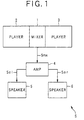
- FIG.1 is a block diagram showing the schematic configuration of the audio information outputting apparatus as the embodiment.
- an audio information outputting apparatus S is provided with a mixer 1, players 2 and 3, an amplifier 4 serving as one example of an outputting device and speakers 5 and 6.
- the players 2 and 3 may be analog players for respectively reproducing so-called analog records, or may be digital players for digitally reproducing information on a CD (Compact Discs), a DVD or the like.
- CD Compact Discs
- the mixer 1 and the players 2 and 3 are actually integrally mounted in an audio rack or the like.
- the players 2 and 3 respectively reproduce the analog records or the CDs etc., and respectively generate music composition signals including the plurality of music compositions, and then output them to the mixer 1.
- the mixer 1 synthesizes the respectively generated music composition signals in accordance with the operation of the disc jockey, generates a mixer signal Smx, and outputs it to the amplifier 4.
- the amplifier 4 amplifiers the respective music compositions included in the mixer signal Smx, generates a left signal Sol including audio information (including both of sound or tone information of an instrument or the like, and voice information of a human song or the like) to be included in a left channel and a right signal Sor including audio information to be included in a right channel, respectively, and outputs them to the speaker 5 for the left channel and the speaker 6 for the right channel, respectively.
- a left signal Sol including audio information (including both of sound or tone information of an instrument or the like, and voice information of a human song or the like) to be included in a left channel
- a right signal Sor including audio information to be included in a right channel
- the speakers 5 and 6 output the audio information, respectively included in the left signal Sol and the right signal Sor corresponding to the speakers 5 and 6, as the sound or tone to the inside of the club.
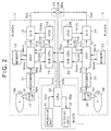
- FIG.2 is a block diagram showing the detailed configurations of the mixer 1 and the players 2 and 3 in the embodiment.
- the player 2 for reproducing an optical disc DA which is a CD or the like and on which a music composition to be reproduced is recorded, is provided with: an optical pickup 10; a decoder 11; a DSP (Digital Signal Processor) 12; a memory 13; a D/A (Digital/Analog) converter 14; a sub CPU 15 serving as one example of a reproducing device and a computer; and a VCO (Voltage Controlled Oscillator) 16.
- the player 3 for reproducing an optical disc DB which is a CD or the like and on which a music composition to be reproduced is recorded, has the configuration similar to that of the player 2.
- the player 3 is provided with: an optical pickup 20; a decoder 21; a DSP 22; a memory 23; a D/A converter 24; a sub CPU 25 serving as one example of a reproducing device and a computer; and a VCO 26.
- the mixer 1 is provided with: a CPU 30 serving as one example of a computer; an operation unit 31; a display unit 32; and an adder 33.
- the optical pickup 10 or 20 firstly drives a light source (not shown) including a semiconductor laser or the like to thereby emit a light beam B1 or B2. Then, the reception of the reflection light from the optical disc DA or DB enables the generation of a reproduction signal Spa or Spb that is an RF (Radio Frequency) signal corresponding to the music composition recorded on the optical disc DA or Db.
- the reproduction signal Spa or Spb is outputted to the decoder 11 or 21.
- the decoder 11 or 21 applies a wave form re-shaping process, a decoding process, an amplifying process and the like onto the inputted reproduction signal Spa or Spb, to thereby digitize it and generate a digital decode signal Sda or Sdb. Then, the decoder 11 or 21 outputs the generated digital decode signal Sda or Sdb to the DSP 12 or 22.
- the generation of the reproduction signal Spa or Spb in the optical pickup 10 or 20 and the generation of the digital decode signal Sda or Sdb in the decoder 11 or 21 are executed at a high speed, for example, such as a quadruple speed (i.e., four times speed) or the like.
- a quadruple speed i.e., four times speed
- the generated digital decode signal Sda or Sdb is outputted to the DSP 12 or 22 at the quadruple speed or the like.
- the DSP 12 or 22 detects a later-described BPM (Beat Per Minutes) value of the music composition to be reproduced, which is included in the inputted digital decode signal Sda or Sdb, to thereby generate a BMP signal Sbpa or Sbpb indicative of the BMP value. Then, the DSP 12 or 22 outputs the generated BMP signal Sbpa or Sbpb to the sub CPU 15 or 25, and also applies later-described various processes onto the digital decode signal Sda or Sdb in accordance with a later-described control signal Scda or Scdb from the sub CPU 15 or 25 to thereby generate a music composition signal Sra or Srb, and output it to the D/A converter 14 or 24.
- BPM Beat Per Minutes
- the DSP 12 or 22 carries out these processes while transiently storing the data necessary for these processes as a memory signal Smoa or Smob into the memory 13 or 23, and further reading out the stored data as a memory signal Smia or Smib from the memory 13 or 23.
- one series of processes from the detection of the reproduction signal Spa or Spb of the optical disc DA or DB to the storage of the memory signal Smoa or Smob into the memory 13 or 23 are performed at a high speed such as a quadruple speed (i.e., four times speed).
- the processes after reading out of the memory signal Smia or Smib from the memory 13 or 23 are performed at a low speed or a normal speed (i.e., one time speed).
- the D/A converter 14 or 24 converts the processed music composition signal Sra or Srb into an analog signal to thereby generate an analog music composition signal Saa or Sab and output it to the adder 33.
- the reading out speed at which the music composition signal Sra or Srb is read out from the DSP 12 or 22 and the digital/analog conversion frequency in the D/A converter 14 or 24 are controlled in accordance with speed control signals Sfva and Sfda from the VCO 16 or speed control signals Sfvb and Sfdb from the VCO 26, respectively.
- each of the reading out speed from the DSP 12 or 22 and the digital/analog conversion speed in the D/A converter 14 or 24 is controlled to be a normal speed (i.e., one time speed).
- the adder 33 adds the analog music composition signals Saa and Sab to thereby generate the mixer signal Smx as the output of the mixer 1, and output it to the amplifier 4 in FIG. 1.
- the sub CPU 15 or 25 generates and outputs the control signal Scda or Scdb to the DSP 12 or 22 so as to execute the later-described operation for the continuous reproductions of the music compositions, depending upon the control signal Sca or Scb from the CPU 30 and the BMP signal Sbpa or Sbpb from the DSP 12 or 22 while sending and receiving a control signal Scc between each other.
- the sub CPU 15 or 25 In parallel with those operations, the sub CPU 15 or 25 generates a control signal Scva or Scvb to control the operation of the VCO 16 or 26, and outputs it to the VCO 16 or 26, respectively.
- the VCO 16 generates and outputs the speed control signals Sfva and Sfda, respectively to the DSP 12 and the D/A converter 14, so as to control the output speed of the music composition signal Sra from the DSP 12 and the digital/analog conversion frequency of the D/A converter 14 as mentioned above.
- the VCO 26 generates and outputs the speed control signals Sfvb and Sfdb, respectively to the DSP 22 and the D/A converter 24, so as to control the output speed of the music composition signal Srb from the DSP 22 and the digital/analog conversion frequency of the D/A converter 24 as mentioned above.
- the CPU 30 generates and outputs the control signal Sca or Scb to the sub CPU 15 or 25, so as to make the sub CPU 15 or 25 execute the above-mentioned reproduction control.
- the operation for specifying the operation of the mixer 1 and the players 2 and 3 through the CPU 30 is executed by the operation unit 31.
- An operation signal Sin corresponding to this operation of specifying is outputted from the operation unit 31 to the CPU 30.
- the CPU 30 carries out the above-mentioned controls based on the operation signal Sin.
- the information with regard to the operations of the mixer 1 and the players 2 and 3 controlled by the CPU 30 is outputted from the CPU 30 as a display signal Sdp to the display unit 32, and is displayed on the display unit 32 for the disc jockey and the like.
- the DSP 12 and 22 have the configurations similar to each other and also carry out the operations similar to each other, while the memories 13 and 23 have the configurations similar to each other, and also carry out the operations similar to each other.
- the detailed configurations and operations of the DSP 12 and the memory 13 among them are respectively described in the following explanations.
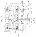
- the DSP 12 is provided with: a memory controller 35; an effect controller 36; a volume controller 37; a BPM detector 38 serving as one example of a detecting device, a first detecting device and a second detecting device; and a data output controller 39.
- the DSP 12 is actually formed as one LSI (Large Scale Integrated circuit). These controllers are respectively defined as respective functions in the LSI chip.
- the memory 13 is provided with: a cue memory 40; a ring buffer memory 41; and an effect memory 42.
- each of the cue memory 40, the ring buffer memory 41 and the effect memory 42 is defined as a part of a memory area in the memory 13.
- the BPM detector 38 detects the number of beats per minute of the music composition included in the inputted digital decode signal Sda (hereafter, the number of beats per minute is merely referred to as a "BPM value") to thereby generate the BPM signal Sbpa and output it to the sub CPU 15.
- a process of detecting the BPM value in the BPM detector 38 is actually a process of continuing to detect an interval between the beats of the music composition for a certain time duration, and detecting the BPM value in accordance with the statistic of the beat intervals detected within the certain time duration.
- a process of automatically detecting the BPM value is performed by using a time counter as following. Namely, time-counting of the time counter is started at one time point when the level of a predetermined frequency component of the inputted audio signal exceeds a predetermined threshold level, and is stopped at another time point when the level of the frequency component exceed the threshold level again after a predetermined time duration has elapsed from the one time point.
- the time-counted value is converted to the number of the beats for a predetermined unit time period to thereby obtain the BPM value.
- Such a process of automatically detecting the BPM value by using a time counter is known and is disclosed in a range between the paragraph numbers [0010] to [0027] and a range from FIG.1 to FIG.9 in Japanese Patent Application Laid Open Publication No. Hei. 8-201542, for example.
- the process of detecting the BPM value is a process of detecting a beat timing, which is defined as a timing when a beat of each music composition (including both of the strong beat and the weak beat) is generated.
- the cue memory 40 within the memory 13 is a memory for storing therein in advance the digital decode signal Sda corresponding to the head portion of a music composition to be next reproduced by the player 2, in order to compensate a transient interruption of the sound or tone due to the time required for optically reading out the data from the optical disc DA (occurring when a reproduction of a new music composition is started).
- the digital decode signal Sda corresponding to two seconds at the head portion of the music composition to be next reproduced as the memory amount of the digital decode signal Sda is stored into the cue memory 40.
- the ring buffer memory 41 within the memory 13 is a memory for transiently storing therein the digital decode signal Sda corresponding to the music composition to be currently reproduced.
- the digital decode signal Sda is stored sequentially from the head thereof. Then, after all the memory areas within the ring buffer memory 41 are filled with the digital decode signals Sda, rewriting to replace the storage content by the digital decode signal Sda to be next stored from the head of the memory areas is repeated cyclically for the digital decode signal Sda corresponding to one music composition on the whole.
- the effect memory 42 within the memory 13 is used to store therein the digital decode signal Sda, as the occasion demands, when the condition of the connection between the music compositions in the continuous reproduction of the music compositions is changed.
- the memory controller 35 In accordance with a control signal Scm included in the control signal Scda outputted by the sub CPU 15, the memory controller 35 outputs and stored the inputted digital decode signal Sda into the cue memory 40 as a memory signal Scmo, as the occasion demands. Also, the memory controller 35 outputs and stores it into the ring buffer memory 41 as a memory signal Sro.
- the memory controller 35 reads out the digital decode signal Sda stored in the cue memory 40 or the ring buffer memory 41, as a memory signal Scmi or Sri, respectively as the occasion demands, and then outputs it as a reading out signal Smc to the effect controller 36.
- the effect controller 36 outputs and stores the inputted reading out signal Smc as a memory signal Seo into the effect memory 42, as the occasion demands. Also, while reading it out as a memory signal Sei fro the effect memory 42, the effect controller 36 applies a process required to change the above-mentioned connection condition between the music compositions (hereafter, referred to as a "connection pattern") onto the reading out signal Smc, to thereby generate an effect signal Se and output it to the volume controller 37.
- connection pattern a process required to change the above-mentioned connection condition between the music compositions
- the effect signal Se is generated only when the connection between the music compositions is to be done. Except for the timing to do such a connection, the inputted reading out signal Smc (in other words, the digital decode signal Sda) is outputted to the volume controller 37 as it is.
- Each of the memory signals Scmo, Sro, and Seo corresponds to the memory signal Smoa in FIG.2.
- Each of the memory signals Scmi, Sri and Sei corresponds to the memory signal Smia in FIG.2.
- the volume controller 37 adjusts a level of the effect signal Se or the reading out signal Smc by using a conventional method in accordance with a control signal Scv included in the control signal Scda outputted from the sub CPU 15, to thereby generate a level adjusted signal Sv and output it to the data output controller 39.
- the data output controller 39 controls an output rate (in other words, the BPM value (or tempo) of the music composition included in the music composition signal Sra) when the inputted level adjusted signal Sv is outputted as the music composition signal Sra as described later, in accordance with the speed control signal Sfva from the VCO 16, to thereby generate the music composition signal Sra at the controlled output rate and output it to the D/A converter 14 in FIG. 2.
- the data output controller 39 controls the frequency of a clock signal for controlling the output rate of the music composition signal Sra, to a value indicated by the speed control signal Sfva, so as to control the output rate of the music composition signal Sra.
- FIG.4 is a flowchart showing the reproduction control process
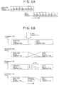
- FIGs.5A and 5B are diagrams showing the connection pattern between the music compositions.
- the longitudinal length of each stage in FIG.5B denotes a reproduction level of each music composition.
- the memory controller 35 starts the processes of generating the digital decode signal Sda corresponding to the head portion of a music composition to be firstly reproduced, and storing it into the cue memory 40. Also the memory controller 35 starts the process of storing the digital decode signals Sda corresponding to the portions after the head portion into the ring buffer memory 41 in the reproduction order. Moreover, the memory controller 35 generates the music composition signal Sra or Srb, and continues to output the corresponding music composition (Step S1).
- Step S2 the BPM value in the music composition currently being reproduced and outputted is detected, and the beat timing of the music composition is also detected.
- the processes of detecting the beat timing and the BPM value at the step S2 are done by using the memory 13 or 23 etc., within the player, which is currently reproducing the music composition.
- the head portion of the music composition which is to be reproduced continuously after the music composition currently being reproduced and outputted, is searched (i.e., a so-called "head search” is performed) on the optical disc DA or DB (hereafter, this music composition being searched is referred to as a "next music composition").
- the detections of the beat timing and the BPM value of the next music composition are respectively performed (Step S3).
- the processes of carrying out the head search of the next music composition and detecting the BPM value at the step S3 are done by using the memory 13 or 23 etc., within the player, which is currently reproducing the music composition, if the next music composition is recorded on the optical disc DA or DB, on which the music composition currently being reproduced and outputted is recorded. On the contrary, if the next music composition is recorded on the optical disc DB or DA different from the optical disc DA or DB, on which the music composition currently being reproduced and outputted is recorded, the processes at the step S3 are done by using the memory 23 or 13 etc., within the player different from the player, which is currently reproducing the music composition.
- Step S4 it is judged whether or not the beat timing of the music composition that is currently reproduced and outputted has been actually detected at the step S2 (Step S4). If the beat timing has never been detected (Step S4: NO), it is further judged whether or not the timing when the next music composition is to be outputted has just come (Step S5).
- the judgment at the step S5 is done in accordance with whether or not a predetermined time duration has elapsed from the start of the output of the music composition currently being reproduced and outputted, in the normal process of controlling the continuous reproduction. On the other hand, for example, if a continuous reproduction for only initial one minute in each music composition is set in advance, the judgment at the step S5 is done in accordance with whether or not one minute has elapsed from the start of the output of the music composition currently being reproduced and outputted.
- Step S5 if the timing of reproducing and outputting the next music composition has never come in the judgment at the step S5 (Step S5: NO), the operational flow returns back to the step S4, so that it is checked whether or not the beat timing has been detected while continuing to reproduce the current music composition. On the other hand, if the timing of reproducing and outputting the next music composition has just come (Step S5: YES), the operational flow proceeds to a step S7 as it is.
- Step S4 YES
- Step S6 it is judged whether or not the timing of reproducing and outputting the next music composition has come, in accordance with a count value of the detected beat timing, similarly to the step S5 (Step S6).
- step S6 it is judged whether or not a predetermined number of beats has been counted from the start of the output of the music composition currently being reproduced and outputted, in accordance with the count value of the detected beat timing, in the normal process of controlling the continuous reproduction.
- the continuous reproduction for only initial one minute in each music composition is set in advance, it is judged whether or not the amount corresponding to, for example, 128 beats (which is a length corresponding to approximately one minute in a case that a length of one beat is 0.5 second for a dance music composition of a quadruple time) has been counted from the start of the output of the music composition currently being reproduced and outputted.
- Step S6 If the timing of reproducing and outputting the next music composition has never come yet in the judgment at the step S6 (Step S6: NO), the operational flow returns back to the step S4, and continues to reproduce the current music composition. On the other hand, if the timing of reproducing and outputting the next music composition has just come (Step S6: YES), it is next judged whether or not a preparation to start reproducing the next music composition is completed (actually, whether or not the digital decode signal Sda corresponding to the head portion of the next music composition is stored in the cue memory 40) (Step S7).
- Step S9 the operational flow proceeds to a step S12 in order to start reproducing the next music composition without considering the connectivity of rhythm.
- Step S9 the BPM value of the next music composition has been actually detected
- Step S10 it is next judged whether or not the music composition, which is to be reproduced as the next music composition, is recorded on the optical disc DA or DB different from that on which the music composition currently reproduced and outputted is recorded (Step S10).
- Step S10 if the next music composition is not recorded on the optical disc DA or DB different from that on which the music composition currently being reproduced and outputted is recorded i.e., recorded on the same optical disc DA or DB (Step S10: NO), the operational flow proceeds to the step S12 in order to start reproducing the next music composition.
- Step S10 if the next music composition is recorded on the optical disc DA or DB different from that on which the music composition currently being reproduced and outputted is recorded (Step S10; YES), the BPM value of the next music composition recorded on the different optical disc DB or DA is set so as to coincide with the BPM value of the music composition currently being reproduced and outputted (Step S11).
- the process at the step S11 is executed by the data output controller 39 within the player which is to reproduce the next music composition.
- Step S12 it is next judged whether or not the beat timing when the reproduction of the next music composition is to be started has come.
- this step S12 if the beat timing of the music composition currently being reproduced and outputted has been detected, it is judged so as to start the reproduction output of the next music composition immediately after the elapse of the time corresponding to one beat from the start of the final beat (for example, a 128-th beat) of the music composition currently reproduced and outputted (e.g., start it at the timing of the 129-th beat) (refer to FIG.5A).
- the digital decode signal Sda is read out and outputted at a corresponding timing from the cue memory 40 which stores the head portion of the next music composition.
- step S12 if the beat timing of the music composition currently being reproduced and outputted has never been detected, it is judged so as to start reproducing the next music composition by reading out the content of the cue memory 40 corresponding to the next music composition, immediately after the end of the current music composition.
- Step S12 if the beat timing when the reproduction of the next music composition is to be started has never come yet (Step S12: NO), the operational flow waits for the beat timing. On the other hand, if the beat timing has just come (Step S12: YES), the connection pattern is selected in accordance with a predetermined procedure in case that the next music composition is to be actually connected to the music composition currently being reproduced and outputted (Step S13).
- one connection pattern is selected from, for example, four kinds of connection patterns as shown in FIG.5B.
- connection pattern shown on a top stage of FIG.5B is referred to as a so-called "cut in pattern", which is a connection pattern to start the reproduction output of the next music composition simultaneously with an end of a previous music composition (i.e., the music composition currently being reproduced and outputted).
- the reproduction start of the next music composition is controlled so as to start the beat of the next music composition (refer to FIG.5A) in time to match the beat timing of the previous music composition as described later (refer to the step S12).
- a connection pattern shown on a second stage from the top stage of FIG.5B is referred to as a so-called "cross fade pattern", in which the connection is done as follows. That is, a fade-out is performed on the previous music composition for a predetermined period, and it is ended. Then, a fade-in for the next music composition is started from a timing when the fade-out is started. The fade-in for the next music composition is completed at a timing when the fade-out for the previous music composition is ended. Thus, the reproduction level is kept at a natural level.
- a connection pattern shown on a second stage from a bottom stage of FIG.5B is referred to as a so-called "echo pattern", in which the connection is doe as follows. That is, when the reproduction output of the previous music composition is ended, a portion of a music composition corresponding to a final beat in the previous music composition is repeated in time to match the beat timing of the previous music composition, and the reproduction level is gradually dropped to then carry out the reproduction. Then, the reproduction of the next music composition is started when the reproduction level in the repetition decreases to a zero level. In this echo pattern, the rhythms at the time of the connection can be continuously connected by starting the reproduction of the next music composition so as to coincide with the beat timing of the previous music composition.
- the previous music composition is ended while the portion of the music composition corresponding to the final beat of the previous music composition is repeatedly reproduced and outputted by the operations of the effect controller 36 and the effect memory 42.
- connection pattern shown on the bottom stage of FIG.5B is referred to as a so-called "zip pattern", in which the connection pattern is done as follows. That is, when the reproduction output of the previous music composition is ended, a musical interval or distance of the previous music composition is gradually made down, and the reproduction level of the previous music composition is finally dropped to the zero level. Then, the reproduction of the next music composition is started in time to match the beat timing of the previous music composition from the timing of the zero level. In this zip pattern, when the previous music composition is ended, such a change on the acoustic feeling that a rotation of a so-called analog record is gradually stopped can be obtained.
- the musical interval or distance (a so-called "key” of a music composition) is gradually made down by the operations of the effect controller 36 and the effect memory 42, and the previous music composition is ended.
- connection pattern is selected at the step S13, it is next judged whether or not the selected connection pattern is the cut in pattern (Step S14).
- Step S14 the connection to the next music composition is done through another connection pattern (Step S15), and the operational flow proceeds to a step S17.
- Step S14 if the selected connection pattern is the cut in pattern (Step S14: YES), the music composition is ended at the final beat timing of the music composition currently being reproduced and outputted. At the same time, the reproduction output of the next music composition is started from the beginning of the beat timing of the next music composition (Step S16). In this case, if the next music composition is recorded on the optical disc DA or DB same as that on which the previous music composition is recorded, the reproduction of the next music composition is started after the BPM value of the next music composition is set so as to coincide with the BPM value of the previous music composition at the timing of the reproduction output.
- Step S17 When the reproduction of the next music composition is started, it is judged whether or not an operation indicative of the end of the auto mix mode shown in FIG.4 is executed through the operation unit 31 (Step S17). If it is executed (Step S17: YES), the process of controlling the continuous reproduction is ended as it is. On the other hand, if it is not executed and the operation based on the auto mix mode is to be continued (Step S17: NO), the operational flow returns back to the step S3, and the above-mentioned operations are performed on the next music composition whose reproduction is started.
- Step S7 If the preparation for the next music composition is not completed at the step S7 (Step S7: NO), the next music composition is forcedly set (Step S8), and the operational flow proceeds to the step S9.
- the digital decode signal Sda corresponding to the head portion of the next music composition based on the record order within the optical disc DA or DB is accumulated in the cue memory 40, and it remains on standby.
- the digital decode signal Sda corresponding to the head portion of the next music composition based on the record order within the optical disc DA or DB that is currently placed on any of the players 2 or 3 is accumulated in the cue memory 40, and it remains on standby.
- the operational flow returns back to the first music composition in the predetermined order. Then, the digital decode signal Sda corresponding to the head portion of the first music composition is accumulated in the cue memory 40, and it remains on standby.
- the continuous reproduction controlling process of the embodiment since the time period required for one beat of the next music composition is controlled to be coincident with that of the previous music composition, and the next music composition is reproduced under such a condition (refer to the steps S11 and S16), it is possible to continuously reproduce the music compositions automatically while the rhythms of the respective music compositions are consistent by means of a relatively simple operation.
- next music composition is continuously reproduced while the beat timing of the next music composition is controlled to be coincident with that of the previous music composition (refer to FIG. 5A), it is possible to continuously reproduce the respective music compositions while making the rhythms of the respective music compositions consistent by a relatively simple operation.
- the next music composition is continuously reproduced as it is, it is possible to prevent the continuous reproduction of the respective music compositions from being interrupted as the time period required for one beat of the next music composition cannot be detected.
- the next music composition is reproduced continuously to the previous music composition as it is from the timing set in advance, it is possible to prevent the continuous reproduction of the respective music compositions from being interrupted as the beat timing of the previous music composition cannot be detected.
- the connection of a weak beat or a middle strong beat of the next music composition to a weak beat of the previous music composition also enables the connection between the music compositions.
- the present invention is applied to the audio information outputting apparatus S including the two players 2 and 3.
- the present invention can be applied to the case in which an audio information outputting apparatus including three or more players reproduces and outputs a music composition, after a music composition that is reproduced and outputted from one player, in parallel from the other two or more players.
- a program corresponding to the flow chart shown in FIG.4 is stored in a flexible disc serving as one example of an information record medium etc., and then it is read out and executed by the CPU 30 or the sub CPU 15 and 25.
- a computer program may be downloaded to the audio information outputting apparatus S through a network such as an internet.
Landscapes
- Engineering & Computer Science (AREA)
- Multimedia (AREA)
- Signal Processing (AREA)
- Physics & Mathematics (AREA)
- Acoustics & Sound (AREA)
- Signal Processing For Digital Recording And Reproducing (AREA)
- Signal Processing Not Specific To The Method Of Recording And Reproducing (AREA)
- Indexing, Searching, Synchronizing, And The Amount Of Synchronization Travel Of Record Carriers (AREA)
- Electrophonic Musical Instruments (AREA)
Abstract
Description
Claims (12)
- An apparatus (S) for reproducing audio information, which reproduces one audio information and reproduces another audio information after said one audio information, characterized in that said apparatus comprises:a detecting device (12, 38) for detecting one time period required for one beat of said one audio information, and also detecting another time period for one beat of said another audio information; anda reproducing device (15) for reproducing said another audio information continuously to said one audio information while controlling said detected another time period to be coincident with said detected one time period.
- An apparatus (S) for reproducing audio information, which reproduces one audio information and reproduces another audio information after said one audio information, characterized in that said apparatus comprises:a detecting device (12, 38) for detecting one beat timing which is a timing of a beat of said one audio information and also detecting another beat timing which is a timing of a beat of said another audio information; anda reproducing device (15) for reproducing said another audio information continuously to said one audio information while controlling said detected another beat timing to be coincident with said detected one beat timing.
- An apparatus (S) according to claim 2, characterized in that said detecting device (12, 38) detects a timing of a strong beat of said one audio information as said one beat timing, and also detects a timing of a strong beat of said another audio information as said another beat timing.
- An apparatus (S) for reproducing audio information, which reproduces one audio information and reproduces another audio information after said one audio information, characterized in that said apparatus comprises:a first detecting device (12, 38) for detecting one time period required for one beat of said one audio information, and also detecting another time period for one beat of said another audio information;a second detecting device (12, 38) for detecting one beat timing which is a timing of a beat of said one audio information and also detecting another beat timing which is a timing of a beat of said another audio information; anda reproducing device (15) for reproducing said another audio information continuously to said one audio information while controlling said detected another time period to be coincident with said detected one time period and also controlling said detected another beat timing to be coincident with said detected one beat timing.
- An apparatus (S) according to claim 1 or 4, characterized in that said reproducing device (15) reproduces said another audio information as it is continuously to said one audio information in case that said detecting device (12, 38) cannot detect said another time period.
- An apparatus (S) according to claim 2 or 4, characterized in that said reproducing device (15) reproduces said another audio information as it is from a predetermined timing set in advance continuously to said one audio information in case that said detecting device cannot detect said another beat timing.
- A method of reproducing audio information, which reproduces one audio information and reproduces another audio information after said one audio information, characterized in that said method comprises:a detecting process of detecting one time period required for one beat of said one audio information, and also detecting another time period for one beat of said another audio information; anda reproducing process of reproducing said another audio information continuously to said one audio information while controlling said detected another time period to be coincident with said detected one time period.
- A method of reproducing audio information, which reproduces one audio information and reproduces another audio information after said one audio information, characterized in that said method comprises:a detecting process of detecting one beat timing which is a timing of a beat of said one audio information and also detecting another beat timing which is a timing of a beat of said another audio information; anda reproducing process of reproducing said another audio information continuously to said one audio information while controlling said detected another beat timing to be coincident with said detected one beat timing.
- A method according to claim 8, characterized in that said detecting process detects a timing of a strong beat of said one audio information as said one beat timing, and also detects a timing of a strong beat of said another audio information as said another beat timing.
- A computer program tangibly embodying a program of instructions executable by a computer to perform processes to reproduce one audio information and reproduce another audio information after said one audio information, characterized in that said processes comprise:a detecting process of detecting one time period required for one beat of said one audio information, and also detecting another time period for one beat of said another audio information; anda reproducing process of reproducing said another audio information continuously to said one audio information while controlling said detected another time period to be coincident with said detected one time period.
- A computer program tangibly embodying a program of instructions executable by a computer to perform processes to reproduce one audio information and reproduce another audio information after said one audio information, characterized in that said processes comprise:a detecting process of detecting one beat timing which is a timing of a beat of said one audio information and also detecting another beat timing which is a timing of a beat of said another audio information; anda reproducing process of reproducing said another audio information continuously to said one audio information while controlling said detected another beat timing to be coincident with said detected one beat timing.
- A computer program according to claim 11, characterized in that said detecting process detects a timing of a strong beat of said one audio information as said one beat timing, and also detects a timing of a strong beat of said another audio information as said another beat timing.
Applications Claiming Priority (2)
| Application Number | Priority Date | Filing Date | Title |
|---|---|---|---|
| JP11220214A JP2001052441A (en) | 1999-08-03 | 1999-08-03 | Audio information reproducing method and apparatus, and information recording medium |
| JP22021499 | 1999-08-03 |
Publications (2)
| Publication Number | Publication Date |
|---|---|
| EP1077548A2 true EP1077548A2 (en) | 2001-02-21 |
| EP1077548A3 EP1077548A3 (en) | 2004-05-06 |
Family
ID=16747681
Family Applications (1)
| Application Number | Title | Priority Date | Filing Date |
|---|---|---|---|
| EP00116206A Withdrawn EP1077548A3 (en) | 1999-08-03 | 2000-08-03 | Method of and apparatus for mixing and reproducing audio information from two sources, and computer program for implementing the method |
Country Status (3)
| Country | Link |
|---|---|
| US (1) | US6538190B1 (en) |
| EP (1) | EP1077548A3 (en) |
| JP (1) | JP2001052441A (en) |
Cited By (1)
| Publication number | Priority date | Publication date | Assignee | Title |
|---|---|---|---|---|
| FR2963980A1 (en) * | 2011-03-15 | 2012-02-24 | Continental Automotive France | Digital audio signal mixer for buzzer in silent electric vehicle, has blockers conserving data read by readers, and first-order filter transforming one-bit digital signal from one-bit sigma-delta converter into final analog audio signal |
Families Citing this family (10)
| Publication number | Priority date | Publication date | Assignee | Title |
|---|---|---|---|---|
| JP3869175B2 (en) * | 2000-02-07 | 2007-01-17 | 株式会社コナミデジタルエンタテインメント | GAME DEVICE, GAME MUSIC OUTPUT METHOD, INFORMATION STORAGE MEDIUM, GAME PROGRAM DISTRIBUTION DEVICE, AND GAME PROGRAM DISTRIBUTION METHOD |
| JP3712679B2 (en) * | 2001-02-08 | 2005-11-02 | 株式会社ソニー・コンピュータエンタテインメント | Information processing program, recording medium recording information processing program, program execution device, and information expression method |
| JP4646099B2 (en) * | 2001-09-28 | 2011-03-09 | パイオニア株式会社 | Audio information reproducing apparatus and audio information reproducing system |
| JP4134945B2 (en) * | 2003-08-08 | 2008-08-20 | ヤマハ株式会社 | Automatic performance device and program |
| CN1971522A (en) * | 2005-11-26 | 2007-05-30 | 鸿富锦精密工业(深圳)有限公司 | System and method for making single-tone spectrum scan waveform file |
| EP2141705A4 (en) * | 2007-03-30 | 2013-01-23 | Pioneer Corp | Reproducing apparatus and program |
| US9070352B1 (en) | 2011-10-25 | 2015-06-30 | Mixwolf LLC | System and method for mixing song data using measure groupings |
| US9111519B1 (en) | 2011-10-26 | 2015-08-18 | Mixwolf LLC | System and method for generating cuepoints for mixing song data |
| JP6019803B2 (en) * | 2012-06-26 | 2016-11-02 | ヤマハ株式会社 | Automatic performance device and program |
| JP7375002B2 (en) * | 2019-05-14 | 2023-11-07 | AlphaTheta株式会社 | Sound equipment and music playback program |
Family Cites Families (8)
| Publication number | Priority date | Publication date | Assignee | Title |
|---|---|---|---|---|
| JPS60166892A (en) | 1984-02-10 | 1985-08-30 | 株式会社日立製作所 | steam relief valve |
| GB8629043D0 (en) * | 1986-12-04 | 1987-01-14 | Denner M J | Audio deck controller |
| US5734731A (en) * | 1994-11-29 | 1998-03-31 | Marx; Elliot S. | Real time audio mixer |
| JP3373315B2 (en) | 1995-01-20 | 2003-02-04 | パイオニア株式会社 | Beat detection device |
| JP2927229B2 (en) * | 1996-01-23 | 1999-07-28 | ヤマハ株式会社 | Medley playing equipment |
| JP3399297B2 (en) * | 1997-05-22 | 2003-04-21 | ヤマハ株式会社 | Electronic musical instrument |
| US5869783A (en) * | 1997-06-25 | 1999-02-09 | Industrial Technology Research Institute | Method and apparatus for interactive music accompaniment |
| JP3799761B2 (en) * | 1997-08-11 | 2006-07-19 | ヤマハ株式会社 | Performance device, karaoke device and recording medium |
-
1999
- 1999-08-03 JP JP11220214A patent/JP2001052441A/en active Pending
-
2000
- 2000-08-03 US US09/631,957 patent/US6538190B1/en not_active Expired - Lifetime
- 2000-08-03 EP EP00116206A patent/EP1077548A3/en not_active Withdrawn
Cited By (1)
| Publication number | Priority date | Publication date | Assignee | Title |
|---|---|---|---|---|
| FR2963980A1 (en) * | 2011-03-15 | 2012-02-24 | Continental Automotive France | Digital audio signal mixer for buzzer in silent electric vehicle, has blockers conserving data read by readers, and first-order filter transforming one-bit digital signal from one-bit sigma-delta converter into final analog audio signal |
Also Published As
| Publication number | Publication date |
|---|---|
| US6538190B1 (en) | 2003-03-25 |
| JP2001052441A (en) | 2001-02-23 |
| EP1077548A3 (en) | 2004-05-06 |
Similar Documents
| Publication | Publication Date | Title |
|---|---|---|
| US7982120B2 (en) | Performance apparatus and storage medium therefor | |
| KR100283134B1 (en) | Karaoke apparatus and method for generating speech effects matching music | |
| JP4646099B2 (en) | Audio information reproducing apparatus and audio information reproducing system | |
| CN100481248C (en) | Reproducing device | |
| JPH10149179A (en) | Karaoke system | |
| US6608803B2 (en) | Recording medium reproduction apparatus | |
| US6538190B1 (en) | Method of and apparatus for reproducing audio information, program storage device and computer data signal embodied in carrier wave | |
| US6630621B1 (en) | Apparatus and method for sampling and storing music, and apparatus for outputting music | |
| EP1077549B1 (en) | Method of and apparatus for mixing and reproducing audio information from two sources, and computer program for implementing the method | |
| EP1074990B1 (en) | Method of and apparatus for reproducing audio information and computer program therefor | |
| JP4123583B2 (en) | Karaoke equipment | |
| JP3178694B2 (en) | Karaoke equipment | |
| JP4081859B2 (en) | Singing voice generator and karaoke device | |
| JP2002244677A (en) | Audio reproducing device | |
| CN101383146B (en) | Reproducing device | |
| JP2548723Y2 (en) | Music playback device | |
| JP3432771B2 (en) | Karaoke equipment | |
| EP1073055A2 (en) | Apparatus and method for reproducing audio information | |
| JPH02101691A (en) | Introduction scanning method | |
| JPH11119785A (en) | Karaoke device | |
| JP2539362Y2 (en) | Electronic musical instrument | |
| JPH06214565A (en) | Recording medium reproducing device | |
| JPS5956270A (en) | Reproducing device of accompanying music | |
| JPH04278258A (en) | Acoustic circuit | |
| JP2539362Z (en) |
Legal Events
| Date | Code | Title | Description |
|---|---|---|---|
| PUAI | Public reference made under article 153(3) epc to a published international application that has entered the european phase |
Free format text: ORIGINAL CODE: 0009012 |
|
| AK | Designated contracting states |
Kind code of ref document: A2 Designated state(s): AT BE CH CY DE DK ES FI FR GB GR IE IT LI LU MC NL PT SE |
|
| AX | Request for extension of the european patent |
Free format text: AL;LT;LV;MK;RO;SI |
|
| PUAL | Search report despatched |
Free format text: ORIGINAL CODE: 0009013 |
|
| AK | Designated contracting states |
Kind code of ref document: A3 Designated state(s): AT BE CH CY DE DK ES FI FR GB GR IE IT LI LU MC NL PT SE |
|
| AX | Request for extension of the european patent |
Extension state: AL LT LV MK RO SI |
|
| 17P | Request for examination filed |
Effective date: 20040715 |
|
| 17Q | First examination report despatched |
Effective date: 20041118 |
|
| AKX | Designation fees paid |
Designated state(s): DE ES FR GB IT NL |
|
| STAA | Information on the status of an ep patent application or granted ep patent |
Free format text: STATUS: THE APPLICATION IS DEEMED TO BE WITHDRAWN |
|
| 18D | Application deemed to be withdrawn |
Effective date: 20080301 |