EP1077510A2 - Electrical connector - Google Patents
Electrical connector Download PDFInfo
- Publication number
- EP1077510A2 EP1077510A2 EP00306799A EP00306799A EP1077510A2 EP 1077510 A2 EP1077510 A2 EP 1077510A2 EP 00306799 A EP00306799 A EP 00306799A EP 00306799 A EP00306799 A EP 00306799A EP 1077510 A2 EP1077510 A2 EP 1077510A2
- Authority
- EP
- European Patent Office
- Prior art keywords
- fixing ring
- connector
- rotational direction
- housings
- ring
- Prior art date
- Legal status (The legal status is an assumption and is not a legal conclusion. Google has not performed a legal analysis and makes no representation as to the accuracy of the status listed.)
- Granted
Links
- 230000013011 mating Effects 0.000 claims abstract description 6
- 230000004308 accommodation Effects 0.000 description 9
- 239000002184 metal Substances 0.000 description 8
- 230000002093 peripheral effect Effects 0.000 description 6
- 229920003002 synthetic resin Polymers 0.000 description 3
- 239000000057 synthetic resin Substances 0.000 description 3
- 238000013459 approach Methods 0.000 description 2
- 238000010276 construction Methods 0.000 description 2
- 238000002360 preparation method Methods 0.000 description 2
- 238000000638 solvent extraction Methods 0.000 description 2
- 230000006835 compression Effects 0.000 description 1
- 238000007906 compression Methods 0.000 description 1
- 238000012986 modification Methods 0.000 description 1
- 230000004048 modification Effects 0.000 description 1
- 238000000926 separation method Methods 0.000 description 1
Images




Classifications
-
- H—ELECTRICITY
- H01—ELECTRIC ELEMENTS
- H01R—ELECTRICALLY-CONDUCTIVE CONNECTIONS; STRUCTURAL ASSOCIATIONS OF A PLURALITY OF MUTUALLY-INSULATED ELECTRICAL CONNECTING ELEMENTS; COUPLING DEVICES; CURRENT COLLECTORS
- H01R13/00—Details of coupling devices of the kinds covered by groups H01R12/70 or H01R24/00 - H01R33/00
- H01R13/62—Means for facilitating engagement or disengagement of coupling parts or for holding them in engagement
- H01R13/622—Screw-ring or screw-casing
-
- H—ELECTRICITY
- H01—ELECTRIC ELEMENTS
- H01R—ELECTRICALLY-CONDUCTIVE CONNECTIONS; STRUCTURAL ASSOCIATIONS OF A PLURALITY OF MUTUALLY-INSULATED ELECTRICAL CONNECTING ELEMENTS; COUPLING DEVICES; CURRENT COLLECTORS
- H01R13/00—Details of coupling devices of the kinds covered by groups H01R12/70 or H01R24/00 - H01R33/00
- H01R13/62—Means for facilitating engagement or disengagement of coupling parts or for holding them in engagement
- H01R13/627—Snap or like fastening
- H01R13/6271—Latching means integral with the housing
-
- H—ELECTRICITY
- H01—ELECTRIC ELEMENTS
- H01R—ELECTRICALLY-CONDUCTIVE CONNECTIONS; STRUCTURAL ASSOCIATIONS OF A PLURALITY OF MUTUALLY-INSULATED ELECTRICAL CONNECTING ELEMENTS; COUPLING DEVICES; CURRENT COLLECTORS
- H01R13/00—Details of coupling devices of the kinds covered by groups H01R12/70 or H01R24/00 - H01R33/00
- H01R13/62—Means for facilitating engagement or disengagement of coupling parts or for holding them in engagement
- H01R13/629—Additional means for facilitating engagement or disengagement of coupling parts, e.g. aligning or guiding means, levers, gas pressure electrical locking indicators, manufacturing tolerances
- H01R13/633—Additional means for facilitating engagement or disengagement of coupling parts, e.g. aligning or guiding means, levers, gas pressure electrical locking indicators, manufacturing tolerances for disengagement only
- H01R13/635—Additional means for facilitating engagement or disengagement of coupling parts, e.g. aligning or guiding means, levers, gas pressure electrical locking indicators, manufacturing tolerances for disengagement only by mechanical pressure, e.g. spring force
Definitions
- the present invention relates to an electrical connector in which a pair of connector housings containing electrical terminals are fitted to each other, typically with a relatively low force.
- a connector is used for example to connect wire bundles in a motor vehicle.
- JP-A-4-132178 An example of a connector of this type is disclosed in JP-A-4-132178.
- the connector has a pair of female and male circular cross-section connector housings to be fitted to each other.
- a fixing ring is installed on a peripheral surface of the female housing such that the fixing ring is freely rotatable.
- a follower pin projects inwardly from the fixing ring.
- a cam groove is formed on a peripheral surface of the male housing. The housings are temporarily fitted to each other by engaging the follower pin to the cam groove. Then, the fixing ring is rotated, and as a result the housings arrive at the fully fitted state by the camming action of the follower pin in the cam groove.
- the fixing ring is rotated to a predetermined position and locked, and an operator then determines if the housings are fully fitted.
- fitting resistance may be generated (although the degree of the resistance is generally low).
- the operator stops rotating the fixing ring before the housings are fully fitted That is, the housings may be held in an incompletely fitted state. It may be very difficult for the operator to detect this.
- the present invention provides a connector having first and second matable connector housings with circular cross-sections, and a fixing ring which is rotatably mounted at an outer circumference of the first connector housing.
- the fixing ring is engaged with the second connector housing to form a screw-action cam mechanism which draws the connector housings into mating engagement when the fixing ring is rotated in a first rotational direction relative to the connector housings.
- the connector further has a detent for detaining the fixing ring at a predetermined position corresponding to full mating engagement of the connector housings, and at least one return spring which applies a return bias to the fixing ring in a second rotational direction opposite to said first rotational direction as the fixing ring is rotated in the first rotational direction.
- the return spring is a coil spring which is accommodated in a circumferential groove formed in the first connector housing inwardly of the fixing ring, and a loading member is operably connectable to the fixing ring and projects into the circumferential groove, so that when the fixing ring is rotated in the first rotational direction the loading member travels around the circumferential groove to load the coil spring and generate the return bias.
- the loading member projects inwardly from a loading ring which is rotatably mounted between the fixing ring and the circumferential groove, the fixing ring having a resiliently deformable latching arm which is engageable with a corresponding portion of the loading ring to operably connect the loading member to the fixing ring, the detent being provided by the latching arm and a locking projection formed on the first connector housing, whereby, when the fixing ring reaches the predetermined position of full engagement, to detain the fixing ring the latching arm engages the locking projection with a latching action which involves a deformation of the latching arm, the deformation also disengaging the latching arm from the corresponding portion of the loading ring to release the coil spring and at least partially remove the return bias.
- the latching arm and locking projection are adapted so that when at least a predetermined force is applied to the fixing ring to rotate the fixing ring in the opposite rotational direction, the latching arm disengages from the locking projection.
- the connector housings are fitted to each other.
- the fixing ring when released rotates in the opposite direction by the elastic restoring force of the return spring stored so that the connector housings separate from each other. Thereby, it is possible to detect whether the housings are fully engaged.
- the connector has a male connector housing 10 (hereinafter referred to as male housing 10) and a female connector housing 20 (hereinafter referred to as female housing 20) to be fitted in the male housing 10.
- male housing 10 hereinafter referred to as male housing 10
- female housing 20 to be fitted in the male housing 10.
- each of the male and female housings 10 and 20 which is fitted to the other housing is called the front side.
- the male housing 10 is formed by combining two pieces made of synthetic resin with each other.
- the male housing 10 has a body part 11 of circular cross-section and a cylindrical hood part 12 projecting forward from the body part 11.
- the male housing 10 is shown installed on an installing hole 17 of a panel 16 in preparation for engagement with the female housing 20.
- a plurality of cavities 13 is formed in the body part 11.
- Male terminal metal fittings (not shown) are inserted into respective cavities 13 from the rear end thereof and are held therein to provide tabs which project into the hood part 12.
- the male terminal metal fittings are locked by retainers 14 to prevent removal of the fittings from the cavities 13.
- the female housing 20 is also made of synthetic resin and is of general circular cross-section.
- the front side of the female housing 20 can be fitted in the hood part 12 of the male housing 10.
- a plurality of cavities 21 is formed in the female housing 20 such that the cavities 21 confront the cavities of the male housing 10.
- Female terminal metal fittings (not shown) are inserted into respective cavities 21 from the rear end thereof and are held therein. The female terminal metal fittings are locked by retainers 22 to prevent removal of the fittings from the cavities 21.
- An outer circumferential seal ring 24 is installed midway along the female housing 20.
- the seal ring 24 is elastically sandwiched between the outer surface of the female housing 20 and the front side of the hood part 12 (see Fig. 2).
- a fixing ring 30 is also made of synthetic resin and is cylindrical.
- the fixing ring 30 can be fitted on the periphery of the female housing 20, with a predetermined clearance provided between the fixing ring 30 and the periphery of the female housing 20.
- a plurality of circumferentially-spaced, inwardly-projecting locking hooks 31 are formed at the rear side of the fixing ring 30.
- the locking hooks 31 are fitted in a circumferential groove 26 formed at the rear side of the peripheral surface of the female housing 20, and in this way the fixing ring 30 is supported on the peripheral surface of the female housing 20 such that the fixing ring 30 can rotate freely.
- a shoulder 35 is formed at the root (front) side of the peripheral surface of the hood part 12 of the male housing 10.
- a cam groove 36 is formed in the shoulder 35.
- the start portion 36A of the cam groove 36 opens to the front edge of the shoulder 35.
- An inclined portion 36C of the groove extends between a first linear portion 36B and a second short linear portion 36D.
- the end of the second linear portion 36D forms a termination portion 36E.
- the start portion 36A and the termination portion 36E circumferentially overlap each other.
- a follower pin 38 that can be received in the cam groove 36 projects from the front end of the inner surface of the fixing ring 30.
- the fixing ring 30 can be temporarily held on the female housing 20 in a predetermined rotational position, and by aligning marks formed on the fixing ring 30 and on the hood part 12 of the male housing 10 the cavities 13 of the male housing 10 and the cavities 21 of the female housing 20 can be put into alignment.
- a locking (detent) mechanism and a system for detecting incomplete engagement are provided by the female housing 20 and the fixing ring 30.
- the function of the locking mechanism is to lock the housings 10 and 20 to each other in a fully engaged state.
- the function of the system for detecting incomplete engagement is to detect whether the housings 10 and 20 have been locked to each other in the fully engaged state.
- the locking mechanism and the system for detecting incomplete engagement are described below.
- each spring accommodation groove 41 accommodates a spring seat 42.
- a loading ring 44 is rotatably mounted on the periphery of each spring accommodation groove 41.
- a loading member 45 having a relief groove 46 to accommodate the partitioning wall 40 is formed at a predetermined position of the inner surface of the loading ring 44, such that the loading member 45 projects into the spring accommodation groove 41.
- a connection portion 48 to be connected with the fixing ring 30 projects outwardly from the loading member 45.
- An engagement concavity 49 is formed inwardly in the connection portion 48 at its rearward end.
- Each spring accommodation groove 41 accommodates a coil spring 50, with one end of the coil spring 50 in contact with one surface of the spring seat 42 and the other end thereof in contact with the loading member 45.
- each coil spring 50 is accommodated in the respective spring accommodation groove 41, with the loading member 45 being pressed against the other surface of the spring seat 42.
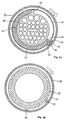
- a locking projection 52 is formed on the peripheral surface of the female housing 20 rearwardly from the spring accommodation grooves 41 and circumferentially opposing the spring seat 42 as shown in Fig. 4B.
- the side surfaces 52A of the locking projection 52 converge together.
- the locking projection 52 is tapered.
- a locking arm 54 forms a portion of the fixing ring 30. As shown in Fig. 1, front and rear slits are formed in the fixing ring 30 to define the locking arm 54.
- the locking arm 54 radially overlaps the rearward spring accommodation groove 41 and (when aligned) the locking projection 52. As shown in Fig. 4B, the locking arm 54 extends clockwise and is cantilevered so that the front (free) end is displaceable radially outwardly when the locking arm 54 is elastically deformed.
- a tapered projection 55 with converging side surfaces is formed at the front end of the inner surface of the locking arm 54 and extends across the whole width of the locking arm 54.
- the rearward (relative to the front and rear ends of the housing 20) half of the projection 55 abuts front side (relative to a clockwise rotational direction) of the locking projection 52.
- the forward half of the projection 55 in its widthwise direction fits in the engagement cavity 49 formed on the connection portion 48 of the fixing ring 30.
- the male terminal metal fittings are accommodated in the male housing 10 and are locked by the retainers 14.
- the male housing 10 is installed on an installing hole 17 of a panel 16 in preparation for engagement with the female housing 20.
- the female terminal metal fittings are accommodated in the female housing 20 and locked by the retainers 22.
- the fixing ring 30 is installed on the female housing 20 and is temporarily held at the predetermined position thereof, as described above.
- the female housing 20 is pressed into the male housing 10.
- the female housing 20 is fitted in the hood part 12, with the cavities 21 thereof aligned with the cavities 13 of the male housing 10.
- the follower pin 38 of the fixing ring 30 penetrates into the start portion 36A of the cam groove 36.
- the fixing ring 30 is rotated clockwise (as indicated by the arrow of Fig. 4).
- the follower pin 38 proceeds from the first linear portion 36B of the cam groove 36 to the inclined portion 36C thereof. Owing to the camming action of the follower pin 38 in the inclined portion 36C, the housings 10 and 20 are drawn toward each other.
- the housings 10 and 20 Due to the camming action of the follower pin 38 in the cam groove 36, the housings 10 and 20 gradually approach the fully engaged position under a comparatively small applied rotational force. However, when the engagement operation approaches its final stage, the male terminal metal fittings of the male housing 10 and the female terminal metal fittings of the female housing 20 are deeply interconnected which increases resistance to further engagement. Thus, there is a possibility that an operator may stop rotating the fixing ring 30 before the housings 10 and 20 are fully engaged.
- the coil springs 50 are unloaded and cause the loading ring 44 to rotate in the opposite direction. Therefore, when the housings 10 and 20 are fully engaged, the spring force of the coil springs 50 no longer acts to separate the housings 10 and 20 from each other. However, the coil springs 50 are not disabled and can be reused.
- the locking projection 52 has a semi-locking construction. That is, the locking arm 54 can ride across the locking projection 52 in both directions. Thus, when the fixing ring 30 is rotated in the counterclockwise direction at a force higher than a predetermined force, the fixing ring 30 escapes the detent, and then the fixing ring 30 can continue to be rotated to separate the housings 10 and 20.
Landscapes
- Details Of Connecting Devices For Male And Female Coupling (AREA)
Abstract
Description
Claims (4)
- An electrical connector having first (20) and second (10) matable connector housings with circular cross-sections, and having a fixing ring (30) which is rotatably mounted at an outer circumference of the first connector housing, in use, the fixing ring being engaged with the second connector housing to form a screw-action cam mechanism which draws the connector housings into mating engagement when the fixing ring is rotated in a first rotational direction relative to the connector housings,characterised in that the connector further has a detent for detaining the fixing ring at a predetermined position corresponding to full mating engagement of the connector housings, and a return spring (50) which applies a return bias to the fixing ring in a second rotational direction opposite to said first rotational direction as the fixing ring is rotated in the first rotational direction.
- A connector according to claim 1, wherein the return spring is a coil spring which is accommodated in a circumferential groove (41) formed in the first connector housing inwardly of the fixing ring, and there is provided a loading member (45) which is operably connectable to the fixing ring and which projects into the circumferential groove, so that when the fixing ring is rotated in the first rotational direction the loading member travels around the circumferential groove to load the coil spring and generate the return bias.
- A connector according to claim 2, wherein the loading member projects inwardly from a loading ring (44) which is rotatably mounted between the fixing ring and the circumferential groove, the fixing ring having a resiliently deformable latching arm (54) which is engageable with a corresponding portion (48) of the loading ring to operably connect the loading member to the fixing ring,the detent being provided by the latching arm and a locking projection (52) formed on the first connector housing, whereby when the fixing ring reaches the predetermined position, to detain the fixing ring the latching arm engages the locking projection with a latching action which involves a deformation of the latching arm, the deformation also disengaging the latching arm from the corresponding portion of the loading ring to release the coil spring and remove the return bias.
- A connector according to claim 3, wherein the latching arm and locking projection are adapted so that when at least a predetermined force is applied to the fixing ring to rotate the fixing ring in the opposite rotational direction, the latching arm disengages from the locking projection.
Applications Claiming Priority (2)
| Application Number | Priority Date | Filing Date | Title |
|---|---|---|---|
| JP23036899A JP3496753B2 (en) | 1999-08-17 | 1999-08-17 | connector |
| JP23036899 | 1999-08-17 |
Publications (3)
| Publication Number | Publication Date |
|---|---|
| EP1077510A2 true EP1077510A2 (en) | 2001-02-21 |
| EP1077510A3 EP1077510A3 (en) | 2001-12-05 |
| EP1077510B1 EP1077510B1 (en) | 2003-11-05 |
Family
ID=16906772
Family Applications (1)
| Application Number | Title | Priority Date | Filing Date |
|---|---|---|---|
| EP00306799A Expired - Lifetime EP1077510B1 (en) | 1999-08-17 | 2000-08-09 | Electrical connector |
Country Status (4)
| Country | Link |
|---|---|
| US (1) | US6234819B1 (en) |
| EP (1) | EP1077510B1 (en) |
| JP (1) | JP3496753B2 (en) |
| DE (1) | DE60006328T2 (en) |
Cited By (5)
| Publication number | Priority date | Publication date | Assignee | Title |
|---|---|---|---|---|
| FR2860650A1 (en) * | 2003-10-07 | 2005-04-08 | Framatome Connectors Int | ELECTRICAL CONNECTOR PROVIDED WITH A QUICK DISCONNECT SYSTEM |
| EP2706622A3 (en) * | 2012-09-06 | 2014-10-01 | Hirose Electric Co., Ltd. | Electrical connector assembled component |
| CN105075028A (en) * | 2013-03-13 | 2015-11-18 | 矢崎总业株式会社 | Connector device |
| CN105122557A (en) * | 2013-04-08 | 2015-12-02 | 矢崎总业株式会社 | Connector device |
| WO2017041285A1 (en) * | 2015-09-11 | 2017-03-16 | 郑进宇 | Industrial plug for marine refrigeration container |
Families Citing this family (9)
| Publication number | Priority date | Publication date | Assignee | Title |
|---|---|---|---|---|
| KR20030034581A (en) * | 2001-10-26 | 2003-05-09 | 현대자동차주식회사 | Hybrid female connector |
| US7165987B2 (en) * | 2004-09-28 | 2007-01-23 | Frank Chin-Hwan Kim | Industrial connector assembly |
| DE102006018927B4 (en) * | 2005-04-25 | 2010-10-21 | Yazaki Corp. | Electrical connector |
| JP2007179860A (en) | 2005-12-27 | 2007-07-12 | Jst Mfg Co Ltd | connector |
| CN107871978A (en) * | 2017-06-28 | 2018-04-03 | 徐学铖 | A kind of electricity consumption with electroshock-proof function plugs together component |
| CN107871979A (en) * | 2017-06-28 | 2018-04-03 | 徐学铖 | A kind of modified electricity consumption plugs together component |
| CN107230890A (en) * | 2017-06-28 | 2017-10-03 | 陈柯 | A kind of sanding apparatus |
| CN107871992A (en) * | 2017-06-28 | 2018-04-03 | 徐学铖 | A kind of Novel electric plugs together component |
| CN107984348A (en) * | 2017-06-28 | 2018-05-04 | 贾军霞 | A kind of Novel grinding device |
Family Cites Families (8)
| Publication number | Priority date | Publication date | Assignee | Title |
|---|---|---|---|---|
| US3869186A (en) * | 1973-10-09 | 1975-03-04 | Trw Inc | Electrical connector with automatic thread locking mechanism |
| US4239315A (en) * | 1978-12-18 | 1980-12-16 | International Telephone And Telegraph Corporation | Electrical connector |
| US4322121A (en) * | 1979-02-06 | 1982-03-30 | Bunker Ramo Corporation | Screw-coupled electrical connectors |
| FR2456405A1 (en) * | 1979-05-08 | 1980-12-05 | Souriau & Cie | ELECTRICAL CONNECTOR WITH TOUCH LOCK INDICATOR |
| US4255008A (en) * | 1979-08-31 | 1981-03-10 | The Bendix Corporation | Electrical connector assembly having anti-decoupling device |
| US4641811A (en) * | 1984-08-02 | 1987-02-10 | Allied Corp. | Electrical connector having a molded anti-decoupling mechanism |
| JPH04132178A (en) | 1990-09-20 | 1992-05-06 | Hino Motors Ltd | Electrical connector |
| JP2910500B2 (en) * | 1993-04-19 | 1999-06-23 | 住友電装株式会社 | Electric vehicle charging connector |
-
1999
- 1999-08-17 JP JP23036899A patent/JP3496753B2/en not_active Expired - Fee Related
-
2000
- 2000-08-09 EP EP00306799A patent/EP1077510B1/en not_active Expired - Lifetime
- 2000-08-09 DE DE60006328T patent/DE60006328T2/en not_active Expired - Fee Related
- 2000-08-17 US US09/641,928 patent/US6234819B1/en not_active Expired - Fee Related
Cited By (9)
| Publication number | Priority date | Publication date | Assignee | Title |
|---|---|---|---|---|
| FR2860650A1 (en) * | 2003-10-07 | 2005-04-08 | Framatome Connectors Int | ELECTRICAL CONNECTOR PROVIDED WITH A QUICK DISCONNECT SYSTEM |
| US7335037B2 (en) | 2003-10-07 | 2008-02-26 | Fci | Electrical connector which is equipped with a rapid disconnection system |
| EP2706622A3 (en) * | 2012-09-06 | 2014-10-01 | Hirose Electric Co., Ltd. | Electrical connector assembled component |
| US9054452B2 (en) | 2012-09-06 | 2015-06-09 | Hirose Electric Co., Ltd. | Electrical connector assembled component |
| CN105075028A (en) * | 2013-03-13 | 2015-11-18 | 矢崎总业株式会社 | Connector device |
| CN105075028B (en) * | 2013-03-13 | 2017-03-15 | 矢崎总业株式会社 | Electrical connector |
| CN105122557A (en) * | 2013-04-08 | 2015-12-02 | 矢崎总业株式会社 | Connector device |
| CN105122557B (en) * | 2013-04-08 | 2017-02-22 | 矢崎总业株式会社 | Connector device |
| WO2017041285A1 (en) * | 2015-09-11 | 2017-03-16 | 郑进宇 | Industrial plug for marine refrigeration container |
Also Published As
| Publication number | Publication date |
|---|---|
| DE60006328T2 (en) | 2004-08-26 |
| JP2001057271A (en) | 2001-02-27 |
| EP1077510B1 (en) | 2003-11-05 |
| DE60006328D1 (en) | 2003-12-11 |
| EP1077510A3 (en) | 2001-12-05 |
| JP3496753B2 (en) | 2004-02-16 |
| US6234819B1 (en) | 2001-05-22 |
Similar Documents
| Publication | Publication Date | Title |
|---|---|---|
| EP1077510B1 (en) | Electrical connector | |
| EP0638965B1 (en) | Circular bulkhead connector assembly | |
| US6045404A (en) | Electrical connector having a terminal position assurance device | |
| US7520765B2 (en) | Connector and connector assembly of the movable member type | |
| US7641485B2 (en) | Lever-type connector and a connector assembly | |
| US8057245B2 (en) | Lever-type connector | |
| US6065991A (en) | Half-fitting prevention connector | |
| US7407397B2 (en) | Lever-type connector and connector assembly | |
| US20020132510A1 (en) | Connector fitting structure | |
| EP1075052A1 (en) | Lever-type electrical connector | |
| US7214078B2 (en) | Connector and connector assembly | |
| US10263367B2 (en) | Electrical connector with rotary connector position assurance device | |
| US5820400A (en) | Half-fitting preventing connector | |
| JPH07230850A (en) | Lever type connector | |
| US6171130B1 (en) | Half-fitting prevention connector | |
| US6863551B2 (en) | Connector, set of connectors and method of connecting a connector | |
| JP2000331747A (en) | connector | |
| EP1045482A2 (en) | Connector | |
| JP2001118636A (en) | connector | |
| JP3250208B2 (en) | Mounting structure of valve socket | |
| US6132262A (en) | Electrical connector with improved contact reliability | |
| EP1001494B1 (en) | Electrical connector with terminal insertion detection means | |
| JP2025010924A (en) | Lever Type Connector | |
| JP2002117936A (en) | connector | |
| JP2000173715A (en) | Electrical junction box |
Legal Events
| Date | Code | Title | Description |
|---|---|---|---|
| PUAI | Public reference made under article 153(3) epc to a published international application that has entered the european phase |
Free format text: ORIGINAL CODE: 0009012 |
|
| 17P | Request for examination filed |
Effective date: 20000828 |
|
| AK | Designated contracting states |
Kind code of ref document: A2 Designated state(s): AT BE CH CY DE DK ES FI FR GB GR IE IT LI LU MC NL PT SE Kind code of ref document: A2 Designated state(s): DE FR IT |
|
| AX | Request for extension of the european patent |
Free format text: AL;LT;LV;MK;RO;SI |
|
| PUAL | Search report despatched |
Free format text: ORIGINAL CODE: 0009013 |
|
| AK | Designated contracting states |
Kind code of ref document: A3 Designated state(s): AT BE CH CY DE DK ES FI FR GB GR IE IT LI LU MC NL PT SE |
|
| AX | Request for extension of the european patent |
Free format text: AL;LT;LV;MK;RO;SI |
|
| RIC1 | Information provided on ipc code assigned before grant |
Free format text: 7H 01R 13/622 A, 7H 01R 13/635 B, 7H 01R 13/627 B, 7H 01R 13/623 B |
|
| AKX | Designation fees paid |
Free format text: DE FR IT |
|
| 17Q | First examination report despatched |
Effective date: 20020821 |
|
| GRAH | Despatch of communication of intention to grant a patent |
Free format text: ORIGINAL CODE: EPIDOS IGRA |
|
| GRAS | Grant fee paid |
Free format text: ORIGINAL CODE: EPIDOSNIGR3 |
|
| GRAA | (expected) grant |
Free format text: ORIGINAL CODE: 0009210 |
|
| AK | Designated contracting states |
Kind code of ref document: B1 Designated state(s): DE FR IT |
|
| REF | Corresponds to: |
Ref document number: 60006328 Country of ref document: DE Date of ref document: 20031211 Kind code of ref document: P |
|
| REG | Reference to a national code |
Ref country code: IE Ref legal event code: FG4D |
|
| ET | Fr: translation filed | ||
| PLBE | No opposition filed within time limit |
Free format text: ORIGINAL CODE: 0009261 |
|
| STAA | Information on the status of an ep patent application or granted ep patent |
Free format text: STATUS: NO OPPOSITION FILED WITHIN TIME LIMIT |
|
| 26N | No opposition filed |
Effective date: 20040806 |
|
| REG | Reference to a national code |
Ref country code: IE Ref legal event code: MM4A |
|
| PGFP | Annual fee paid to national office [announced via postgrant information from national office to epo] |
Ref country code: DE Payment date: 20080821 Year of fee payment: 9 |
|
| PGFP | Annual fee paid to national office [announced via postgrant information from national office to epo] |
Ref country code: FR Payment date: 20080818 Year of fee payment: 9 Ref country code: IT Payment date: 20080828 Year of fee payment: 9 |
|
| REG | Reference to a national code |
Ref country code: FR Ref legal event code: ST Effective date: 20100430 |
|
| PG25 | Lapsed in a contracting state [announced via postgrant information from national office to epo] |
Ref country code: DE Free format text: LAPSE BECAUSE OF NON-PAYMENT OF DUE FEES Effective date: 20100302 Ref country code: FR Free format text: LAPSE BECAUSE OF NON-PAYMENT OF DUE FEES Effective date: 20090831 |
|
| PG25 | Lapsed in a contracting state [announced via postgrant information from national office to epo] |
Ref country code: IT Free format text: LAPSE BECAUSE OF NON-PAYMENT OF DUE FEES Effective date: 20090809 |