EP1077488A2 - Thermally efficient motor controller assembly - Google Patents
Thermally efficient motor controller assembly Download PDFInfo
- Publication number
- EP1077488A2 EP1077488A2 EP00306990A EP00306990A EP1077488A2 EP 1077488 A2 EP1077488 A2 EP 1077488A2 EP 00306990 A EP00306990 A EP 00306990A EP 00306990 A EP00306990 A EP 00306990A EP 1077488 A2 EP1077488 A2 EP 1077488A2
- Authority
- EP
- European Patent Office
- Prior art keywords
- semiconductor switch
- assembly
- line
- support plate
- pair
- Prior art date
- Legal status (The legal status is an assumption and is not a legal conclusion. Google has not performed a legal analysis and makes no representation as to the accuracy of the status listed.)
- Withdrawn
Links
- 238000001816 cooling Methods 0.000 claims description 50
- 239000004065 semiconductor Substances 0.000 claims description 29
- 125000006850 spacer group Chemical group 0.000 claims description 13
- 239000007788 liquid Substances 0.000 claims description 4
- 229920001296 polysiloxane Polymers 0.000 abstract description 4
- 229910000838 Al alloy Inorganic materials 0.000 description 9
- 230000000712 assembly Effects 0.000 description 7
- 238000000429 assembly Methods 0.000 description 7
- 239000007858 starting material Substances 0.000 description 3
- 230000000694 effects Effects 0.000 description 2
- 229910052751 metal Inorganic materials 0.000 description 2
- 239000002184 metal Substances 0.000 description 2
- RYGMFSIKBFXOCR-UHFFFAOYSA-N Copper Chemical compound [Cu] RYGMFSIKBFXOCR-UHFFFAOYSA-N 0.000 description 1
- 229910045601 alloy Inorganic materials 0.000 description 1
- 239000000956 alloy Substances 0.000 description 1
- 229910052782 aluminium Inorganic materials 0.000 description 1
- XAGFODPZIPBFFR-UHFFFAOYSA-N aluminium Chemical compound [Al] XAGFODPZIPBFFR-UHFFFAOYSA-N 0.000 description 1
- 239000004020 conductor Substances 0.000 description 1
- 229910052802 copper Inorganic materials 0.000 description 1
- 239000010949 copper Substances 0.000 description 1
- 230000006698 induction Effects 0.000 description 1
- 239000000463 material Substances 0.000 description 1
- 238000000034 method Methods 0.000 description 1
- 238000013021 overheating Methods 0.000 description 1
- 230000001012 protector Effects 0.000 description 1
- 239000007787 solid Substances 0.000 description 1
Images


Classifications
-
- H—ELECTRICITY
- H05—ELECTRIC TECHNIQUES NOT OTHERWISE PROVIDED FOR
- H05K—PRINTED CIRCUITS; CASINGS OR CONSTRUCTIONAL DETAILS OF ELECTRIC APPARATUS; MANUFACTURE OF ASSEMBLAGES OF ELECTRICAL COMPONENTS
- H05K7/00—Constructional details common to different types of electric apparatus
- H05K7/20—Modifications to facilitate cooling, ventilating, or heating
- H05K7/2089—Modifications to facilitate cooling, ventilating, or heating for power electronics, e.g. for inverters for controlling motor
- H05K7/20909—Forced ventilation, e.g. on heat dissipaters coupled to components
Definitions
- This invention relates to motor controllers, and, more particularly, to thermally efficient motor controller assemblies.
- U.S. Patent No. 5,341,080 entitled Apparatus and Three Phase Induction Motor Starting and Stopping Control Method describes starters and contactors used to efficiently start and stop industrial rated electric motors.
- a more recent example of a motor controller unit is found in U.S. Patent No. 5,760,556 entitled Motor Controller and Protector Unit.
- solid state switches such as silicone controlled rectifiers (SCR), for example, are often employed to controllably switch the motor current to provide smooth motor starting and stopping function. Since the SCR's become heated upon current transfer therethrough, heat sinks in the form of large metal blocks of copper, aluminum and their alloys are required to protect the SCR's from overheating. The SCR's are usually spaced apart from the other motor controller components to facilitate cooling. Electrical connection between the SCR's and the other motor controller components is made by means of electrically-insulated thick metal cables, one for each phase of the associated electrical distribution system.
- U.S. Patent Application Serial No. 08/904,293 entitled Compact Electrical Equipment Enclosure describes an equipment enclosure that is open at the rear thereof to provide an air flow, so called “chimney effect.”
- the SCR's connecting with the motor controller are arranged apart from the other motor controller electric components within the air flow path to promote thermal cooling effects.
- the placement of the SCR's apart from the other electrical components increases the size of the equipment enclosure to some extent. This size limitation is critical when other devices such as circuit breakers and contactors are interconnected as described in U.S. Patent No. 5,657,193 entitled Electronic Control Module for Motor Controller Units.
- an arrangement for connection between motor controller electronic components and SCR's contained within the controller circuit is presented with the line and load straps being arranged on the bottom surface of the motor controller compartment at opposite ends thereof.
- the SCR's are positioned under the compartment on an elongated heat-sink support plate.
- Intermediate block connectors interconnect SCR's with the controller line and load straps.
- a highly-efficient cooling fan is arranged on the elongated heat-sink support plate to rapidly control the temperature of the SCR's during motor start and stop function.
- a thermistor control switch can be employed for turning the switching the cooling fan in accordance with the SCR cooling requirements.
- the SCR's do not have to be separate from the other components or employ special motor controller equipment enclosure designs, as in the prior art.
- This arrangement provides efficient means for cooling the SCR's with a minimum space and cost requirement while facilitating electrical connection between the motor controller components and the SCR's as well as between the SCR's and the electrical distribution system connectors.
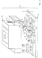
- Motor controller assembly 10 is generally shown at 10 such as described in the aforementioned U.S. Patent No. 5,341,080.
- Motor controller assembly 10 includes a motor controller unit 14, a motor starter 11, a display 12 and control buttons 13 positioned on a heat sink plate 18.
- Line straps 15 and load straps 16 are arranged outboard the unit on the opposite ends of the heat sink plate.
- Heat sink plate 18 is fabricated from, e.g., an aluminum alloy for good thermal transport, or other suitable material.
- An SCR assembly 17 is arranged under the line and load straps in the manner to be described below and a cooling fan 19 assembly, similar to that described within U.S. Patent No.
- the motor controller assembly 10 is shown in Figure 2 prior to attaching the motor starter 11 and prior to attaching the SCR assembly 17 to the heat sink plate 18.
- the heat sink plate 18 with the cooler fan 19 attached thereon, is fastened to the heat sink plate through holes 35, 37 by screws 36 for attaching the SCR assembly prior to attaching the motor controller to the SCR assembly.
- the cooling fan assembly 19 includes a central aperture 33 for egress of the heated air away from the heat sink plate 18 by a high speed fan 34.
- SCR assembly 17 includes heat sink plate thru-holes 30 on opposite ends for attaching the assembly to the heat sink plate 18 by bolts 32.
- Bridge block thru-holes 31 at the middle thereof provide for attachment of a U-shaped bridge block 22 by bolts 28.
- the U-shaped bridge block 22 defines a pair of opposing sidepieces 23, 24 joined by a top bright 25 and is also fabricated from, e.g., an aluminum alloy.
- SCR thru-holes 27 through the center portion of the top bight 25 receive the bolts 28 before threadingly engaging the bolts 28 within the bridge block thru-holes 31 in the top part of the SCR.
- Elongated thru-holes 26 extending through the sidepieces 23, 24 are aligned under a pair of stand-off spacers 20, each having an elongated thru-hole 21.
- the line straps 15 on the line side of the controller 11 and the load straps (not shown) on the load side thereof are attached to the U-shaped bridge block 22 by spacers 20 via spacer thru-holes 21, thru-holes 27 and elongated bolts 9 to complete the assembly 20 via spacer thru-holes 21, thru-holes 27 and elongated bolts 9 to complete the assembly 10.
- a thermistor 41 can be arranged on the SCR 29 and connected with a control circuit over conductor 42 to turn the cooling fan 34 ON and OFF in accordance with the temperature range programmed within the control circuit in the manner described within U.S. Patent No. 3,693,047 entitled, Apparatus for Protecting Electrical Devices.
- the SCR assembly 17 is shown in Figure 3 prior to attaching an electric contactor 38 shown in phantom.
- the assembly 17 with the a set of three such line side SCR assemblies 17A, for connecting with each pole on the line end and a set of three such load side SCR assemblies 17B for connecting with each pole on the load end of the contactor 38.
- Corresponding U-shaped bridge blocks 22 are attached to each of the line and load end SCR assemblies 17A, 17B, as indicated.
- the spacers 20, shown in phantom are configured for the spacing requirements between the line straps 39 on the contactor 38 and the line end U-shaped bridge blocks 22 to facilitate connection therewith by bolts 40, shown in phantom.
- the spacers are also fabricated from, e.g., an aluminum alloy.
- the line and load end SCR assemblies 17A, 17B along with the cooling fan assembly 19 on the heat sink plate 18 are shown prior to connection with a contactor 38.
- An SCR assembly has herein been disclosed for use with electrical devices such as motor controllers, contactors and the like for providing optimum cooling to the SCR's both during short term high current operating conditions as well as under long time continuous operation during quiescent current operating conditions.
Landscapes
- Engineering & Computer Science (AREA)
- Microelectronics & Electronic Packaging (AREA)
- Physics & Mathematics (AREA)
- Thermal Sciences (AREA)
- Cooling Or The Like Of Semiconductors Or Solid State Devices (AREA)
- Rectifiers (AREA)
Abstract
Description
a U-shaped block (22) defining a pair of sidepieces (23, 24) joined by a bright (25), said bight (25) including a first pair of apertures (27) arranged superjacent a corresponding second pair of apertures (31) within said semiconductor switches (29).
a third aperture (26) within said first sidepiece (23) and a fourth aperture (26) within said second sidepiece (24), said third and fourth apertures (26) being arranged subjacent straps (15, 16) connecting with said associated electrical device (11).
a pair of apertured spacers (20, 21) arranged between said associated electrical device (11) and said first and second sidepieces (23, 24) for connecting said straps (15, 16) with said first and second sidepieces (23, 24).
providing said line and load straps (15, 16) on a bottom of said contactor and connecting said line and load straps (15, 16) with a semiconductor switch assembly (17).
and
a U-shaped block (22) defining a pair of sidepieces (23, 24) joined by a bight (25), said bight (25) including a first pair of apertures (27) arranged superjacent a corresponding second pair of apertures (31) within said semiconductor switch devices (29).
a third aperture (26) within said first sidepiece (23) and a forth aperture (26) within said second sidepiece (24), said third and fourth apertures being arranged subjacent line and load straps (15, 16).
a pair of apertured spacers (20, 21) arranged between said line and load straps (15, 16) and said first and second sidepieces (23, 24) for connecting said line and load straps (15, 16) with said first and second sidepieces (23, 24).
Claims (10)
- A cooling assembly for semiconductor switches comprising:a heat sink support plate (18);a plurality of semiconductor switch devices (29) mounted on said support plate (18);a cooling assembly (19) arranged on said support plate (18) for removing heat away from said heat sink support plate (18) and said semiconductor switch devices (29); anda connector (22) on said semiconductor switch devices (29) for electrically connecting said semiconductor switch devices (29) with an electrical device (11).
- The cooling assembly of Claim 1 wherein said connector comprises:
a U-shaped block (22) defining a pair of sidepieces (23, 24) joined by a bright (25), said bight (25) including a first pair of apertures (27) arranged superjacent a corresponding second pair of apertures (31) within said semiconductor switches (29). - The cooling assembly of Claim 2 including:
a third aperture (26) within said first sidepiece (23) and a fourth aperture (26) within said second sidepiece (24), said third and fourth apertures (26) being arranged subjacent straps (15, 16) connecting with said associated electrical device (11). - The cooling assembly of Claim 3 including:
a pair of apertured spacers (20, 21) arranged between said associated electrical device (11) and said first and second sidepieces (23, 24) for connecting said straps (15, 16) with said first and second sidepieces (23, 24). - The cooling assembly of Claim 1 wherein said cooling assembly (19) comprises an air cooling device or a liquid cooling device.
- An electrical contactor assembly of the type having line and load straps (15, 16) at opposite ends for connection with an electrical distribution circuit, wherein the improvement comprises:
providing said line and load straps (15, 16) on a bottom of said contactor and connecting said line and load straps (15, 16) with a semiconductor switch assembly (17). - The electrical contactor of Claim 6 wherein said semiconductor switch assembly comprises:a heat sink support plate (18);a plurality of semiconductor switch devices (29) mounted on said support plate (18);a cooling assembly (19) arranged on said support plate (18) for removing heat away from said heat sink support plate (18) and said semiconductor switch devices (29);
anda connector (22) said semiconductor switch devices (29) for electrically connecting said semiconductor switch devices (29) with said line and load straps (15, 16). - The electrical contactor of Claim 7 wherein said connector comprises:
a U-shaped block (22) defining a pair of sidepieces (23, 24) joined by a bight (25), said bight (25) including a first pair of apertures (27) arranged superjacent a corresponding second pair of apertures (31) within said semiconductor switch devices (29). - The electrical contactor of Claim 8 including:
a third aperture (26) within said first sidepiece (23) and a forth aperture (26) within said second sidepiece (24), said third and fourth apertures being arranged subjacent line and load straps (15, 16). - The electrical contactor of Claim 9 including:
a pair of apertured spacers (20, 21) arranged between said line and load straps (15, 16) and said first and second sidepieces (23, 24) for connecting said line and load straps (15, 16) with said first and second sidepieces (23, 24).
Applications Claiming Priority (2)
| Application Number | Priority Date | Filing Date | Title |
|---|---|---|---|
| US09/374,786 US6249435B1 (en) | 1999-08-16 | 1999-08-16 | Thermally efficient motor controller assembly |
| US374786 | 1999-08-16 |
Publications (2)
| Publication Number | Publication Date |
|---|---|
| EP1077488A2 true EP1077488A2 (en) | 2001-02-21 |
| EP1077488A3 EP1077488A3 (en) | 2001-05-23 |
Family
ID=23478194
Family Applications (1)
| Application Number | Title | Priority Date | Filing Date |
|---|---|---|---|
| EP00306990A Withdrawn EP1077488A3 (en) | 1999-08-16 | 2000-08-16 | Thermally efficient motor controller assembly |
Country Status (2)
| Country | Link |
|---|---|
| US (1) | US6249435B1 (en) |
| EP (1) | EP1077488A3 (en) |
Cited By (2)
| Publication number | Priority date | Publication date | Assignee | Title |
|---|---|---|---|---|
| EP1511165A3 (en) * | 2003-08-29 | 2007-10-10 | Rockwell Automation Technologies, Inc. | Multiphase reduced voltage starter with bypass relays, interphase electrical isolation and shared thermal mass |
| CN114665445A (en) * | 2022-05-20 | 2022-06-24 | 上海华建电力设备股份有限公司 | Motor monitoring device |
Families Citing this family (38)
| Publication number | Priority date | Publication date | Assignee | Title |
|---|---|---|---|---|
| US8540493B2 (en) | 2003-12-08 | 2013-09-24 | Sta-Rite Industries, Llc | Pump control system and method |
| US8019479B2 (en) | 2004-08-26 | 2011-09-13 | Pentair Water Pool And Spa, Inc. | Control algorithm of variable speed pumping system |
| US7874808B2 (en) | 2004-08-26 | 2011-01-25 | Pentair Water Pool And Spa, Inc. | Variable speed pumping system and method |
| US8602745B2 (en) | 2004-08-26 | 2013-12-10 | Pentair Water Pool And Spa, Inc. | Anti-entrapment and anti-dead head function |
| US7686589B2 (en) | 2004-08-26 | 2010-03-30 | Pentair Water Pool And Spa, Inc. | Pumping system with power optimization |
| US8480373B2 (en) | 2004-08-26 | 2013-07-09 | Pentair Water Pool And Spa, Inc. | Filter loading |
| US7845913B2 (en) | 2004-08-26 | 2010-12-07 | Pentair Water Pool And Spa, Inc. | Flow control |
| US7854597B2 (en) | 2004-08-26 | 2010-12-21 | Pentair Water Pool And Spa, Inc. | Pumping system with two way communication |
| US8469675B2 (en) | 2004-08-26 | 2013-06-25 | Pentair Water Pool And Spa, Inc. | Priming protection |
| USD560608S1 (en) * | 2005-11-21 | 2008-01-29 | Siemens Aktiengesellschaft | Motor starter |
| CN101513150B (en) * | 2006-09-04 | 2011-08-10 | 株式会社安川电机 | Motor control device |
| DE112007002035T5 (en) * | 2006-09-06 | 2009-07-30 | Kabushiki Kaisha Yaskawa Denki, Kitakyushu | Motor controller |
| DE102007003329B3 (en) * | 2007-01-17 | 2008-04-10 | Siemens Ag | Cooling arrangement for arranged in a housing electrical components of a soft starter, and soft starter |
| USD567178S1 (en) * | 2007-01-18 | 2008-04-22 | Siemens Aktiengesellschaft | Semiconductor based motor control device |
| BRMU8701723U2 (en) * | 2007-11-01 | 2009-06-23 | Weg Automacao S A | Constructive arrangement in static starter |
| TWD128647S1 (en) * | 2008-04-25 | 2009-05-11 | 崇貿科技股份有限公司 | Brushless DC Motor Controller |
| AU2009302593B2 (en) | 2008-10-06 | 2015-05-28 | Danfoss Low Power Drives | Method of operating a safety vacuum release system |
| US8564233B2 (en) | 2009-06-09 | 2013-10-22 | Sta-Rite Industries, Llc | Safety system and method for pump and motor |
| US8436559B2 (en) * | 2009-06-09 | 2013-05-07 | Sta-Rite Industries, Llc | System and method for motor drive control pad and drive terminals |
| US9556874B2 (en) | 2009-06-09 | 2017-01-31 | Pentair Flow Technologies, Llc | Method of controlling a pump and motor |
| US7929305B1 (en) | 2009-07-16 | 2011-04-19 | Hamilton Sundstrand Corporation | Power electronics cooling system with flow orifice control |
| USD683698S1 (en) * | 2010-02-24 | 2013-06-04 | Abb Oy | Cabinet for a frequency converter |
| USD685733S1 (en) * | 2010-02-24 | 2013-07-09 | Abb Oy | Cabinet for a frequency converter |
| USD647846S1 (en) * | 2010-03-23 | 2011-11-01 | Abb Ab | Motor starter |
| USD647844S1 (en) * | 2010-03-23 | 2011-11-01 | Abb Ab | Motor starter |
| USD647845S1 (en) * | 2010-03-23 | 2011-11-01 | Abb Ab | Motor starter |
| US8957316B2 (en) | 2010-09-10 | 2015-02-17 | Honeywell International Inc. | Electrical component assembly for thermal transfer |
| USD654022S1 (en) * | 2010-09-13 | 2012-02-14 | Vacon Oyj | Frequency converter |
| US9243413B2 (en) | 2010-12-08 | 2016-01-26 | Pentair Water Pool And Spa, Inc. | Discharge vacuum relief valve for safety vacuum release system |
| BR112014010665A2 (en) | 2011-11-01 | 2017-12-05 | Pentair Water Pool & Spa Inc | flow blocking system and process |
| US9885360B2 (en) | 2012-10-25 | 2018-02-06 | Pentair Flow Technologies, Llc | Battery backup sump pump systems and methods |
| EP3954352B1 (en) | 2013-03-15 | 2024-08-21 | Hayward Industries, Inc. | Modular pool/spa control system |
| US20150048690A1 (en) * | 2013-08-15 | 2015-02-19 | Solcon Industries Ltd. | Medium voltage power controller |
| USD845253S1 (en) * | 2014-07-14 | 2019-04-09 | Atlas Copco Airpower, Naamloze Vennootschap | Casing for equipment for control of electric power |
| USD850389S1 (en) * | 2015-01-30 | 2019-06-04 | Energybox Ltd | Control device |
| US10363197B2 (en) | 2016-01-22 | 2019-07-30 | Hayward Industries, Inc. | Systems and methods for providing network connectivity and remote monitoring, optimization, and control of pool/spa equipment |
| US11720085B2 (en) | 2016-01-22 | 2023-08-08 | Hayward Industries, Inc. | Systems and methods for providing network connectivity and remote monitoring, optimization, and control of pool/spa equipment |
| US9918406B2 (en) * | 2016-07-12 | 2018-03-13 | Hamilton Sundstrand Corporation | Mounting arrangements for electrical contactors |
Family Cites Families (17)
| Publication number | Priority date | Publication date | Assignee | Title |
|---|---|---|---|---|
| US3693047A (en) | 1971-09-28 | 1972-09-19 | Gen Electric | Apparatus for protecting electrical devices |
| US4336568A (en) * | 1980-07-24 | 1982-06-22 | Westinghouse Electric Corp. | Packaged solid state power controller with separable mounting for a power switching device, and method of assembly |
| US4618817A (en) * | 1985-09-12 | 1986-10-21 | Wolf Engineering Corporation | Multiple phase switching circuit and heat sink structure |
| US4769557A (en) * | 1987-02-19 | 1988-09-06 | Allen-Bradley Company, Inc. | Modular electric load controller |
| US4895005A (en) * | 1988-12-29 | 1990-01-23 | York International Corporation | Motor terminal box mounted solid state starter |
| ES2047446B1 (en) | 1992-05-04 | 1996-10-16 | Power Controls Iberica S A | APPARATUS AND METHOD OF CONTROL OF START AND STOP OF THREE-PHASE ASYNCHRONOUS MOTORS. |
| US5610493A (en) * | 1995-04-12 | 1997-03-11 | Allen-Bradley Company, Inc. | Terminal configuration for a motor controller |
| US5699609A (en) * | 1995-04-12 | 1997-12-23 | Allen-Bradley Company, Inc. | Method of making power substrate assembly |
| US5760556A (en) | 1996-01-26 | 1998-06-02 | General Electric Company | Motor controller and protector unit |
| US5657193A (en) | 1996-01-26 | 1997-08-12 | General Electric Company | Electronic control module for motor controller units |
| JPH09289282A (en) * | 1996-04-19 | 1997-11-04 | Omron Corp | Non-contact relay for three-phase load |
| US5690468A (en) | 1996-06-19 | 1997-11-25 | Hong; Chen Fu-In | Fan assembly for an integrated circuit |
| US5742478A (en) * | 1996-09-25 | 1998-04-21 | Wu; Chih-Hsien | Radiating structure of a power converter |
| JP3416450B2 (en) * | 1997-03-21 | 2003-06-16 | 三菱電機株式会社 | Power transistor module mounting structure |
| US6104602A (en) * | 1997-07-31 | 2000-08-15 | General Electric Company | Compact electrical equipment enclosure |
| DE19813639A1 (en) * | 1998-03-27 | 1999-11-25 | Danfoss As | Power module for a converter |
| US6087800A (en) * | 1999-03-12 | 2000-07-11 | Eaton Corporation | Integrated soft starter for electric motor |
-
1999
- 1999-08-16 US US09/374,786 patent/US6249435B1/en not_active Expired - Fee Related
-
2000
- 2000-08-16 EP EP00306990A patent/EP1077488A3/en not_active Withdrawn
Cited By (2)
| Publication number | Priority date | Publication date | Assignee | Title |
|---|---|---|---|---|
| EP1511165A3 (en) * | 2003-08-29 | 2007-10-10 | Rockwell Automation Technologies, Inc. | Multiphase reduced voltage starter with bypass relays, interphase electrical isolation and shared thermal mass |
| CN114665445A (en) * | 2022-05-20 | 2022-06-24 | 上海华建电力设备股份有限公司 | Motor monitoring device |
Also Published As
| Publication number | Publication date |
|---|---|
| US6249435B1 (en) | 2001-06-19 |
| EP1077488A3 (en) | 2001-05-23 |
Similar Documents
| Publication | Publication Date | Title |
|---|---|---|
| US6249435B1 (en) | Thermally efficient motor controller assembly | |
| KR100996791B1 (en) | Main Circuit Terminal Assembly of Vacuum Circuit Breaker | |
| US6104602A (en) | Compact electrical equipment enclosure | |
| EP1245455B1 (en) | Electric power distributor for use in motor vehicle | |
| US6856503B2 (en) | Control device | |
| US6556404B2 (en) | Self powered cooling fan and method | |
| US7149064B2 (en) | Multiphase reduced voltage starter with bypass relays, interphase electrical isolation and shared thermal mass | |
| US6108206A (en) | Semiconductor thermal protection arrangement | |
| CN111418142B (en) | Board-level motor control system with integrated protection and control components | |
| US20210336426A1 (en) | Heat sink for power supply panel | |
| CN103262196B (en) | Electrical system and its circuit protection module and electrical switching device | |
| US9147541B2 (en) | Circuit breaker comprising ventilation channels for efficient heat dissipation | |
| EP2653022B1 (en) | Electrical system and matrix assembly therefor | |
| US9799462B2 (en) | Switching device with a heat extraction apparatus | |
| WO2024175251A1 (en) | Thermal management of active discharge function in automotive inverters | |
| CA2656201C (en) | Electronic module configured for failure containment and system including same | |
| EP1758136B1 (en) | Electrical switching apparatus and heat sink therefor | |
| KR20200118701A (en) | Temperature rising preventing apparatus for air circuit breaker | |
| JP7689280B2 (en) | Breaker | |
| EP3066906B1 (en) | Power distribution assembly and header assembly therefor | |
| JPH09308077A (en) | Circuit protection device against overcurrent | |
| JPH10136558A (en) | Current limiter using ptc device |
Legal Events
| Date | Code | Title | Description |
|---|---|---|---|
| PUAI | Public reference made under article 153(3) epc to a published international application that has entered the european phase |
Free format text: ORIGINAL CODE: 0009012 |
|
| AK | Designated contracting states |
Kind code of ref document: A2 Designated state(s): AT BE CH CY DE DK ES FI FR GB GR IE IT LI LU MC NL PT SE |
|
| AX | Request for extension of the european patent |
Free format text: AL;LT;LV;MK;RO;SI |
|
| PUAL | Search report despatched |
Free format text: ORIGINAL CODE: 0009013 |
|
| AK | Designated contracting states |
Kind code of ref document: A3 Designated state(s): AT BE CH CY DE DK ES FI FR GB GR IE IT LI LU MC NL PT SE |
|
| AX | Request for extension of the european patent |
Free format text: AL;LT;LV;MK;RO;SI |
|
| RIC1 | Information provided on ipc code assigned before grant |
Free format text: 7H 01L 23/40 A, 7H 01L 23/48 B, 7H 02H 7/08 B, 7H 05K 7/20 B |
|
| 17P | Request for examination filed |
Effective date: 20011123 |
|
| AKX | Designation fees paid |
Free format text: AT BE CH CY DE DK ES FI FR GB GR IE IT LI LU MC NL PT SE |
|
| STAA | Information on the status of an ep patent application or granted ep patent |
Free format text: STATUS: THE APPLICATION IS DEEMED TO BE WITHDRAWN |
|
| 18D | Application deemed to be withdrawn |
Effective date: 20060503 |