EP1077458B1 - Circuit interrupter with non-symmetrical terminal collar - Google Patents
Circuit interrupter with non-symmetrical terminal collar Download PDFInfo
- Publication number
- EP1077458B1 EP1077458B1 EP00116257A EP00116257A EP1077458B1 EP 1077458 B1 EP1077458 B1 EP 1077458B1 EP 00116257 A EP00116257 A EP 00116257A EP 00116257 A EP00116257 A EP 00116257A EP 1077458 B1 EP1077458 B1 EP 1077458B1
- Authority
- EP
- European Patent Office
- Prior art keywords
- terminal
- housing
- operating mechanism
- collar
- disposed
- Prior art date
- Legal status (The legal status is an assumption and is not a legal conclusion. Google has not performed a legal analysis and makes no representation as to the accuracy of the status listed.)
- Expired - Lifetime
Links
- 230000007246 mechanism Effects 0.000 claims description 24
- 230000005405 multipole Effects 0.000 claims 5
- 239000004020 conductor Substances 0.000 description 9
- 230000009471 action Effects 0.000 description 8
- 229910000831 Steel Inorganic materials 0.000 description 5
- 239000010959 steel Substances 0.000 description 5
- 229910052782 aluminium Inorganic materials 0.000 description 4
- XAGFODPZIPBFFR-UHFFFAOYSA-N aluminium Chemical class [Al] XAGFODPZIPBFFR-UHFFFAOYSA-N 0.000 description 4
- 230000006835 compression Effects 0.000 description 4
- 238000007906 compression Methods 0.000 description 4
- 229910052751 metal Inorganic materials 0.000 description 4
- 239000002184 metal Substances 0.000 description 4
- 230000004044 response Effects 0.000 description 2
- 230000001419 dependent effect Effects 0.000 description 1
- 230000003467 diminishing effect Effects 0.000 description 1
- 238000010891 electric arc Methods 0.000 description 1
- 230000004907 flux Effects 0.000 description 1
- 230000000977 initiatory effect Effects 0.000 description 1
- 238000009413 insulation Methods 0.000 description 1
- 238000002955 isolation Methods 0.000 description 1
- 238000013021 overheating Methods 0.000 description 1
- 238000000926 separation method Methods 0.000 description 1
Images


Classifications
-
- H—ELECTRICITY
- H01—ELECTRIC ELEMENTS
- H01H—ELECTRIC SWITCHES; RELAYS; SELECTORS; EMERGENCY PROTECTIVE DEVICES
- H01H71/00—Details of the protective switches or relays covered by groups H01H73/00 - H01H83/00
- H01H71/08—Terminals; Connections
-
- H—ELECTRICITY
- H01—ELECTRIC ELEMENTS
- H01R—ELECTRICALLY-CONDUCTIVE CONNECTIONS; STRUCTURAL ASSOCIATIONS OF A PLURALITY OF MUTUALLY-INSULATED ELECTRICAL CONNECTING ELEMENTS; COUPLING DEVICES; CURRENT COLLECTORS
- H01R4/00—Electrically-conductive connections between two or more conductive members in direct contact, i.e. touching one another; Means for effecting or maintaining such contact; Electrically-conductive connections having two or more spaced connecting locations for conductors and using contact members penetrating insulation
- H01R4/28—Clamped connections, spring connections
- H01R4/30—Clamped connections, spring connections utilising a screw or nut clamping member
- H01R4/307—Clamped connections, spring connections utilising a screw or nut clamping member characterised by the thread of the screw or nut
-
- H—ELECTRICITY
- H01—ELECTRIC ELEMENTS
- H01H—ELECTRIC SWITCHES; RELAYS; SELECTORS; EMERGENCY PROTECTIVE DEVICES
- H01H1/00—Contacts
- H01H1/58—Electric connections to or between contacts; Terminals
- H01H1/5855—Electric connections to or between contacts; Terminals characterised by the use of a wire clamping screw or nut
- H01H2001/5861—Box connector with a collar or lug for clamping internal rail and external conductor together by a tightening screw
-
- H—ELECTRICITY
- H01—ELECTRIC ELEMENTS
- H01H—ELECTRIC SWITCHES; RELAYS; SELECTORS; EMERGENCY PROTECTIVE DEVICES
- H01H2300/00—Orthogonal indexing scheme relating to electric switches, relays, selectors or emergency protective devices covered by H01H
- H01H2300/042—Application rejection, i.e. preventing improper installation of parts
-
- H—ELECTRICITY
- H01—ELECTRIC ELEMENTS
- H01R—ELECTRICALLY-CONDUCTIVE CONNECTIONS; STRUCTURAL ASSOCIATIONS OF A PLURALITY OF MUTUALLY-INSULATED ELECTRICAL CONNECTING ELEMENTS; COUPLING DEVICES; CURRENT COLLECTORS
- H01R4/00—Electrically-conductive connections between two or more conductive members in direct contact, i.e. touching one another; Means for effecting or maintaining such contact; Electrically-conductive connections having two or more spaced connecting locations for conductors and using contact members penetrating insulation
- H01R4/28—Clamped connections, spring connections
- H01R4/30—Clamped connections, spring connections utilising a screw or nut clamping member
- H01R4/36—Conductive members located under tip of screw
Definitions
- the subject matter of this invention is related generally to molded case circuit breakers and more specifically to terminal collars for molded case circuit breakers.
- Molded case circuit breakers are well known in the art as exemplified by U.S. Patent 5,910,760 issued June 8, 1999 to Malingowski et al. , entitled “Circuit Breaker with Double Rate Spring” and assigned to the assignee of the present application.
- Molded case circuit breakers include a set of separable main contacts, one of which is usually fixed and one of which is movable for automatically opening upon the occurrence of an overload or short circuit electrical current in the network which the circuit breaker is provide to protect.
- the separable main contacts are opened as a result of the functioning of a latched operating mechanism, which is interconnectable by way of an operating handle to a region outside of the circuit breaker.
- the operating handle may be used to trip the circuit breaker manually or to reset and close the circuit breaker contacts once they have been opened automatically.
- the reset action is required because circuit breakers must be mechanically charged to be in a state to reopen immediately upon closure in the event that the fault which cause the tripping in the first place has not disappeared.
- Molded case circuit breakers have trip units, which are often removably insertable in the circuit breaker case.
- the trip unit in addition has at least two calibratable functions, one of which is generally identified as thermal tripping and the other of which is generally identified as magnetic tripping.
- the trip unit includes a rotatable trip bar, which when rotated will actuate a latchable tripping operation within the operating mechanism to automatically open the circuit breaker contacts.
- the rotatable trip bar is usually actuated in one of two ways. The first way is in response to what is called a magnetic tripping of the circuit breaker.
- a bi-metal element is heated by a heater element which conducts the electrical current flowing through the separable main contacts.
- a heater element which conducts the electrical current flowing through the separable main contacts.
- the bi-metal element flexes or moves it impinges upon the tripping bar causing it to flex and move correspondingly, until eventually a point is reached in which the tripping bar causes the circuit breaker to unlatch and trip automatically.
- Both the magnetic trip mechanism and the thermal trip mechanism usually require initial calibration.
- the electrical current flows through the circuit interrupter from the load by way of a terminal collar to the load terminal of the circuit breaker and from there into the trip unit where it flows through the previously mentioned heater which in turn is serially connected to the electron magnetic member of the magnetic trip device. From there it is interconnected by way of a flexible cable to one end of a moveable contact arm and from there to the main contact on the moveable contact arm.
- the contact arm When the contact arm is closed, it is closed upon a fixed contact which is supported usually on u-shaped conductor, which in turn is interconnected with a line terminal and there to the line terminal collar and finally to the electrical line.
- the circuit breaker usually has an arc chute for assisting in diminishing the electrical arc drawn between the separating contacts during the opening operation for extinguishing of the arc.
- the circuit breaker also has a slot motor arrangement, which is utilized to interact magnetically with the electrical current flowing in the opening contact arm to accelerate the opening of the contact arm magnetically.
- the operating mechanism usually consists of a series of levers and linkages, which are interconnected with the separable main moveable contact arm, the handle mechanism, and by way of a latch arrangement with the aforementioned trip bar. Description and operation of all of the above may be found in the previous mentioned, incorporated by reference '760 patent.
- Molded case circuit breakers usually have collars which interface the line and load terminals of the circuit breaker with electrical cables.
- a collar may be found in U.S. 5,206,789 issued April 27, 1993 to Barbry et al. , entitled "Terminal Assembly for a Circuit Breaker and Similar Apparatus" and assigned to the assignee of the present application.
- Other examples of such arrangements may be found in U.S. Patent 5,005,104 .
- these collars have been basically symmetrical in nature. That it is, the functions, equally well in a number of orientations.
- circuit interrupter device as set forth in claims 1, and a circuit interrupter device, as set forth in claim 3, are provided.
- Embodiments of the invention are described in the dependent claims.
- a circuit interrupter having a housing. There is an operating mechanism disposed within the housing. Also, separable contacts are disposed within the housing in cooperation with the operating mechanism for being opened by the operating mechanism, a terminal is interconnected with the separable contacts for providing an electrical conduction path from a region outside of the housing to the separable contacts.
- the terminal has a non-symmetrically shaped terminal collar connected thereto with a region of relatively smaller dimension relative to a region of relatively larger dimension, the closest uninsulated path between the non-symmetrically shaped terminal collar and the nearest external portion of the housing being from the region of relatively smaller dimension.
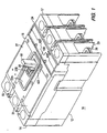
- a molded case circuit breaker or interrupter 10 having a main base 12 and primary cover 14. Attached to the primary cover 14 is a secondary cover 16. A handle 18 extends through a secondary escutcheon 22A in the secondary cover 16 and aligned primary escutcheon 22B in the primary cover 14. An operating mechanism 20 is interconnected with the handle 18 for opening and closing separable main contacts in a manner which will be described hereinafter.
- This circuit breaker has a line end 15 and load end 17.
- the circuit breaker or interrupter includes a removable trip unit 24. Removable trip unit 24 has an underlapping lip 24X, the purpose of which will be described hereinafter. There are also depicted a load terminal 26, a right side accessory region or pocket 27 and a left side accessory pocket or region 31.
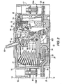
- Line terminal 36 is disposed to the left in Figure 2 , for example, at the line end 15 of the circuit interrupter in a terminal cave or pocket 29.
- a load terminal 26 is disposed to the right in Figure 2 , for example, in a load terminal cave or pocket 29.
- To the left on the line terminal 36 is disposed a line terminal collar 38 which will be described in more detail hereinafter, and to the right is provided a load terminal jumper-to-movable contact arm conductor 802.
- a flexible conductor 39 Connected to conductor 802 is a flexible conductor 39, which is interconnected with movable contact arm 32 as shown schematically.
- the load terminal jumper or frame conductor 802 is interconnected at its other end with a bi-metal heater 180, which in turn is interconnected at its other end with the terminal 26. Consequently, when the circuit interrupter separable main contacts 28 and 30 are closed upon each other, there is a complete circuit through the circuit interrupter from right to left starting with line conductor 26 through bi-metal heater 180, through load terminal jumper or frame conductor 802, through flexible conductor 39, through the movable contact arm 32, through contact 28 to contact 30 and from there through the fixed contact support or u-shaped member 34 to line terminal 36.
- the operating mechanism includes a cradle 52, which is pivoted on one end at a cradle fixed pivoted pin 54 by way of an opening 54A in the cradle for placement of the cradle fixed pivoted pin therein.
- the cradle includes a cradle-to-side accessory region side protrusion 55.
- an upper toggle link 46 and a lower toggle link 48 are joined pivotally by an upper and lower toggle link pin 50.
- There is provided a lower toggle link to movable contact arm main pivot assemble attachment pin 56 which is affixed to the movable contact arm 32 at an opening 56A.
- a cradle to upper toggle link pivot pin 58 by which the upper toggle link 46 is placed in physical contact with the cradle 52.
- a movable contact arm main pivot assembly 59 which movably, rotatably pivots on a pivot 60.
- a primary frame latch 62 which operates or rotates on a primary frame latch pivot 64.
- the primary frame latch 62 cooperates with a secondary frame latch 68, which rotates on a secondary frame latch pivot 70.
- the operating power for the tripping operating of the circuit breaker is provided by a charged main toggle coil spring 72.
- the main toggle coil spring is interconnected with a handle yoke 44 by way of a handle yoke attachment post 45.
- Cradle 52 has a cradle lip 73, which is captured or held in place by the primary latch 62 when the separable main contacts 28 and 30 are closed. No tripping of the circuit breaker can take place by way of the operating mechanism until the aforementioned primary frame latch 62 has been actuated away from the cradle lip 73 in a manner which will be described hereinafter.
- a combination secondary-frame-latch-primary-frame-latch torsion spring 78 which exerts force against both latches sufficient to cause appropriate movement thereof at the appropriate time.
- the secondary frame latch has a laterally extending trip protrusion 79, the purpose of which will be described later hereinafter.
- Actuation of the primary and secondary frame latches occurs exclusively by way of the utilization of a resetable trip unit trip plunger 74, which is contained entirely within the removable trip unit 24.
- the trip unit trip plunger 74 is controlled or latched by way of a plunger latch or interference latch 75.
- the secondary frame latch 68 is in disposition to be struck by the moving trip unit plunger abutment surface 288. Upon opening of the separable main contacts 30 and 28, an electric arc is drawn therebetween which is exposed to an arc chute 77.
- the secondary frame latch 68 has a bottom portion 89, upon which is disposed an arcuate stop surface 90 for the primary frame latch 62. There is also provided above that arcuate stop surface and as part of the acruate stop member a latch surface 92.
- the operating mechanism described herein may be the same as found in U.S. Patent 5,910,760 issued June 8, 1999 to Malingowski et al , entitled "Circuit Breaker with Double Rate Spring". Thought the primary and secondary frame latches are disposed within the case 12, the trip unit plunger 75 is responsible for initiating all tripping action from the trip unit 24 into the region of the secondary latch 68. Alternatively, the secondary latch 68 may be actuated by a push-to-trip button in a manner, which will be described hereinafter. The secondary latch 68 is actuated to rotate to the left as shown in Figures 2 , 3 and 4 , for example, in direction 81 about its pivot 70.
- the acruate stop surface 90 for the secondary frame latch 68 rotates away from the bottom of the primary frame latch 62 until the lateral latch surface 92 rotates into a disposition to allow the bottom of the primary frame latch 62 to rotate to the right under the force of the cradle 72.
- Patent 5,910,760 The important part of the operation with respect to this feature is the movement of the secondary frame latch point 76 in the direction opposite to direction 82, against the plunger face 288 in a manner, which will be described later hereinafter. However, if movement of the plunger face 288 in the rightward direction against its plunger spring, as will be described hereinafter, is prevented because of the latching of the plunger member 74, in a manner which will be described hereinafter, then the circuit breaker can not be reset.
- An important feature of the invention lies in the fact that the ultimate control of the resetting of the circuit breaker and tripping of the circuit breaker can be accomplished only from the removable trip unit 24, rather than from the operating mechanism 20.
- FIG. 5 An embodiment of the invention is shown in Figures 5 through 11 .
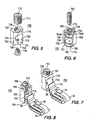
- a non-symmetrical aluminum terminal collar 700 has a main body 710 with a transverse cable opening 712.
- a cable compression fastener 714 which has threads and which may be threaded downwardly into a similarly threaded hole 726 to abut any cables (not shown) which have been transversely fed through the hole or opening 712.
- An appropriate drive opening 716 is provided in the member 714 for screwing it down into the hole 716.
- the terminal securement nut 718 may be driven or threaded into hole 724 by way of suitable through drive hole 720.
- the main body 710 has a pair of main body beveled surfaces on the right and left at 728 and 730, respectively. There is also a rear transverse main body surface at 732 and a front parallel transverse main body surface 733, which abuts and is between the beveled regions 728 and 730.
- a non-symmetrical steel terminal collar 750 embodiment of the invention is depicted.
- a main body 752 of the steel terminal collar 750 having a first side 754, a top 756, a second and parallel side to the first side 758 and bottom 760.
- a lower movable cable compression plate 762 which is disposed within the perimeter of the aforementioned sides, top and bottom and is movable up and down therein for compressing cables against an upper movable compression plate 763, which is oppositely disposed from the lower one.
- There is provided a locking tab 764 which fits into a hole or opening 764A in side 758 for completely securing the top 756 of collar to the side 758 of the collar.
- a threaded cable compression bolt 766 which may be driven downwardly through a complimentary threaded hole 768 in the top 756 of the main body 752.
- a threaded rider member 770 is disposed on the bottom thereof and it links up with a threaded hole or opening 763A in the movable upper cable rider member 763.
- the steel body terminal 750 may be utilized as a line terminal 750B and as a load terminal 750A.
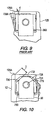
- Figures 7 and 8 show the disposition of the members 700 and 750 on terminals 36 of u-shape members 34 with the fixed contact 30. Insulation 715M disposed between the contact 30 and the terminal 36 in each case.
- FIG 76 a complimentary pocket seat in the circuit breaker case 12 for seating either of the collar embodiments therein. Because the seat 776 is non-symmetrical having bevels on the front but not on the back, the terminals can only be seated therein in one direction or one orientation, which is a feature of the present invention. Another feature of the present invention lies in the enhanced voltage separation caused by the bevels or confers 728 and 730.
- Figure 9 shows a prior art arrangement in which, prior art main body 728A is not beveled as in the present invention.
- the distance between the conductive corner 728A of the collar and the nearest point 12BB on the non-conductive casing 12B for the terminal arrangement 36B is represented by 'd'.
- the arrangement utilizing the member 700 for example is such that the distance 'D' between the bevel 730 ,for example, and the nearest, closest corner 12AA is significantly larger than the distance 'd'.
Landscapes
- Breakers (AREA)
Description
- The subject matter of this invention is related generally to molded case circuit breakers and more specifically to terminal collars for molded case circuit breakers.
- Molded case circuit breakers are well known in the art as exemplified by
U.S. Patent 5,910,760 issued June 8, 1999 to Malingowski et al. , entitled "Circuit Breaker with Double Rate Spring" and assigned to the assignee of the present application. - Molded case circuit breakers include a set of separable main contacts, one of which is usually fixed and one of which is movable for automatically opening upon the occurrence of an overload or short circuit electrical current in the network which the circuit breaker is provide to protect. The separable main contacts are opened as a result of the functioning of a latched operating mechanism, which is interconnectable by way of an operating handle to a region outside of the circuit breaker. The operating handle may be used to trip the circuit breaker manually or to reset and close the circuit breaker contacts once they have been opened automatically. The reset action is required because circuit breakers must be mechanically charged to be in a state to reopen immediately upon closure in the event that the fault which cause the tripping in the first place has not disappeared. The reset action charges the circuit breaker for that purpose. Molded case circuit breakers have trip units, which are often removably insertable in the circuit breaker case. The trip unit in addition has at least two calibratable functions, one of which is generally identified as thermal tripping and the other of which is generally identified as magnetic tripping. The trip unit includes a rotatable trip bar, which when rotated will actuate a latchable tripping operation within the operating mechanism to automatically open the circuit breaker contacts. The rotatable trip bar is usually actuated in one of two ways. The first way is in response to what is called a magnetic tripping of the circuit breaker. This occurs when the amount of current flowing through the separable main contacts of the circuit breaker is so high as to represent a potential catastrophic failure and which therefore requires exceedingly quick opening action of the circuit breaker. In such a case a electron magnetic core, which produces magnetic flux in proportion to the amount of electrical current flowing through the separable main contacts attracts a movable armature, the movement of which eventually causes the trip bar to move to thus cause the tripping action. The second tripping occurrence is in response to a relatively low amount of overload current, which eventually will cause overheating of the electrical wires in the circuit to be protected, but which does not necessitate the instantaneous action a short circuit requires and thus does not require the magnetic action spoken of previously. In this case a bi-metal element is heated by a heater element which conducts the electrical current flowing through the separable main contacts. As the bi-metal element flexes or moves it impinges upon the tripping bar causing it to flex and move correspondingly, until eventually a point is reached in which the tripping bar causes the circuit breaker to unlatch and trip automatically. Both the magnetic trip mechanism and the thermal trip mechanism usually require initial calibration.
- In one half of an AC cycle, the electrical current flows through the circuit interrupter from the load by way of a terminal collar to the load terminal of the circuit breaker and from there into the trip unit where it flows through the previously mentioned heater which in turn is serially connected to the electron magnetic member of the magnetic trip device. From there it is interconnected by way of a flexible cable to one end of a moveable contact arm and from there to the main contact on the moveable contact arm. When the contact arm is closed, it is closed upon a fixed contact which is supported usually on u-shaped conductor, which in turn is interconnected with a line terminal and there to the line terminal collar and finally to the electrical line. In addition the circuit breaker usually has an arc chute for assisting in diminishing the electrical arc drawn between the separating contacts during the opening operation for extinguishing of the arc. The circuit breaker also has a slot motor arrangement, which is utilized to interact magnetically with the electrical current flowing in the opening contact arm to accelerate the opening of the contact arm magnetically. The operating mechanism usually consists of a series of levers and linkages, which are interconnected with the separable main moveable contact arm, the handle mechanism, and by way of a latch arrangement with the aforementioned trip bar. Description and operation of all of the above may be found in the previous mentioned, incorporated by reference '760 patent.
- Molded case circuit breakers usually have collars which interface the line and load terminals of the circuit breaker with electrical cables. Such a collar may be found in
U.S. 5,206,789 issued April 27, 1993 to Barbry et al. , entitled "Terminal Assembly for a Circuit Breaker and Similar Apparatus" and assigned to the assignee of the present application. Other examples of such arrangements may be found inU.S. Patent 5,005,104 . In the past these collars have been basically symmetrical in nature. That it is, the functions, equally well in a number of orientations. It would be advantageous, however, if a collar could be found which had the same interconnection and electrical isolation facility as the previous collars, but which could be reduced in size to thus allow the size of the overall breaker to be reduced. It would be further advantageous if the circuit breaker casing was adapted to having this collar integrated into it. - In accordance with the present invention a circuit interrupter device, as set forth in claims 1, and a circuit interrupter device, as set forth in claim 3, are provided. Embodiments of the invention are described in the dependent claims.
- In accordance with the invention there is provided a circuit interrupter having a housing. There is an operating mechanism disposed within the housing. Also, separable contacts are disposed within the housing in cooperation with the operating mechanism for being opened by the operating mechanism, a terminal is interconnected with the separable contacts for providing an electrical conduction path from a region outside of the housing to the separable contacts. The terminal has a non-symmetrically shaped terminal collar connected thereto with a region of relatively smaller dimension relative to a region of relatively larger dimension, the closest uninsulated path between the non-symmetrically shaped terminal collar and the nearest external portion of the housing being from the region of relatively smaller dimension.
- In accordance with the invention, reference may be had to the preferred embodiment thereof, shown in the accompanying drawings in which:
-
Figure 1 is an orthogonal view of a three-phase molded case circuit breaker employing embodiments of the present invention; -
Figure 2 is a cut away side elevation section of the circuit breaker ofFig. 1 , depicting the circuit interrupter in the closed state; -
Figure 3 is a side elevation view similar to that shown inFig. 2 , concentrating on the circuit breaker operating mechanism and trip unit; -
Figure 4 is similar toFig. 2 , but depicts the circuit interrupter in the tripped state; -
Figure 5 shows an orthogonal view in exploded form of an aluminum line or load collar; -
Figure 6 shows an arrangement similar to that shown inFig. 5 for a steel line or load collar; -
Figure 7 shows an orthogonal view of the aluminum collar ofFig. 5 interconnected with the fixed contact arrangement of the circuit interrupter ofFig. 1 ; -
Figure 8 shows an arrangement similar to that shown inFig. 7 for the steel collar ofFig. 6 ; -
Figure 9 shows a prior art view in cross-section, partially broken away of the spacing between a prior art collar and a circuit breaker case edge; -
Figure 10 shows an arrangement similar to that shown inFig. 9 for the collar of the present invention; and -
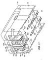
Figure 11 shows a bottom view of the circuit interrupter apparatus ofFig. 1 in orthogonal view with the collars ofFigures 5 through 8 disposed therein. - Referring now to the drawings and
Figures 1 through 4 in particular, there is shown a molded case circuit breaker orinterrupter 10 having amain base 12 andprimary cover 14. Attached to theprimary cover 14 is asecondary cover 16. Ahandle 18 extends through asecondary escutcheon 22A in thesecondary cover 16 and alignedprimary escutcheon 22B in theprimary cover 14. Anoperating mechanism 20 is interconnected with thehandle 18 for opening and closing separable main contacts in a manner which will be described hereinafter. This circuit breaker has aline end 15 andload end 17. The circuit breaker or interrupter includes aremovable trip unit 24.Removable trip unit 24 has an underlapping lip 24X, the purpose of which will be described hereinafter. There are also depicted aload terminal 26, a right side accessory region orpocket 27 and a left side accessory pocket orregion 31. - Referring now more specifically to
Figures 2 ,3 and4 , there are depicted a separablemovable contact 28 disposed upon amoveable contact arm 32 and a fixedcontact 30 disposed upon a fixed contact support or u-shapedmember 34.Line terminal 36 is disposed to the left inFigure 2 , for example, at theline end 15 of the circuit interrupter in a terminal cave orpocket 29. Aload terminal 26 is disposed to the right inFigure 2 , for example, in a load terminal cave orpocket 29. To the left on theline terminal 36 is disposed aline terminal collar 38 which will be described in more detail hereinafter, and to the right is provided a load terminal jumper-to-movablecontact arm conductor 802. Connected toconductor 802 is aflexible conductor 39, which is interconnected withmovable contact arm 32 as shown schematically. The load terminal jumper orframe conductor 802 is interconnected at its other end with abi-metal heater 180, which in turn is interconnected at its other end with the terminal 26. Consequently, when the circuit interrupter separablemain contacts line conductor 26 throughbi-metal heater 180, through load terminal jumper orframe conductor 802, throughflexible conductor 39, through themovable contact arm 32, throughcontact 28 to contact 30 and from there through the fixed contact support oru-shaped member 34 toline terminal 36. - There is provided a
operating mechanism 20 for assisting in opening and closing the separablemain contacts cradle 52, which is pivoted on one end at a cradle fixed pivotedpin 54 by way of anopening 54A in the cradle for placement of the cradle fixed pivoted pin therein. The cradle includes a cradle-to-side accessoryregion side protrusion 55. There is provided anupper toggle link 46 and alower toggle link 48. They are joined pivotally by an upper and lowertoggle link pin 50. There is provided a lower toggle link to movable contact arm main pivot assembleattachment pin 56, which is affixed to themovable contact arm 32 at anopening 56A. There is also a cradle to upper togglelink pivot pin 58, by which theupper toggle link 46 is placed in physical contact with thecradle 52. There is also provided a movable contact armmain pivot assembly 59, which movably, rotatably pivots on apivot 60. There is also provided aprimary frame latch 62 which operates or rotates on a primaryframe latch pivot 64. Theprimary frame latch 62 cooperates with asecondary frame latch 68, which rotates on a secondary frame latch pivot 70. The operating power for the tripping operating of the circuit breaker is provided by a charged maintoggle coil spring 72. The main toggle coil spring is interconnected with ahandle yoke 44 by way of a handleyoke attachment post 45. The other end of thespring 72 is attached to thetoggle link pin 50.Cradle 52 has acradle lip 73, which is captured or held in place by theprimary latch 62 when the separablemain contacts primary frame latch 62 has been actuated away from thecradle lip 73 in a manner which will be described hereinafter. There is provided a combination secondary-frame-latch-primary-frame-latch torsion spring 78, which exerts force against both latches sufficient to cause appropriate movement thereof at the appropriate time. The secondary frame latch has a laterally extendingtrip protrusion 79, the purpose of which will be described later hereinafter. Actuation of the primary and secondary frame latches occurs exclusively by way of the utilization of a resetable tripunit trip plunger 74, which is contained entirely within theremovable trip unit 24. The tripunit trip plunger 74 is controlled or latched by way of a plunger latch orinterference latch 75. Thesecondary frame latch 68 is in disposition to be struck by the moving trip unitplunger abutment surface 288. Upon opening of the separablemain contacts arc chute 77. Thesecondary frame latch 68 has abottom portion 89, upon which is disposed anarcuate stop surface 90 for theprimary frame latch 62. There is also provided above that arcuate stop surface and as part of the acruate stop member alatch surface 92. - The operating mechanism described herein may be the same as found in
U.S. Patent 5,910,760 issued June 8, 1999 to Malingowski et al , entitled "Circuit Breaker with Double Rate Spring". Thought the primary and secondary frame latches are disposed within thecase 12, thetrip unit plunger 75 is responsible for initiating all tripping action from thetrip unit 24 into the region of thesecondary latch 68. Alternatively, thesecondary latch 68 may be actuated by a push-to-trip button in a manner, which will be described hereinafter. Thesecondary latch 68 is actuated to rotate to the left as shown inFigures 2 ,3 and4 , for example, indirection 81 about its pivot 70. As this occurs theacruate stop surface 90 for thesecondary frame latch 68 rotates away from the bottom of theprimary frame latch 62 until thelateral latch surface 92 rotates into a disposition to allow the bottom of theprimary frame latch 62 to rotate to the right under the force of thecradle 72. This causes theprimary frame latch 62 to clear thelip 73 of thecradle 52 to allow thecradle 52 to rotate upwardly about itspivot 54 in adirection 82 under the power of the now collapsingcoil spring 72 by way of the force exerted thereupon by theupper toggle link 46 acting against the cradle-to-upper-togglelink connecting pin 58. As thetoggle spring 72 relaxes, the upper and lower toggle links collapse, which in turn causes the lower toggle link to movable contactarm pivot assembly 56 to rotate upwardly in thedirection 86 about itspivot 60. This, of course, causes thecontact arm 32 to rotate similarly in thedirection 88, thus opening the separablemain contacts secondary frame latch 68 can be duplicated by causing secondary latch push-to-trip member side laterally extendingtrip protrusion 79 to rotate in thedirection 81 by operation of a push-to-trip member which will be described later hereinafter. Resetting of the circuit breaker is accomplished in a matter well known in the prior art and described and shown with respect to the aforementionedU.S. Patent 5,910,760 . The important part of the operation with respect to this feature is the movement of the secondaryframe latch point 76 in the direction opposite todirection 82, against theplunger face 288 in a manner, which will be described later hereinafter. However, if movement of theplunger face 288 in the rightward direction against its plunger spring, as will be described hereinafter, is prevented because of the latching of theplunger member 74, in a manner which will be described hereinafter, then the circuit breaker can not be reset. An important feature of the invention lies in the fact that the ultimate control of the resetting of the circuit breaker and tripping of the circuit breaker can be accomplished only from theremovable trip unit 24, rather than from theoperating mechanism 20. - An embodiment of the invention is shown in
Figures 5 through 11 . In particular there is shown inFigure 5 a non-symmetricalaluminum terminal collar 700. Thealuminum terminal collar 700 has amain body 710 with atransverse cable opening 712. There is provided acable compression fastener 714, which has threads and which may be threaded downwardly into a similarly threadedhole 726 to abut any cables (not shown) which have been transversely fed through the hole oropening 712. Anappropriate drive opening 716 is provided in themember 714 for screwing it down into thehole 716. There is provided a threadedhole 724 in the bottom of themain body 710 of the terminal 700 into which a threaded a lineterminal securement nut 718 may be upwardly threaded therein, through a portion of the circuit breaker case (not shown). There is provided a lateral terminal cut-out 722 on the bottom of the terminalmain body 710 for alignment with line conductor, such as will be described hereinafter. Theterminal securement nut 718 may be driven or threaded intohole 724 by way of suitable throughdrive hole 720. Themain body 710 has a pair of main body beveled surfaces on the right and left at 728 and 730, respectively. There is also a rear transverse main body surface at 732 and a front parallel transversemain body surface 733, which abuts and is between thebeveled regions - Referring to
Figure 6 , a non-symmetricalsteel terminal collar 750 embodiment of the invention is depicted. There is amain body 752 of thesteel terminal collar 750, having afirst side 754, a top 756, a second and parallel side to thefirst side 758 andbottom 760. There is a lower movablecable compression plate 762, which is disposed within the perimeter of the aforementioned sides, top and bottom and is movable up and down therein for compressing cables against an uppermovable compression plate 763, which is oppositely disposed from the lower one. There is provided alocking tab 764, which fits into a hole oropening 764A inside 758 for completely securing the top 756 of collar to theside 758 of the collar. There is provided a threadedcable compression bolt 766, which may be driven downwardly through a complimentary threadedhole 768 in the top 756 of themain body 752. A threadedrider member 770 is disposed on the bottom thereof and it links up with a threaded hole oropening 763A in the movable uppercable rider member 763. There is provided on the left and right, beveledshoulders beveled regions Figure 5 . By referring toFigure 2 , it can be seen that thesteel body terminal 750 may be utilized as aline terminal 750B and as aload terminal 750A. -
Figures 7 and 8 show the disposition of themembers terminals 36 ofu-shape members 34 with the fixedcontact 30. Insulation 715M disposed between thecontact 30 and the terminal 36 in each case. - Referring now to
Figures 9 and 10 , inFigure 10 , there is shown at 76 a complimentary pocket seat in thecircuit breaker case 12 for seating either of the collar embodiments therein. Because theseat 776 is non-symmetrical having bevels on the front but not on the back, the terminals can only be seated therein in one direction or one orientation, which is a feature of the present invention. Another feature of the present invention lies in the enhanced voltage separation caused by the bevels or confers 728 and 730.Figure 9 shows a prior art arrangement in which, prior artmain body 728A is not beveled as in the present invention. The distance between theconductive corner 728A of the collar and the nearest point 12BB on thenon-conductive casing 12B for theterminal arrangement 36B is represented by 'd'. However inFigure 10 , it can easily be seen that the arrangement utilizing themember 700 for example, is such that the distance 'D' between thebevel 730 ,for example, and the nearest, closest corner 12AA is significantly larger than the distance 'd'. - By referring to
Figure 11 , it can be seen that thecomplimentary pocket seat 776 in the circuit breaker case only allows a seating of either of theterminal arrangements circuit breaker case 12. This is another feature of the invention.
Claims (6)
- A circuit interrupter device (10), comprising:a housing corresponding to a circuit breaker case (12);operating mechanism means (20) disposed within said housing;separable contact means (28,30) disposed within said housing in cooperation with said operating mechanism means for being opened by said operating mechanism means;opening means (19) disposed within said housing in cooperation with said operating mechanism means for actuating said operating mechanism means to open said separable contact means, andterminal means interconnected with said separable contact means for providing an electrical conduction path from a region outside of said housing to said separable contact means,characterised in thatsaid terminal means has a terminal (26,36) with a collar (38;700;750) of non-symmetrical shape which is connected to said terminal with a region of relatively smaller dimension relative to a region of larger dimension,said housing having a terminal pocket (29) in which said collar is disposed and the pocket having a seat (776) in which said collar is captured.
- A device according to claim 1, characterised in that the collar has a chamfer (728, 730; 772, 774) which defines the region of relatively smaller dimension.
- A circuit interrupter device (10) according to claim 1, wherein:the separable contact means (28,30) comprise multi pole separable contact means (28,30) disposed within said housing in cooperation with said operating mechanism means for being opened by said operating means;opening means (19)disposed within said housing in cooperation with said operating mechanism means for actuating said operating mechanism means to open said separable contact means, and the terminal means comprise multi pole terminal means interconnected with said multi pole separable contact means for providing an electrical conduction path from a region outside of said housing to each pole of said multi pole separable contact means, each terminal of said multi pole terminal means has a collar (38;700;750) of non-symmetrical shape which is connected thereto with a region of relatively smaller dimension relative to a region of larger dimension, and between adjacent pairs of terminal collars are uninsulated lateral paths of electrical conduction, the shortest of which being between said regions of relatively smaller dimensions.
- A device according to claim 3, wherein the housing has adjacent terminal pockets (29) in each of which a respective one of the terminal collars is disposed.
- A device according to claim 4, wherein each of the adjacent terminal pockets has a seat (776) in which each respective one of the terminal collars is captured.
- A device according to claim 3, 4 or 5, wherein each of the terminal collars has a chamfer (728, 730; 772, 774) defining the region of relatively smaller dimension.
Applications Claiming Priority (2)
| Application Number | Priority Date | Filing Date | Title |
|---|---|---|---|
| US377018 | 1995-01-20 | ||
| US09/377,018 US6084188A (en) | 1999-08-18 | 1999-08-18 | Circuit interrupter with non-symmetrical terminal collar |
Publications (2)
| Publication Number | Publication Date |
|---|---|
| EP1077458A1 EP1077458A1 (en) | 2001-02-21 |
| EP1077458B1 true EP1077458B1 (en) | 2010-12-29 |
Family
ID=23487431
Family Applications (1)
| Application Number | Title | Priority Date | Filing Date |
|---|---|---|---|
| EP00116257A Expired - Lifetime EP1077458B1 (en) | 1999-08-18 | 2000-08-08 | Circuit interrupter with non-symmetrical terminal collar |
Country Status (6)
| Country | Link |
|---|---|
| US (1) | US6084188A (en) |
| EP (1) | EP1077458B1 (en) |
| BR (1) | BR0003868A (en) |
| CA (1) | CA2316488C (en) |
| DE (1) | DE60045433D1 (en) |
| ES (1) | ES2355603T3 (en) |
Families Citing this family (13)
| Publication number | Priority date | Publication date | Assignee | Title |
|---|---|---|---|---|
| US6274833B1 (en) * | 2000-02-18 | 2001-08-14 | Siemens Energy & Automation, Inc. | Plug-in trip unit joint for a molded case circuit breaker |
| US6280264B1 (en) * | 2000-12-28 | 2001-08-28 | Eaton Corporation | Terminal connector securing wire with a wide range of diameters to a conductor of an electric power switch and an electric power switch incorporating the terminal connector |
| US6437268B1 (en) * | 2001-01-31 | 2002-08-20 | Square D Company | Circuit breaker terminal connector |
| US7009132B1 (en) * | 2004-09-03 | 2006-03-07 | Eaton Corporation | Terminal assembly for vented circuit breaker and circuit breaker incorporating same |
| US7796369B2 (en) * | 2006-05-01 | 2010-09-14 | Siemens Industry, Inc. | Devices, systems, and methods for shunting a circuit breaker |
| US7578711B2 (en) * | 2007-04-13 | 2009-08-25 | Siemens Energy & Automation, Inc. | Devices, systems, and method for coupling electrical conductors |
| EP2109129B1 (en) * | 2008-04-11 | 2016-03-30 | ABB Technology AG | Medium voltage circuit breaker with integrated electronic protection unit |
| DE102010015304A1 (en) * | 2010-04-15 | 2011-10-20 | Siemens Aktiengesellschaft | Clamp for connecting insulated electric guard with multipolar electrical switch, has marker attached on outer surface of clamp to indicate length when marker is stripped at guard ends inserted into recesses |
| US9502782B2 (en) | 2013-10-09 | 2016-11-22 | Rockwell Automation Technologies, Inc. | System and method for transmitting power through a plug-in unit |
| US9270033B2 (en) * | 2013-12-19 | 2016-02-23 | Siemens Industry, Inc. | Lug retention arrangement |
| US9299523B1 (en) * | 2014-12-12 | 2016-03-29 | Eaton Corporation | Switching device assembly and adapter assembly therefor |
| USD796455S1 (en) * | 2016-06-15 | 2017-09-05 | Eaton Corporation | Electrical terminal |
| US20230387612A1 (en) * | 2022-05-31 | 2023-11-30 | Erico International Corporation | Grounding Connector |
Family Cites Families (8)
| Publication number | Priority date | Publication date | Assignee | Title |
|---|---|---|---|---|
| US3748420A (en) * | 1972-04-18 | 1973-07-24 | Westinghouse Electric Corp | Terminal member for circuit interrupter |
| US5005104A (en) * | 1990-08-16 | 1991-04-02 | Westinghouse Electric Corp. | Clip-connected terminal conductor assembly |
| US5150091A (en) * | 1990-11-08 | 1992-09-22 | General Electric Company | Bus cover and lug cover for a molded case circuit breaker |
| US5107396A (en) * | 1991-06-03 | 1992-04-21 | General Electric Company | Circuit breaker combined terminal lug and connector |
| US5206789A (en) * | 1992-03-05 | 1993-04-27 | Westinghouse Electric Corp. | Terminal assembly for a circuit breaker and similar apparatus |
| US5493092A (en) * | 1994-10-12 | 1996-02-20 | Eaton Corporation | Shield for a line side of a circuit breaker for supporting cable and deflecting ionized gases |
| US5927484A (en) * | 1997-05-28 | 1999-07-27 | Eaton Corporation | Circuit breaker with welded contact interlock, gas sealing cam rider and double rate spring |
| US5978208A (en) * | 1997-12-12 | 1999-11-02 | Eaton Corporation | Circuit breaker arrangement with improved terminal collar having interlock sections |
-
1999
- 1999-08-18 US US09/377,018 patent/US6084188A/en not_active Expired - Lifetime
-
2000
- 2000-08-08 EP EP00116257A patent/EP1077458B1/en not_active Expired - Lifetime
- 2000-08-08 ES ES00116257T patent/ES2355603T3/en not_active Expired - Lifetime
- 2000-08-08 DE DE60045433T patent/DE60045433D1/en not_active Expired - Lifetime
- 2000-08-17 CA CA002316488A patent/CA2316488C/en not_active Expired - Fee Related
- 2000-08-17 BR BR0003868-7A patent/BR0003868A/en not_active IP Right Cessation
Also Published As
| Publication number | Publication date |
|---|---|
| US6084188A (en) | 2000-07-04 |
| EP1077458A1 (en) | 2001-02-21 |
| CA2316488C (en) | 2008-09-23 |
| DE60045433D1 (en) | 2011-02-10 |
| CA2316488A1 (en) | 2001-02-18 |
| ES2355603T3 (en) | 2011-03-29 |
| BR0003868A (en) | 2001-04-03 |
Similar Documents
| Publication | Publication Date | Title |
|---|---|---|
| EP1212773B1 (en) | Circuit breaker with easily installed removable trip unit | |
| EP0887831B1 (en) | Circuit breaker with welded contact inter-lock, gas sealing cam rider double rate spring | |
| US6052047A (en) | Circuit interrupter with covered accessory case, adjustable under voltage relay, self-retaining collar and one-piece rail attachment | |
| EP0175976A2 (en) | Circuit breaker with bimetal and calibration adjusting means | |
| EP1077458B1 (en) | Circuit interrupter with non-symmetrical terminal collar | |
| KR920006061B1 (en) | Solenoid Moveable Actuator of Circuit Breaker | |
| AU646162B2 (en) | Circuit breaker with interlock for welded contacts | |
| EP0146033A2 (en) | Electric circuit breaker with improved operating mechanism | |
| EP0887832B1 (en) | Circuit interrupter with plasma arc acceleration chamber and contact arm housing | |
| US6750743B1 (en) | Integrated thermal and magnetic trip unit | |
| US6747534B1 (en) | Circuit breaker with dial indicator for magnetic trip level adjustment | |
| AU661998B2 (en) | Circuit breaker with positive on/off interlock | |
| US6137386A (en) | Circuit breaker with trip unit mounted tripping plunger and latch therefore | |
| US4594491A (en) | Molded case circuit breaker with a trip mechanism having an intermediate latch lever | |
| US6100777A (en) | Multi-pole circuit breaker with multiple trip bars | |
| US6229418B1 (en) | Circuit breaker with lockable trip unit | |
| US4553116A (en) | Molded case circuit breaker with resettable combined undervoltage and manual trip mechanism | |
| US20040227602A1 (en) | Circuit breaker magnetic trip assembly | |
| US4620171A (en) | Molded case circuit breaker with resettable combined undervoltage and manual trip mechanism | |
| EP0923102A2 (en) | Intermediate latch for a molded case circuit breaker | |
| US6137385A (en) | Circuit breaker with side wall opening for a separate auxiliary device actuation lever | |
| US5430422A (en) | Circuit breaker with anti-shock-off blocking mechanism |
Legal Events
| Date | Code | Title | Description |
|---|---|---|---|
| PUAI | Public reference made under article 153(3) epc to a published international application that has entered the european phase |
Free format text: ORIGINAL CODE: 0009012 |
|
| AK | Designated contracting states |
Kind code of ref document: A1 Designated state(s): DE ES FR GB IT |
|
| AX | Request for extension of the european patent |
Free format text: AL;LT;LV;MK;RO;SI |
|
| 17P | Request for examination filed |
Effective date: 20010713 |
|
| AKX | Designation fees paid |
Free format text: DE ES FR GB IT |
|
| 17Q | First examination report despatched |
Effective date: 20061227 |
|
| GRAP | Despatch of communication of intention to grant a patent |
Free format text: ORIGINAL CODE: EPIDOSNIGR1 |
|
| GRAS | Grant fee paid |
Free format text: ORIGINAL CODE: EPIDOSNIGR3 |
|
| GRAA | (expected) grant |
Free format text: ORIGINAL CODE: 0009210 |
|
| AK | Designated contracting states |
Kind code of ref document: B1 Designated state(s): DE ES FR GB IT |
|
| REG | Reference to a national code |
Ref country code: GB Ref legal event code: FG4D |
|
| REF | Corresponds to: |
Ref document number: 60045433 Country of ref document: DE Date of ref document: 20110210 Kind code of ref document: P |
|
| REG | Reference to a national code |
Ref country code: DE Ref legal event code: R096 Ref document number: 60045433 Country of ref document: DE Effective date: 20110210 |
|
| REG | Reference to a national code |
Ref country code: ES Ref legal event code: FG2A Ref document number: 2355603 Country of ref document: ES Kind code of ref document: T3 Effective date: 20110329 |
|
| PLBE | No opposition filed within time limit |
Free format text: ORIGINAL CODE: 0009261 |
|
| STAA | Information on the status of an ep patent application or granted ep patent |
Free format text: STATUS: NO OPPOSITION FILED WITHIN TIME LIMIT |
|
| 26N | No opposition filed |
Effective date: 20110930 |
|
| REG | Reference to a national code |
Ref country code: DE Ref legal event code: R097 Ref document number: 60045433 Country of ref document: DE Effective date: 20110930 |
|
| PGFP | Annual fee paid to national office [announced via postgrant information from national office to epo] |
Ref country code: DE Payment date: 20130902 Year of fee payment: 14 Ref country code: ES Payment date: 20130806 Year of fee payment: 14 |
|
| PGFP | Annual fee paid to national office [announced via postgrant information from national office to epo] |
Ref country code: FR Payment date: 20130725 Year of fee payment: 14 Ref country code: GB Payment date: 20130726 Year of fee payment: 14 |
|
| PGFP | Annual fee paid to national office [announced via postgrant information from national office to epo] |
Ref country code: IT Payment date: 20130819 Year of fee payment: 14 |
|
| REG | Reference to a national code |
Ref country code: DE Ref legal event code: R119 Ref document number: 60045433 Country of ref document: DE |
|
| GBPC | Gb: european patent ceased through non-payment of renewal fee |
Effective date: 20140808 |
|
| PG25 | Lapsed in a contracting state [announced via postgrant information from national office to epo] |
Ref country code: IT Free format text: LAPSE BECAUSE OF NON-PAYMENT OF DUE FEES Effective date: 20140808 |
|
| REG | Reference to a national code |
Ref country code: DE Ref legal event code: R119 Ref document number: 60045433 Country of ref document: DE Effective date: 20150303 |
|
| REG | Reference to a national code |
Ref country code: FR Ref legal event code: ST Effective date: 20150430 |
|
| PG25 | Lapsed in a contracting state [announced via postgrant information from national office to epo] |
Ref country code: GB Free format text: LAPSE BECAUSE OF NON-PAYMENT OF DUE FEES Effective date: 20140808 Ref country code: DE Free format text: LAPSE BECAUSE OF NON-PAYMENT OF DUE FEES Effective date: 20150303 |
|
| PG25 | Lapsed in a contracting state [announced via postgrant information from national office to epo] |
Ref country code: FR Free format text: LAPSE BECAUSE OF NON-PAYMENT OF DUE FEES Effective date: 20140901 |
|
| REG | Reference to a national code |
Ref country code: ES Ref legal event code: FD2A Effective date: 20150925 |
|
| PG25 | Lapsed in a contracting state [announced via postgrant information from national office to epo] |
Ref country code: ES Free format text: LAPSE BECAUSE OF NON-PAYMENT OF DUE FEES Effective date: 20140809 |