EP1077345A2 - Headlamp for vehicle - Google Patents
Headlamp for vehicle Download PDFInfo
- Publication number
- EP1077345A2 EP1077345A2 EP00117650A EP00117650A EP1077345A2 EP 1077345 A2 EP1077345 A2 EP 1077345A2 EP 00117650 A EP00117650 A EP 00117650A EP 00117650 A EP00117650 A EP 00117650A EP 1077345 A2 EP1077345 A2 EP 1077345A2
- Authority
- EP
- European Patent Office
- Prior art keywords
- reflector
- shading
- separated
- headlamp
- edge
- Prior art date
- Legal status (The legal status is an assumption and is not a legal conclusion. Google has not performed a legal analysis and makes no representation as to the accuracy of the status listed.)
- Withdrawn
Links
- 230000003287 optical effect Effects 0.000 claims description 4
- 238000000926 separation method Methods 0.000 description 32
- 210000000887 face Anatomy 0.000 description 4
- 230000002542 deteriorative effect Effects 0.000 description 1
- 230000004313 glare Effects 0.000 description 1
- 229910052736 halogen Inorganic materials 0.000 description 1
- 229910052751 metal Inorganic materials 0.000 description 1
- 239000002184 metal Substances 0.000 description 1
- 229910001507 metal halide Inorganic materials 0.000 description 1
- 150000005309 metal halides Chemical class 0.000 description 1
- 229910052721 tungsten Inorganic materials 0.000 description 1
- 239000010937 tungsten Substances 0.000 description 1
- -1 tungsten halogen Chemical class 0.000 description 1
Images



Classifications
-
- B—PERFORMING OPERATIONS; TRANSPORTING
- B60—VEHICLES IN GENERAL
- B60Q—ARRANGEMENT OF SIGNALLING OR LIGHTING DEVICES, THE MOUNTING OR SUPPORTING THEREOF OR CIRCUITS THEREFOR, FOR VEHICLES IN GENERAL
- B60Q1/00—Arrangement of optical signalling or lighting devices, the mounting or supporting thereof or circuits therefor
- B60Q1/02—Arrangement of optical signalling or lighting devices, the mounting or supporting thereof or circuits therefor the devices being primarily intended to illuminate the way ahead or to illuminate other areas of way or environments
- B60Q1/04—Arrangement of optical signalling or lighting devices, the mounting or supporting thereof or circuits therefor the devices being primarily intended to illuminate the way ahead or to illuminate other areas of way or environments the devices being headlights
-
- F—MECHANICAL ENGINEERING; LIGHTING; HEATING; WEAPONS; BLASTING
- F21—LIGHTING
- F21S—NON-PORTABLE LIGHTING DEVICES; SYSTEMS THEREOF; VEHICLE LIGHTING DEVICES SPECIALLY ADAPTED FOR VEHICLE EXTERIORS
- F21S41/00—Illuminating devices specially adapted for vehicle exteriors, e.g. headlamps
- F21S41/60—Illuminating devices specially adapted for vehicle exteriors, e.g. headlamps characterised by a variable light distribution
- F21S41/67—Illuminating devices specially adapted for vehicle exteriors, e.g. headlamps characterised by a variable light distribution by acting on reflectors
- F21S41/675—Illuminating devices specially adapted for vehicle exteriors, e.g. headlamps characterised by a variable light distribution by acting on reflectors by moving reflectors
Definitions
- the present invention relates to a headlamp for a vehicle where a movable reflector is moved to change a brightness intensity distribution pattern, and in particular to a headlamp for a vehicle where, even when a movable reflector is moved, an air gap does not occur between the movable reflector and another reflector.
- JP-A Japanese Patent Application Laid-Open
- 5-286392 Japanese Patent Application Laid-Open
- air gaps are respectively generated in an opening manner between an outer face (a face opposed to the reflecting face) side of the separation edge of the fixed reflector and an inner face (the reflecting face) side of the separation edge of the movable reflector, and between an inner face (the reflecting face) side of the separation edge of the fixed reflector and an outer face (a face opposed to the reflecting face) side of the separation edge of the movable reflector.
- An object of the present invention is to provide a headlamp for a vehicle which improves drawback caused by an air gap between a movable reflector and another reflector.
- a first aspect of the present invention provides a headlamp for a vehicle.
- the headlamp has a first reflector; and a second reflector for cooperating with the first reflector to set up a brightness intensity distribution pattern.
- the second reflector and the first reflector define an air gap therebetween.
- the second reflector is flanged for shading the air gap.
- the first reflector is flanged for shading the air gap.
- a flanged part of the second reflector is positioned at an edge of the second reflector.
- the first reflector is to be moved relative to the second reflector.
- the second reflector is to be moved relative to the first reflector.
- a second aspect of the invention provides a headlamp for a vehicle.
- the headlamp has a light source bulb.
- the headlamp has a reflector for reflecting light rays from the light source bulb to set up a brightness intensity distribution pattern.
- the reflector is separated in a movable reflector part and a fixed reflector part.
- the movable reflector part has a first separated edge.
- the fixed reflector part has a second separated edge in opposition to the first separated edge.
- the headlamp has a driving means for moving the movable reflector part relative to the fixed reflector part to change a brightness intensity distribution pattern of light rays from the light source bulb.
- the headlamp has a shading flange for shading an air gap between the first separated edge and the second separated edge.
- the shading flange is wider than a movement range of the movable reflector part.
- the shading flange projects from the first separated edge.
- the shading flange always overlaps with the second separated edge.
- the shading flange projects from the second separated edge.
- the shading flange always overlaps with the first separated edge.
- a pair of shading flanges project from the first separated edge and the second separated edge.
- the first separated edge and the second separated edge are positioned above an optical axis of the light source bulb.
- the light source bulb is a discharge lamp.
- a third aspect of the invention provides a headlamp for a vehicle.
- the headlamp has a light source bulb.
- the headlamp has a reflector for reflecting light rays from the light source bulb to set up a brightness intensity distribution pattern.
- the reflector is separated in a plurality of reflector parts.
- the headlamp has a driving means for moving at least one movable reflector part of reflector parts to change a brightness intensity distribution pattern of light rays from the light source bulb.
- the headlamp has a shading flange projecting from at least one of separated edges of a movable reflector part and another reflector part, the shading flange being wider than a movement range of the movable reflector, the shading flange and a separated edge always overlap with each other.
- a shading flange wider than a movement range of a movable reflector part always overlaps the first separated edge of the movable reflector part or a second separated edge of the fixed reflector part. Accordingly, even when the movable reflector part is moved, the shading flange shades an air gap between the movable reflector part and the fixed reflector part, so that a reflected light does not project front the air gap, for example.
- the drawback due to the gap occurrence can be solved.
- a light source bulb 1 is, for example, a discharge lamp (a high pressure metal vapor discharge lamp such as a metal halide lamp or the like, high intensity discharge lamp (HID) or the like), and it is detachably attached to a fixed reflector 2 described later through a socket 10.
- a discharge lamp a high pressure metal vapor discharge lamp such as a metal halide lamp or the like, high intensity discharge lamp (HID) or the like
- HID high intensity discharge lamp
- the light source bulb another bulb other than this example, for example, a tungsten halogen lamp, an incandescent lamp or the like may be used.
- the fixed reflector 2 and a movable reflector 3 are structured by separating a reflector, which has a generally circular shape (a lower portion is formed in a flat shape) as viewed from the front, in upper and lower members at its upper portion along a horizontal separation line.
- Reflecting faces 20 and 30 are respectively provided on inside faces of the fixed reflector 2 and the movable reflector 3.
- the fixed reflector 2 is fixed to a lamp housing (not shown).
- the light source bulb 1 is detachably attached to the fixed reflector 2.
- a shade 4 and a bracket 5 are respectively fixed to the fixed reflector 2 by screws 40, 50.
- the movable reflector 3 is mounted to the bracket 5 through a holder 51 rotatably (movably) about an axis M-M which is substantially at a right angle to an optical axis Z-Z.
- Driving means 6 is mounted to the bracket 5 by screws 60.
- the driving means 6 rotates the movable reflector 3 relative to the fixed reflector 2 and the bracket 5 about the axis M-M, for example, in an interlocking manner with the steering wheel (not shown) of an automobile (not shown).
- the light source bulb 1, the fixed reflector 2, the movable reflector 3, the shade 4, the bracket 5, the holder 50 and the driving means 6 are disposed inside a light chamber (not shown) defined by the lamp housing and a front lens or a front cover (not shown), thereby structuring a headlamp for an automobile.
- the headlamp 100 for an automobile thus structured is, as shown in Fig. 5, equipped on each of left and right sides of a front portion of the automobile.
- Shading flanges 22, 32 are provided at outer face side of separation edges 21 and 31 of a fixed reflector 2 and a movable reflector 3 integrally therewith.
- Each of the shading flanges 22, 32 is formed in a shape of a portion of an annular shape (so-called railway rule) and it has an area and shape wider than a movement range of the movable reflector 3. Then, the separation edges 21, 31 and the shading flanges 22, 32 are always overlapped with each other.
- the shading flanges 22, 33 may are provided at a part of the outer face side of separation edges 21, 31.
- the predetermined brightness intensity distribution pattern is controlled by a set of only the reflecting faces 20 and 30, a set of the reflecting faces 20, 30 and the front lens, or only the front lens.
- the driving means 6 is actuated and the movable reflector 3 is rotated left or right about the axis M-M, so that a portion (a portion of the brightness intensity distribution pattern corresponding to the reflecting face 30 of the movable reflector 3) of the brightness intensity distribution pattern is swung left or right and the brightness intensity distribution pattern is changed.
- air gaps are portions "C" (diagonal line portions in Fig. 4) between the separation edge 21 of the fixed reflector 2 (shown with a solid line In Fig. 4) and the separation edge 31 of the movable reflector 3 (shown with a double dotted bold line In Fig. 4).
- the portions "C” are shaded by the shading flanges 22 and 32. That is, on the left side in Fig. 4, the portion “C” between the outer face (the face opposed to the reflecting face 20) of the separation edge 21 of the fixed reflector 2 and an inner face (the reflecting face 30) of the separation edge 31 of the movable reflector 3 is overlapped with the shading flange 22 of the fixed reflector 2 to be shaded.
- the portion "C" between the inner face (the reflecting face 20) of the separation edge 21 of the fixed reflector 2 and the outer face (the face opposed to the reflecting face 30) of the separation edge 31 of the movable reflector 3 is overlapped with the shading flange 32 of the movable reflector 3 to be shaded.
- the shading flanges 22, 23 are provided at both of the separation edges 21, 31 of the fixed reflector 2 and the movable reflector 3, even when the movable reflector 3 is moved left or right relative to the fixed reflector 2 in a swinging manner, the gap or portion "C" between the separation edges 21, 31 of the fixed reflector 2 and the movable reflector 3 is securely shaded by the shading flanges 22, 32 of both the fixed reflector 2 and the movable reflector 3, so that occurrence of the gap can securely be prevented.
- the horizontal separation lines of the fixed reflector 2 and the movable reflector 3, namely the separation edges 21, 31 are positioned above the optical axis Z-Z, even when light from the light source bulb 1 is incident on the horizontal separation lines, particularly the shading flange 32 of the separation edge 31 of the movable reflector 3 positioned on the upper side, the light is reflected downward so that glare light can be prevented from occurring.
- the shading flange 22 is provided at the separation edge 21 of the fixed reflector 2 positioned on the lower side, when the headlamp for an automobile of the present invention is viewed front the front thereof (in this case, since the height of human eyes is higher than that of the headlamp for an automobile, a person looks down obliquely at the headlamp), his/her eyes coming obliquely from above are shaded by the shading flange 22 of the fixed reflector 2.
- the shading flange 32 is not provided at the separation edge 31 of the movable reflector 3 positioned above the fixed reflector, and a gap occurs between the shading flange 22 of the fixed reflector 2 and the separation edge 31 of the movable reflector 3, the interior member positioned on the back sides of the reflectors 2, 3 can not be seen.
- one of the reflectors which have been separated in two members is employed as the fixed reflector 2 while the other is employed as the movable reflector 3.
- both the reflectors may be employed as movable reflectors as disclosed in the above-mentioned publication.
- the reflector is separated into two reflector members, but it may be separated into three or more reflector members.
- the shading flanges 22, 32 are provided at both the separation edges 21, 31 of the fixed reflector 2 and the movable reflector 3.
- the shading flange 22 or 32 may be provided at either one of the separation edge 21 of the fixed reflector 2 and the separation edge 31 of the movable reflector 3.
Landscapes
- Engineering & Computer Science (AREA)
- General Engineering & Computer Science (AREA)
- Mechanical Engineering (AREA)
- Non-Portable Lighting Devices Or Systems Thereof (AREA)
- Lighting Device Outwards From Vehicle And Optical Signal (AREA)
Abstract
Description
- The present invention relates to a headlamp for a vehicle where a movable reflector is moved to change a brightness intensity distribution pattern, and in particular to a headlamp for a vehicle where, even when a movable reflector is moved, an air gap does not occur between the movable reflector and another reflector.
- As the headlamp for an automobile, there is one which has been disclosed, for example, in Japanese Patent Application Laid-Open (JP-A) No. 5-286392 publication. It should be noted that the headlamp described in this publication has a structure where a main reflector and a sub-reflector having two separated members are moved together.
- However, in the above-mentioned conventional headlamp for an automobile, since the reflector is merely separated into the fixed reflector and the movable reflector, when the movable reflector is moved or rotated relative to the fixed reflector, there occurs an air gap between a separation edge of the fixed reflector and a separation edge of the movable reflector.
- That is, air gaps are respectively generated in an opening manner between an outer face (a face opposed to the reflecting face) side of the separation edge of the fixed reflector and an inner face (the reflecting face) side of the separation edge of the movable reflector, and between an inner face (the reflecting face) side of the separation edge of the fixed reflector and an outer face (a face opposed to the reflecting face) side of the separation edge of the movable reflector.
- When the gap is generated, there occurs a drawback regarding appearance of the lamp because such an interior member as a wire, a screw or the like positioned on back sides of the fixed reflector and the movable reflector is seen from the front of the lamp. Also, light from the light source bulb leaks into the back sides of the fixed reflector and the movable reflector. Then, when the light source bulb is a discharge lamp like this example, there is such a drawback that parts of the headlamp may deteriorate due to ultraviolet light of the discharge lamp.
- An object of the present invention is to provide a headlamp for a vehicle which improves drawback caused by an air gap between a movable reflector and another reflector.
- In order to achieve the above object, a first aspect of the present invention provides a headlamp for a vehicle. The headlamp has a first reflector; and a second reflector for cooperating with the first reflector to set up a brightness intensity distribution pattern. The second reflector and the first reflector define an air gap therebetween. The second reflector is flanged for shading the air gap.
- Preferably, the first reflector is flanged for shading the air gap.
- Preferably, a flanged part of the second reflector is positioned at an edge of the second reflector.
- Preferably, the first reflector is to be moved relative to the second reflector.
- Preferably, the second reflector is to be moved relative to the first reflector.
- A second aspect of the invention provides a headlamp for a vehicle. The headlamp has a light source bulb. The headlamp has a reflector for reflecting light rays from the light source bulb to set up a brightness intensity distribution pattern. The reflector is separated in a movable reflector part and a fixed reflector part. The movable reflector part has a first separated edge. The fixed reflector part has a second separated edge in opposition to the first separated edge. The headlamp has a driving means for moving the movable reflector part relative to the fixed reflector part to change a brightness intensity distribution pattern of light rays from the light source bulb. The headlamp has a shading flange for shading an air gap between the first separated edge and the second separated edge.
- Preferably, the shading flange is wider than a movement range of the movable reflector part.
- Preferably, the shading flange projects from the first separated edge.
- Preferably, the shading flange always overlaps with the second separated edge.
- Preferably, the shading flange projects from the second separated edge.
- Preferably, the shading flange always overlaps with the first separated edge.
- Preferably, a pair of shading flanges project from the first separated edge and the second separated edge.
- Preferably, the first separated edge and the second separated edge are positioned above an optical axis of the light source bulb.
- Preferably, the light source bulb is a discharge lamp.
- A third aspect of the invention provides a headlamp for a vehicle. The headlamp has a light source bulb. The headlamp has a reflector for reflecting light rays from the light source bulb to set up a brightness intensity distribution pattern. The reflector is separated in a plurality of reflector parts. The headlamp has a driving means for moving at least one movable reflector part of reflector parts to change a brightness intensity distribution pattern of light rays from the light source bulb. The headlamp has a shading flange projecting from at least one of separated edges of a movable reflector part and another reflector part, the shading flange being wider than a movement range of the movable reflector, the shading flange and a separated edge always overlap with each other.
- As a result, in a headlamp for a vehicle of the present invention, a shading flange wider than a movement range of a movable reflector part always overlaps the first separated edge of the movable reflector part or a second separated edge of the fixed reflector part. Accordingly, even when the movable reflector part is moved, the shading flange shades an air gap between the movable reflector part and the fixed reflector part, so that a reflected light does not project front the air gap, for example. Thus, the drawback due to the gap occurrence can be solved.
- These and other features, aspects, and advantage of the present invention will become better under stood with regard to the following description, appended claims, and accompanying drawings where:
- Fig. 1 is a front view of a main portion of a headlamp for an automobile according to an embodiment of the present invention;
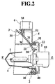
- Fig. 2 is a sectional view taken along line II-II in Fig. 1;
- Fig. 3 is a view seen along arrow III in Fig. 1;
- Fig. 4 is a sectional view taken along line IV-IV in Fig. 1 for explaining a state where a gap does not occur between a movable reflector and a fixed reflector even when the movable reflector is rotated; and
- Fig. 5 is a perspective view of an automobile for which a headlamp of an embodiment is adapted.
-
- An embodiment of a headlamp for an automobile of the present invention will be explained below with reference to Fig. 1 to Fig. 5.
- A
light source bulb 1 is, for example, a discharge lamp (a high pressure metal vapor discharge lamp such as a metal halide lamp or the like, high intensity discharge lamp (HID) or the like), and it is detachably attached to afixed reflector 2 described later through asocket 10. Incidentally, as the light source bulb, another bulb other than this example, for example, a tungsten halogen lamp, an incandescent lamp or the like may be used. - As shown in Fig. 1, the
fixed reflector 2 and amovable reflector 3 are structured by separating a reflector, which has a generally circular shape (a lower portion is formed in a flat shape) as viewed from the front, in upper and lower members at its upper portion along a horizontal separation line. Reflecting faces 20 and 30 are respectively provided on inside faces of thefixed reflector 2 and themovable reflector 3. - The
fixed reflector 2 is fixed to a lamp housing (not shown). Thelight source bulb 1 is detachably attached to thefixed reflector 2. Ashade 4 and abracket 5 are respectively fixed to thefixed reflector 2 byscrews - On the other hand, the
movable reflector 3 is mounted to thebracket 5 through aholder 51 rotatably (movably) about an axis M-M which is substantially at a right angle to an optical axis Z-Z. - Driving means 6 is mounted to the
bracket 5 byscrews 60. The driving means 6 rotates themovable reflector 3 relative to the fixedreflector 2 and thebracket 5 about the axis M-M, for example, in an interlocking manner with the steering wheel (not shown) of an automobile (not shown). - The
light source bulb 1, the fixedreflector 2, themovable reflector 3, theshade 4, thebracket 5, theholder 50 and the driving means 6 are disposed inside a light chamber (not shown) defined by the lamp housing and a front lens or a front cover (not shown), thereby structuring a headlamp for an automobile. Theheadlamp 100 for an automobile thus structured is, as shown in Fig. 5, equipped on each of left and right sides of a front portion of the automobile. -
Shading flanges reflector 2 and amovable reflector 3 integrally therewith. Each of theshading flanges movable reflector 3. Then, the separation edges 21, 31 and theshading flanges - Working of the headlamp is explained.
- When the
light source bulb 1 is turned on, light from thelight source bulb 1 is reflected by the fixedreflector 2 and a reflectingface movable reflector 3 to be projected outside with a predetermined brightness intensity distribution pattern. The predetermined brightness intensity distribution pattern is controlled by a set of only the reflecting faces 20 and 30, a set of the reflecting faces 20, 30 and the front lens, or only the front lens. - Then, in a state where the
light source bulb 1 is on, for example, when the steering wheel is turned left or right, the driving means 6 is actuated and themovable reflector 3 is rotated left or right about the axis M-M, so that a portion (a portion of the brightness intensity distribution pattern corresponding to the reflectingface 30 of the movable reflector 3) of the brightness intensity distribution pattern is swung left or right and the brightness intensity distribution pattern is changed. - At this time, there occurs an air gap between a
separation edge 21 of the fixedreflector 2 and aseparation edge 31 of themovable reflector 3. - As shown in Fig.4, air gaps are portions "C" (diagonal line portions in Fig. 4) between the
separation edge 21 of the fixed reflector 2 (shown with a solid line In Fig. 4) and theseparation edge 31 of the movable reflector 3 (shown with a double dotted bold line In Fig. 4). The portions "C" are shaded by theshading flanges separation edge 21 of the fixedreflector 2 and an inner face (the reflecting face 30) of theseparation edge 31 of themovable reflector 3 is overlapped with theshading flange 22 of the fixedreflector 2 to be shaded. Further, on the right side in Fig. 4, the portion "C" between the inner face (the reflecting face 20) of theseparation edge 21 of the fixedreflector 2 and the outer face (the face opposed to the reflecting face 30) of theseparation edge 31 of themovable reflector 3 is overlapped with theshading flange 32 of themovable reflector 3 to be shaded. - In this manner, in the headlamp for an automobile of the present invention in this embodiment, since the
shading flanges movable reflector 3 are respectively provided at the separation edges 21 and 31 of the fixedreflector 2 and themovable reflector 3, the separation edges 21, 31 of the fixedreflector 2 and themovable reflector 3 and theshading flanges movable reflector 3 is moved, since the portions "C" between themovable reflector 3 and another reflector, particularly, the fixedreflector 2 in this embodiment, are shaded by theshading flanges reflector 2 and themovable reflector 3 can not seen from the front of the headlamp so that appearance of the headlamp is improved. Also, light from thelight source bulb 1 is prevented from leaking into the backsides of the fixedreflector 2 and themovable reflector 3. Then, even when thelight source bulb 1 is a discharge lamp such as this embodiment, parts of the headlamp are prevented from deteriorating due to ultraviolet rays of the discharge lamp. - Especially, in this embodiment, since the
shading flanges 22, 23 are provided at both of the separation edges 21, 31 of the fixedreflector 2 and themovable reflector 3, even when themovable reflector 3 is moved left or right relative to the fixedreflector 2 in a swinging manner, the gap or portion "C" between the separation edges 21, 31 of the fixedreflector 2 and themovable reflector 3 is securely shaded by theshading flanges reflector 2 and themovable reflector 3, so that occurrence of the gap can securely be prevented. - Also, in this embodiment, since the horizontal separation lines of the fixed
reflector 2 and themovable reflector 3, namely the separation edges 21, 31 are positioned above the optical axis Z-Z, even when light from thelight source bulb 1 is incident on the horizontal separation lines, particularly theshading flange 32 of theseparation edge 31 of themovable reflector 3 positioned on the upper side, the light is reflected downward so that glare light can be prevented from occurring. - Furthermore, in this embodiment, since the
shading flange 22 is provided at theseparation edge 21 of the fixedreflector 2 positioned on the lower side, when the headlamp for an automobile of the present invention is viewed front the front thereof (in this case, since the height of human eyes is higher than that of the headlamp for an automobile, a person looks down obliquely at the headlamp), his/her eyes coming obliquely from above are shaded by theshading flange 22 of the fixedreflector 2. Accordingly, for example, even if theshading flange 32 is not provided at theseparation edge 31 of themovable reflector 3 positioned above the fixed reflector, and a gap occurs between the shadingflange 22 of the fixedreflector 2 and theseparation edge 31 of themovable reflector 3, the interior member positioned on the back sides of thereflectors - Incidentally, in the above-mentioned embodiment, one of the reflectors which have been separated in two members is employed as the fixed
reflector 2 while the other is employed as themovable reflector 3. However, both the reflectors may be employed as movable reflectors as disclosed in the above-mentioned publication. - Also, in the above-mentioned embodiment, the reflector is separated into two reflector members, but it may be separated into three or more reflector members.
- Furthermore, in the above-mentioned embodiment, the
shading flanges reflector 2 and themovable reflector 3. However, theshading flange separation edge 21 of the fixedreflector 2 and theseparation edge 31 of themovable reflector 3. - While preferred embodiments of the present invention have been described using specific terms, such description is for illustrative purposes, and it is to be understood that changes and variations may be made without departing from the spirit or scope of the following claims.
Claims (15)
- A headlamp for a vehicle comprising:a first reflector; anda second reflector for cooperating with the first reflector to setup a brightness intensity distribution pattern, the second reflector and the first reflector defining an air gap therebetween, the second reflector being flanged for shading the air gap.
- A head lamp according to claim 1,
wherein the first reflector is flanged for shading the air gap. - A headlamp according to claim 1,
wherein a flanged part of the second reflector is positioned at an edge of the second reflector. - A headlamp according to claim 1,
wherein the first reflector is to be moved relative to the second reflector. - A head lamp according to claim 1,
wherein the second reflector is to be moved relative to the first reflector. - A headlamp for a vehicle comprising:a light source bulb;a reflector for reflecting light rays from the light source bulb to set up a brightness intensity distribution pattern, the reflector being separated in a movable reflector part and a fixed reflector part, the movable reflector part having a first separated edge, the fixed reflector part having a second separated edge in opposition to the first separated edge;a driving means for moving the movable reflector part relative to the fixed reflector part to change a brightness intensity distribution pattern of light rays from the light source bulb; anda shading flange for shading an air gap between the first separated edge and the second separated edge.
- A headlamp according to claim 6,
wherein the shading flange is wider than a movement range of the movable reflector part. - A headlamp according to claim 6,
wherein the shading flange projects from the first separated edge. - A headlamp according to claim 8,
wherein the shading flange always overlaps with the second separated edge. - A headlamp according to claim 6,
wherein the shading flange projects from the second separated edge. - A headlamp according to claim 10,
wherein the shading flange always overlaps with the first separated edge. - A headlamp according to claim 6,
wherein a pair of shading flanges project from the first separated edge and the second separated edge. - A headlamp according to claim 6,
wherein the first separated edge and the second separated edge are positioned above an optical axis of the light source bulb. - A headlamp according to claim 6,
wherein the light source bulb is a discharge lamp. - A headlamp for a vehicle comprising:a light source bulb;a reflector for reflecting light rays from the light source bulb to set up a brightness intensity distribution pattern, the reflector being separated in a plurality of reflector parts;a driving means for moving at least one movable reflector part of reflector parts to change a brightness intensity distribution pattern of light rays from the light source bulb; anda shading flange projecting from at least one of separated edges of a movable reflector part and another reflector part, the shading flange being wider than a movement range of the movable reflector, the shading flange and a separated edge always overlap with each other.
Applications Claiming Priority (2)
| Application Number | Priority Date | Filing Date | Title |
|---|---|---|---|
| JP11231604A JP2001057104A (en) | 1999-08-18 | 1999-08-18 | Headlamp for automobile |
| JP23160499 | 1999-08-18 |
Publications (2)
| Publication Number | Publication Date |
|---|---|
| EP1077345A2 true EP1077345A2 (en) | 2001-02-21 |
| EP1077345A3 EP1077345A3 (en) | 2003-02-12 |
Family
ID=16926126
Family Applications (1)
| Application Number | Title | Priority Date | Filing Date |
|---|---|---|---|
| EP00117650A Withdrawn EP1077345A3 (en) | 1999-08-18 | 2000-08-16 | Headlamp for vehicle |
Country Status (4)
| Country | Link |
|---|---|
| US (1) | US6447153B1 (en) |
| EP (1) | EP1077345A3 (en) |
| JP (1) | JP2001057104A (en) |
| KR (1) | KR100400501B1 (en) |
Cited By (2)
| Publication number | Priority date | Publication date | Assignee | Title |
|---|---|---|---|---|
| EP1236613A3 (en) * | 2001-02-28 | 2004-06-23 | Ichikoh Industries, Ltd. | Head lamp for vehicle |
| EP1282151A3 (en) * | 2001-08-02 | 2006-01-04 | Philips Intellectual Property & Standards GmbH | Discharge lamp and headlight for a motor vehicle |
Families Citing this family (9)
| Publication number | Priority date | Publication date | Assignee | Title |
|---|---|---|---|---|
| DE10133864C1 (en) * | 2001-07-12 | 2002-10-10 | Daimler Chrysler Ag | Motor vehicle head lamp with separately adjustable reflectors for different light functions, has reflector height adjusters that can be coupled together for adjustment with only one adjuster |
| DE10225566A1 (en) * | 2002-06-10 | 2004-03-04 | Hella Kg Hueck & Co. | Headlamp for vehicles, has switchable operating device with partially dipped beam setting that can be activated by controller with dipped beam light of first module to produce motorway dipped beam |
| US7145977B2 (en) * | 2003-07-30 | 2006-12-05 | International Business Machines Corporation | Diagnostic method and apparatus for non-destructively observing latch data |
| US7033054B2 (en) | 2003-08-13 | 2006-04-25 | Guide Corporation | Lamp assembly with peripheral auxiliary function |
| US7021804B2 (en) * | 2003-08-13 | 2006-04-04 | Guide Corporation | Lamp assembly with multi-stage reflector |
| US7018078B2 (en) * | 2003-08-29 | 2006-03-28 | Guide Corporation | Light assembly with bending light |
| US7682038B2 (en) * | 2005-08-16 | 2010-03-23 | The Brinkman Corporation | Portable light having multi-mode reflector |
| KR100710680B1 (en) * | 2005-12-05 | 2007-04-24 | 현대모비스 주식회사 | Headlamp Reflector of Car |
| US7290907B2 (en) * | 2006-02-24 | 2007-11-06 | Honda Motor Co., Ltd | Vehicle headlamp with daytime running light |
Citations (1)
| Publication number | Priority date | Publication date | Assignee | Title |
|---|---|---|---|---|
| JPH05286392A (en) | 1992-04-07 | 1993-11-02 | Nissan Motor Co Ltd | Head lamp for vehicle |
Family Cites Families (8)
| Publication number | Priority date | Publication date | Assignee | Title |
|---|---|---|---|---|
| JPH0740441B2 (en) * | 1990-08-17 | 1995-05-01 | 株式会社小糸製作所 | Automotive headlight device |
| US5584560A (en) * | 1993-09-17 | 1996-12-17 | Federal Signal Corporation | Remote control spotlight |
| JP3493611B2 (en) * | 1993-12-29 | 2004-02-03 | 本田技研工業株式会社 | Headlights for motorcycles |
| JP2955199B2 (en) * | 1994-12-29 | 1999-10-04 | 本田技研工業株式会社 | Variable light distribution headlamp device |
| DE19639526A1 (en) * | 1996-09-26 | 1998-04-02 | Hella Kg Hueck & Co | Method for adapting a vehicle light and headlight unit |
| DE19756437A1 (en) * | 1997-12-18 | 1999-06-24 | Bosch Gmbh Robert | Vehicle headlamp with high and dipped beam settings |
| JP3943261B2 (en) * | 1998-09-17 | 2007-07-11 | 株式会社小糸製作所 | Vehicle headlamp |
| FR2790062B1 (en) * | 1999-02-22 | 2001-06-08 | Valeo Vision | VEHICLE PROJECTOR CAPABLE OF EMITTING TWO DIFFERENT LIGHT BEAMS WITH A SINGLE SOURCE |
-
1999
- 1999-08-18 JP JP11231604A patent/JP2001057104A/en active Pending
-
2000
- 2000-07-31 KR KR10-2000-0044174A patent/KR100400501B1/en not_active Expired - Fee Related
- 2000-08-16 EP EP00117650A patent/EP1077345A3/en not_active Withdrawn
- 2000-08-16 US US09/639,174 patent/US6447153B1/en not_active Expired - Fee Related
Patent Citations (1)
| Publication number | Priority date | Publication date | Assignee | Title |
|---|---|---|---|---|
| JPH05286392A (en) | 1992-04-07 | 1993-11-02 | Nissan Motor Co Ltd | Head lamp for vehicle |
Cited By (2)
| Publication number | Priority date | Publication date | Assignee | Title |
|---|---|---|---|---|
| EP1236613A3 (en) * | 2001-02-28 | 2004-06-23 | Ichikoh Industries, Ltd. | Head lamp for vehicle |
| EP1282151A3 (en) * | 2001-08-02 | 2006-01-04 | Philips Intellectual Property & Standards GmbH | Discharge lamp and headlight for a motor vehicle |
Also Published As
| Publication number | Publication date |
|---|---|
| US6447153B1 (en) | 2002-09-10 |
| JP2001057104A (en) | 2001-02-27 |
| KR20010021157A (en) | 2001-03-15 |
| EP1077345A3 (en) | 2003-02-12 |
| KR100400501B1 (en) | 2003-10-08 |
Similar Documents
| Publication | Publication Date | Title |
|---|---|---|
| JP3964089B2 (en) | Vehicle headlamp | |
| EP0854316B1 (en) | Projector type lamp | |
| JP4527623B2 (en) | Vehicle lighting | |
| US5394310A (en) | Vehicular headlamp having uniform appearance | |
| US4811174A (en) | Vehicle lighting device | |
| US6910791B2 (en) | Headlight | |
| JPH0410165B2 (en) | ||
| JPH01281602A (en) | vehicle headlights | |
| CN101149136A (en) | Vehicle Headlamps | |
| US6447153B1 (en) | Headlamp for vehicle | |
| JPH0740442B2 (en) | Vehicle headlights | |
| JP3995151B2 (en) | Automotive headlamps | |
| JP3394610B2 (en) | Automotive headlamp | |
| JPH08324333A (en) | Lighting device arranged in the front part of the vehicle | |
| JP3079412B2 (en) | VEHICLE LIGHTING AND METHOD OF FORMING REFLECTIVE MIRROR | |
| JP3958653B2 (en) | head lamp | |
| JPS6132761B2 (en) | ||
| JP2004228025A (en) | Vehicle lighting | |
| JP4440019B2 (en) | Discharge bulb for automotive headlamps | |
| JP2767886B2 (en) | Vehicle headlights | |
| JP4009452B2 (en) | Horizontal lens projector type headlamp | |
| JPH0514403Y2 (en) | ||
| JP4062643B2 (en) | Lamp | |
| JPH08222013A (en) | Vehicle headlights | |
| JPH02216701A (en) | Headlamp for vehicle |
Legal Events
| Date | Code | Title | Description |
|---|---|---|---|
| PUAI | Public reference made under article 153(3) epc to a published international application that has entered the european phase |
Free format text: ORIGINAL CODE: 0009012 |
|
| 17P | Request for examination filed |
Effective date: 20000816 |
|
| AK | Designated contracting states |
Kind code of ref document: A2 Designated state(s): AT BE CH CY DE DK ES FI FR GB GR IE IT LI LU MC NL PT SE |
|
| AX | Request for extension of the european patent |
Free format text: AL;LT;LV;MK;RO;SI |
|
| PUAL | Search report despatched |
Free format text: ORIGINAL CODE: 0009013 |
|
| AK | Designated contracting states |
Designated state(s): AT BE CH CY DE DK ES FI FR GB GR IE IT LI LU MC NL PT SE |
|
| AX | Request for extension of the european patent |
Extension state: AL LT LV MK RO SI |
|
| RIC1 | Information provided on ipc code assigned before grant |
Ipc: 7F 21W 101:10 Z Ipc: 7B 60Q 1/12 B Ipc: 7F 21V 7/00 B Ipc: 7F 21V 14/04 B Ipc: 7F 21S 8/10 A |
|
| AKX | Designation fees paid |
Designated state(s): DE FR GB |
|
| STAA | Information on the status of an ep patent application or granted ep patent |
Free format text: STATUS: THE APPLICATION IS DEEMED TO BE WITHDRAWN |
|
| 18D | Application deemed to be withdrawn |
Effective date: 20060110 |