EP1077129B1 - Process and apparatus for reversibly imaging a printing forme - Google Patents
Process and apparatus for reversibly imaging a printing forme Download PDFInfo
- Publication number
- EP1077129B1 EP1077129B1 EP00116981A EP00116981A EP1077129B1 EP 1077129 B1 EP1077129 B1 EP 1077129B1 EP 00116981 A EP00116981 A EP 00116981A EP 00116981 A EP00116981 A EP 00116981A EP 1077129 B1 EP1077129 B1 EP 1077129B1
- Authority
- EP
- European Patent Office
- Prior art keywords
- forme
- image
- laser source
- printing form
- process according
- Prior art date
- Legal status (The legal status is an assumption and is not a legal conclusion. Google has not performed a legal analysis and makes no representation as to the accuracy of the status listed.)
- Expired - Lifetime
Links
- 238000003384 imaging method Methods 0.000 title claims description 22
- 238000000034 method Methods 0.000 title claims description 22
- 230000008569 process Effects 0.000 title claims description 20
- 238000010438 heat treatment Methods 0.000 claims description 17
- 239000011248 coating agent Substances 0.000 claims description 12
- 238000000576 coating method Methods 0.000 claims description 12
- 239000011888 foil Substances 0.000 claims description 9
- 230000002441 reversible effect Effects 0.000 claims description 4
- 230000000712 assembly Effects 0.000 claims description 2
- 238000000429 assembly Methods 0.000 claims description 2
- 239000000463 material Substances 0.000 description 15
- 230000005540 biological transmission Effects 0.000 description 4
- 229920000642 polymer Polymers 0.000 description 4
- 238000012217 deletion Methods 0.000 description 3
- 230000037430 deletion Effects 0.000 description 3
- 230000005855 radiation Effects 0.000 description 3
- 230000001419 dependent effect Effects 0.000 description 2
- 238000011416 infrared curing Methods 0.000 description 2
- 239000000758 substrate Substances 0.000 description 2
- 230000007723 transport mechanism Effects 0.000 description 2
- 230000004913 activation Effects 0.000 description 1
- 230000008859 change Effects 0.000 description 1
- 239000003086 colorant Substances 0.000 description 1
- 238000001723 curing Methods 0.000 description 1
- 239000011521 glass Substances 0.000 description 1
- 230000009477 glass transition Effects 0.000 description 1
- 238000004519 manufacturing process Methods 0.000 description 1
- 239000002184 metal Substances 0.000 description 1
- 239000004033 plastic Substances 0.000 description 1
- 230000009467 reduction Effects 0.000 description 1
- XLYOFNOQVPJJNP-UHFFFAOYSA-N water Substances O XLYOFNOQVPJJNP-UHFFFAOYSA-N 0.000 description 1
Images

Classifications
-
- B—PERFORMING OPERATIONS; TRANSPORTING
- B41—PRINTING; LINING MACHINES; TYPEWRITERS; STAMPS
- B41N—PRINTING PLATES OR FOILS; MATERIALS FOR SURFACES USED IN PRINTING MACHINES FOR PRINTING, INKING, DAMPING, OR THE LIKE; PREPARING SUCH SURFACES FOR USE AND CONSERVING THEM
- B41N3/00—Preparing for use and conserving printing surfaces
- B41N3/006—Cleaning, washing, rinsing or reclaiming of printing formes other than intaglio formes
-
- B—PERFORMING OPERATIONS; TRANSPORTING
- B41—PRINTING; LINING MACHINES; TYPEWRITERS; STAMPS
- B41C—PROCESSES FOR THE MANUFACTURE OR REPRODUCTION OF PRINTING SURFACES
- B41C1/00—Forme preparation
- B41C1/10—Forme preparation for lithographic printing; Master sheets for transferring a lithographic image to the forme
- B41C1/1091—Forme preparation for lithographic printing; Master sheets for transferring a lithographic image to the forme by physical transfer from a donor sheet having an uniform coating of lithographic material using thermal means as provided by a thermal head or a laser; by mechanical pressure, e.g. from a typewriter by electrical recording ribbon therefor
Definitions
- the invention relates to a method for reversibly imaging a printing form by image-controlled heating of a surface by means of thermal transfer according to the preamble of claim 1.
- Printing processes are known in which a printing form is preferably on a Printing form cylinder with a thermal transfer film Thermal transfer material is provided.
- the transfer of the transfer material is preferably carried out laser-induced, but also others Energy sources such as heating elements, lines, matrices or the like are conceivable would.
- the printing form is then used in particular for an offset process Ink colors, the ink of the ink-guiding areas is optionally over a rubber roller on the substrate to be printed transfer.
- DE 38 09 915 A1 shows such a printing process.
- an image information transmission unit within the printing press Image information in the form of color-accepting surface elements on the transfer lipophobic surface of the printing form or the printing form cylinder.
- the thermal transfer foil is with a thermo or electrothermal sensitive Provide coating that oleophilic, i.e. has ink-accepting properties.
- the image information transfer unit includes a printhead which is one Row of heating elements, an electrode, an energy beam or any other heat generating unit, in particular a laser printhead. to The print head is transferred via the corresponding image information Image signals controlled so that he is at each pixel heat and pressure on the Thermal transfer film initiates and thus a selective transfer of Coating the film on the surface of the printing form cylinder causes.
- the Printing form cylinder rotates, the print head is traversed accordingly, see above that from the thermal transfer film, for example, spirally on the printing form the printing form cylinder can be illustrated.
- Transfer film is carried out between the printing form and a printhead and the Imaging of the surface of the printing form by selective, i.e. as image data Control and transfer of the coating of the transfer film is carried out, are e.g. known from US-A-5 395 729 or WO-A-98/08142.
- the band-shaped used in the subject of EP 0 698 488 B1 Thermal transfer foil is characterized by a comparatively thin coating with thermal transfer material.
- the imaging layer thickness thus falls on the Printing form cylinder thin, so that this pictorial coating again can be easily lifted off, i.e. the printing form cylinder corresponding to the Reduction of the layer thickness of the thermal transfer material easier, or can be deleted more quickly.
- thermotransfer-imaged printing form so the consistent print quality over the total number of copies of a given to be printed
- Print product directly from the layer thickness of the thermal transfer material depends. If this layer thickness is increased in favor of the durability, however, there are problems with lifting the imagewise coating the printing form when deleting what color veil, or ghosting, so so-called toning on the printing form or in the printed image.
- an infrared radiation is transmitted from the point transmitted Thermal transfer material carried out on the layer formed on the printing form, whereby the adhesion to the surface of the printing form compared to unirradiated areas on the printing form is increased.
- IR radiation also includes laser-induced heat input. It has however, it has been shown that this infrared curing (since carried out over a large area) leads to a strong heating of individual areas of the printing form, in particular a subject-dependent, uneven heating of the imaging layer the printing form, i.e. spot areas heat up more than graded areas Halftone image areas. In extreme cases, this means that the property of a improved circulation resistance is distributed unevenly on the printing form and due to the subject-dependent thermal expansion e.g. a loss of Register accuracy occurs or that none for the printing form as a whole improved circulation resistance was achieved.
- the imaging energy is increased and the Pixels harden better, so that the durability of the Thermal transfer material layer is clearly improved without the layer thickness must be enlarged.
- the preferably ribbon-shaped thermal transfer film consists of a Substrate layer, i.e. the carrier film or the carrier tape, from one if possible transparent, heat-resistant plastic and applied one Donor layer, i.e. the heat sensitive transferable layer.
- a Substrate layer i.e. the carrier film or the carrier tape
- Donor layer i.e. the heat sensitive transferable layer.
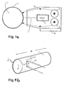
- Fig. 1 shows schematically a known device for performing an illustration of a printing form by thermal transfer
- Fig. 1a side view
- Fig. 1 b is a perspective view
- On a printing form cylinder 1 is one Printing form 2 as a printing plate or as a sleeve-shaped printing form (es but it would also be conceivable to image the surface of the cylinder itself).
- On Belt transport mechanism 3 carries a belt-shaped thermal transfer film 4 the width b close to or in contact with the surface of the printing form 2.
- a known and therefore not shown image information transmission unit comprises a printhead 5 which has at least one laser source includes one or more beams focused on the transfer belt 4.
- the Laser source 5, preferably an IR laser and the tape transport mechanism 3 are together on a traversing unit 6 in the preferred arrangement arranged, by means of this they over the width B of the printing form, which during any control with the cylinder 1 rotates, can be moved.
- the duration of laser imaging of a printing form is typically 1 to 2 Minutes.
- Fig. 2 shows schematically a graph of the image data oriented Control of the laser source, with a) the image data stream during imaging (first Step) and b) the image data-oriented control on the surface of the Show printing form (fix, second step).
- the Image data-oriented control of the surface of the printing form (fixing, second Step) in the reverse order to that which was controlled by the image in the first step Heating of the transfer film can be made. That the print head 5 (Fig. 1) traverses once on the printing form 2 along the width B of the Printing form from left to right.
- the Print head 5 After removing the transfer film 4 the Print head 5 once from right to left back to the starting position and controls the surface of the printing form in reverse order to the way there. This will optimize the path reached because the "idling" of the print head 5 in the initial position and so a distance B is avoided.
- both for the first step and the same laser source is used for the second step.
- the preferred combined training of the laser source as an imaging unit and as However, the fixing device does not preclude the use of different laser sources out.
- the polymer layer applied to the printing form is by means of the laser source 5 warmed briefly above the Tg temperature (glass transition temperature) of the polymer.
- the Heating takes place locally and for a limited time. This can cause damage of the "image-free" space are almost excluded.
- the spatial Limitation can be achieved by changing the intensity distribution to reach. Diffractive hybrid elements are ideally suited for this.
- the deletion process that follows the completed printing process Removing the image information from the surface of the printing form can be done in particularly advantageously also by means of a laser source be carried out in an image data-oriented manner by adjusting the power of the Laser beam is made so that the image information pixel by pixel from the Surface of the printing form can easily be burned away.
- a laser source is already described in DE 195 03 951 C2 several intensity levels can be switched, i.e. a corresponding Power adjustment, i.e. the radiance per unit area, i.e. the radiance can be set.
- training the device for one is also Realize thermal transfer such that the print head 5 is a first laser source for imaging the printing form, a second laser source with special adapted intensity distribution for the image data oriented heating of the Surface of the printing form 2 and another laser source with accordingly adjusted radiance to remove image information from the surface the printing form as a structural unit.
- the method according to the invention is said to be feasible in a printing press be, however, the invention is in no way on the imagewise coating of a Printing form limited within a printing press, but is suitable in principle also for the production of a printing form outside of a printing press.
- the print image carrier i.e. the printing form a seamless Printing form cylinder, a cylinder sleeve, or also a conventional, uncoated printing plate, which is clamped on a printing cylinder.
Description
Die Erfindung betrifft ein Verfahren zum reversiblen Bebildern einer Druckform durch bildmäßig gesteuerte Erwärmung einer Oberfläche mittels Thermotransfer gemäß dem Oberbegriff des Anspruchs 1.The invention relates to a method for reversibly imaging a printing form by image-controlled heating of a surface by means of thermal transfer according to the preamble of claim 1.
Bekannt sind Druckverfahren, bei dem eine Druckform vorzugsweise auf einem Druckformzylinder bildmäßig von einer Thermotransferfolie mit Thermotransfermaterial versehen wird. Die Übertragung des Transfermaterials wird vorzugsweise laserinduziert vorgenommen, wobei aber auch andere Energiequellen wie Heizelemente, -zeilen, -matrizen oder ähnliches denkbar wären. Die Druckform wird dann insbesondere für ein Offset-Verfahren mit Druckfarben eingefärbt, die Druckfarbe der farbführenden Bereiche wird gegebenenfalls über eine Gummiwalze auf das zu bedruckende Substrat übertragen.Printing processes are known in which a printing form is preferably on a Printing form cylinder with a thermal transfer film Thermal transfer material is provided. The transfer of the transfer material is preferably carried out laser-induced, but also others Energy sources such as heating elements, lines, matrices or the like are conceivable would. The printing form is then used in particular for an offset process Ink colors, the ink of the ink-guiding areas is optionally over a rubber roller on the substrate to be printed transfer.
Für einen raschen Wechsel der Druckmotive, insbesondere für Kleinauflagen, ist angestrebt, den Vorgang innerhalb der Druckmaschine zum einen rechnergesteuert und zum anderen ohne Wechsel beweglicher Teile auszuführen.For a quick change of print motifs, especially for short runs aspired to the process within the printing press on the one hand computer-controlled and secondly without changing moving parts.
Beispielsweise zeigt die DE 38 09 915 A1 ein solches Druckverfahren. Mittels einer Bildinformations-Übertragungseinheit wird innerhalb der Druckmaschine die Bildinformation in Form von farbannehmenden Flächenelementen auf die lipophobe Oberfläche der Druckform, bzw. des Druckformzylinders übertragen. Die Thermotransferfolie ist mit einer thermo- oder elektrothermosensitiven Beschichtung versehen, die oleophile, d.h. farbannehmende Eigenschaften hat. Die Bildinformations-Übertragungseinheit umfaßt einen Druckkopf, der eine Heizelementezeile, eine Elektrode, ein Energiestrahl oder jede ander wärmeerzeugende Einheit, insbesondere ein Laserdruckkopf sein kann. Zur Übertragung einer Bildinformation wird der Druckkopf über die entsprechenden Bildsignale so gesteuert, daß er bei jedem Bildpunkt Wärme und Druck auf die Thermotransferfolie einleitet und damit eine punktuelle Übertragung der Beschichtung der Folie auf die Oberfläche des Druckformzylinders bewirkt. Der Druckformzylinder rotiert dabei, der Druckkopf wird entsprechend traversiert, so daß von der Thermotransferfolie beispielsweise spiralförmig die Druckform auf dem Druckformzylinder bebildert werden kann.For example, DE 38 09 915 A1 shows such a printing process. through an image information transmission unit within the printing press Image information in the form of color-accepting surface elements on the transfer lipophobic surface of the printing form or the printing form cylinder. The thermal transfer foil is with a thermo or electrothermal sensitive Provide coating that oleophilic, i.e. has ink-accepting properties. The image information transfer unit includes a printhead which is one Row of heating elements, an electrode, an energy beam or any other heat generating unit, in particular a laser printhead. to The print head is transferred via the corresponding image information Image signals controlled so that he is at each pixel heat and pressure on the Thermal transfer film initiates and thus a selective transfer of Coating the film on the surface of the printing form cylinder causes. The Printing form cylinder rotates, the print head is traversed accordingly, see above that from the thermal transfer film, for example, spirally on the printing form the printing form cylinder can be illustrated.
Verfahren zum Bebildern einer Druckform mittels Thermotransfer, wobei eine Transferfolie zwischen der Druckform und einem Druckkopf durchgeführt wird und die Bebilderung der Oberfläche der Druckform durch punktuelle, d.h. bilddatenorientierte Ansteuerung und Übertragung der Beschichtung der Transferfolie vorgenommen wird, sind z.B. aus der US-A-5 395 729 oder der WO-A-98/08142 bekannt.Process for imaging a printing form by means of thermal transfer, one of which Transfer film is carried out between the printing form and a printhead and the Imaging of the surface of the printing form by selective, i.e. as image data Control and transfer of the coating of the transfer film is carried out, are e.g. known from US-A-5 395 729 or WO-A-98/08142.
Zur wiederholten bildmäßigen Beschichtung einer derartigen Druckform sind innerhalb der Druckmaschine Baugruppen, bestehend aus einer Zuführeinrichtung für eine Thermotransferfolie an den Druckformzylinder, einem mit der Rotationsbewegung des Druckformzylinders koordinierbaren Laserdruckkopf, sowie aus einer elektronisch gesteuerten Bildpunkte-Übertragungseinheit zur Aktivierung des Laserdruckkopfes und einem Element, das die bildmäßige Beschichtung von der Druckform wieder abheben kann, angeordnet. Der in der EP 0 698 488 B1 vorgestellte Gegenstand erfüllt diesen Bedarf. Wie die 196 24 441 C1 zeigt, kann das Element zur Abhebung der bildmäßigen Beschichtung, bzw. des Thermotransfermaterials von der Oberfläche der Druckform ein Hochdruckreiniger sein.For repeated imagewise coating of such a printing form Assemblies within the printing press, consisting of a feed device for a thermal transfer film to the printing form cylinder, one with the Rotational movement of the printing form cylinder coordinatable laser print head, and from an electronically controlled pixel transmission unit for Activation of the laser printhead and an element that the imagewise Coating can lift off the printing form, arranged. The Indian The subject presented in EP 0 698 488 B1 fulfills this need. Like the 196 24 441 C1 shows, the element for lifting off the imagewise coating, or the thermal transfer material from the surface of the printing form Be a pressure washer.
Die beim Gegenstand der EP 0 698 488 B1 verwendete bandförmige Thermotransferfolie zeichnet sich durch eine vergleichsweise dünne Beschichtung mit Thermotransfermaterial aus. Damit fällt die Bebilderungsschichtstärke auf dem Druckformzylinder dünn aus, so daß diese bildmäßige Beschichtung auch wieder leicht abgehoben werden kann, also der Druckformzylinder entsprechend der Reduzierung der Schichtstärke des Thermotransfermaterials leichter, bzw. schneller wieder gelöscht werden kann.The band-shaped used in the subject of EP 0 698 488 B1 Thermal transfer foil is characterized by a comparatively thin coating with thermal transfer material. The imaging layer thickness thus falls on the Printing form cylinder thin, so that this pictorial coating again can be easily lifted off, i.e. the printing form cylinder corresponding to the Reduction of the layer thickness of the thermal transfer material easier, or can be deleted more quickly.
Allerdings ist in der Fachwelt auch bekannt, daß die Auflagenbeständigkeit einer thermotransferbebilderten Druckform, also die gleichbleibende Druckqualität über die gesamte Anzahl der zu druckenden Exemplare eines bestimmten However, it is also known in the professional world that the durability of a thermotransfer-imaged printing form, so the consistent print quality over the total number of copies of a given to be printed
Druckproduktes, direkt von der Schichtdicke des Thermotransfermaterials abhängt. Wird diese Schichtdicke zugunsten der Auflagenbeständigkeit erhöht, handelt man sich jedoch Probleme beim Abheben der bildmäßigen Beschichtung der Druckform beim Löschen ein, was Farbschleier, bzw. Geisterbilder, also sogenanntes Tonen auf der Druckform, bzw. im Druckbild zur Folge hat.Print product, directly from the layer thickness of the thermal transfer material depends. If this layer thickness is increased in favor of the durability, however, there are problems with lifting the imagewise coating the printing form when deleting what color veil, or ghosting, so so-called toning on the printing form or in the printed image.
Es soll aber nicht nur sichergestellt sein, daß die bildmäßig beschichtete Druckform eine für eine möglichst hohe Auflage ausreichende Standzeit bei gleichbleibender Druckqualität bietet, sondern auch daß das bildmäßig übertragene Thermotransfermaterial auf der Druckform nach dem Druckvorgang in einfacher Weise umweltschonend und schnell entfernt werden kann, damit alsbald ein neuer Bebilderungs- und Druckvorgang beginnen kann.However, it should not only be ensured that the image is coated Print form a sufficient service life for the longest possible circulation offers consistent print quality, but also that the image transferred thermal transfer material on the printing form after the printing process can be removed quickly and easily in an environmentally friendly manner a new imaging and printing process can begin immediately.
Aus diesem Grunde hat man bereits versucht, einerseits bei dem vorbeschriebenen Druckverfahren zwar eine dünnschichtige Thermotransferfolie zu verwenden, aber dann eine Infrarot-Härtung der bildmäßigen Beschichtung auf der Druckform durchzuführen, so daß eine zusätzliche Aushärtung dieser Bebilderungsschicht erreicht und die Auflagenbeständigkeit erhöht wird. Bei dieser thermischen Nachbehandlung (Fixierung) wird das Polymer der Bebilderungsschicht durch Wärmeeintrag über die Glastemperatur erwärmt.For this reason, one has already tried, on the one hand, the a thin layer thermal transfer film to use, but then infrared curing the imagewise coating perform the printing form, so that additional curing of this Imaging layer reached and the print run resistance is increased. At this thermal aftertreatment (fixation) is the polymer of the Imaging layer heated by the introduction of heat above the glass temperature.
Dazu wird eine Infrarot-Bestrahlung der vom punktuell übertragenen Thermotransfermaterial auf der Druckform gebildeten Schicht durchgeführt, wodurch die Haftung auf der Oberfläche der Druckform im Vergleich zu unbestrahlten Bereichen auf der Druckform erhöht wird. Eine derartige IR-Bestrahlung umfaßt auch die durch Laser induzierte Wärmeeinbringung. Es hat sich jedoch gezeigt, daß diese Infrarot-Härtung (da großflächig durchgeführt) zu einer starken Aufheizung einzelner Bereiche der Druckform führt, insbesondere zu einer sujetabhängigen, ungleichmäßigen Erwärmung der Bebilderungsschicht auf der Druckform, d.h. daß Vollton-Bildbereiche stärker aufheizen als abgestufte Halbton-Bildbereiche. Im Extremfall bedeutet dies, daß die Eigenschaft einer verbesserten Auflagenbeständigkeit ungleichmäßig auf der Druckform verteilt ist und durch die sujetabhängige Wärmeausdehnung z.B. ein Verlust der Registerhaltigkeit auftritt oder daß für die Druckform insgesamt eben keine verbesserte Auflagenbeständigkeit erreicht wurde.For this purpose, an infrared radiation is transmitted from the point transmitted Thermal transfer material carried out on the layer formed on the printing form, whereby the adhesion to the surface of the printing form compared to unirradiated areas on the printing form is increased. Such IR radiation also includes laser-induced heat input. It has However, it has been shown that this infrared curing (since carried out over a large area) leads to a strong heating of individual areas of the printing form, in particular a subject-dependent, uneven heating of the imaging layer the printing form, i.e. spot areas heat up more than graded areas Halftone image areas. In extreme cases, this means that the property of a improved circulation resistance is distributed unevenly on the printing form and due to the subject-dependent thermal expansion e.g. a loss of Register accuracy occurs or that none for the printing form as a whole improved circulation resistance was achieved.
Es ist die Aufgabe der Erfindung, eine Druckform mittels eines Thermotransfermaterials reversibel so zu bebildern, daß eine hohe Auflage mit gleichbleibender Druckqualität sichergestellt wird, ohne die Schichtdicke des Thermotransfermaterials entprechend der gewünschten Auflage anpassen zu müssen und das bildmäßige Löschen der Druckform zu vereinfachen.It is the object of the invention to use a printing form Reversible images of thermal transfer material so that a high circulation with consistent print quality is ensured without the layer thickness of the Adjust thermal transfer material according to the desired edition need and to simplify the pictorial deletion of the printing form.
Erfindungsgemäß wird deshalb vorgeschlagen, in einem ersten Schritt eine an sich bekannte Bebilderung der Druckform durch punktuelle Ansteuerung, also bildmäßig gesteuerter Erwärmung des Thermotransfermaterials auf der Transferfolie, und Übertragung der Bildpunkte auf die Oberfläche der Druckform vorzunehemen, daraufhin die Transferfolie zwischen der Druckform und der Bildinformation-Übertragungseinheit zu entfemen und in einem zweiten Schritt eine bilddatenorientierte Ansteuerung, d.h. bildmäßig gesteuerten Erwärmung der Oberfläche der Druckform vorzunehmen, so daß die im ersten Schritt pixelartig übertragene Bildinformation auf der Druckform Pixel für Pixel ein zweites mal erwärmt wird. Nach dem Druckvorgang können die so fixierten Bildinformationen, d.h. die Polymerteile von der Druckform wieder entfernt werden.According to the invention, it is therefore proposed to start one in a first step well-known imaging of the printing form by selective control, so imagewise controlled heating of the thermal transfer material on the Transfer film, and transfer of the pixels on the surface of the printing form to carry out, then the transfer film between the printing form and the Image information transmission unit to remove and in a second step an image data-oriented control, i.e. imagewise controlled heating of the Make surface of the printing form, so that in the first step pixel-like transferred image information on the printing form pixel for pixel a second time is heated. After printing, the image information thus fixed, i.e. the polymer parts are removed from the printing form.
Dadurch daß eben ohne Zwischenschaltung der Transferfolie die bereits übertragene Bildinformation ein zweites mal, vorzugsweise von einem Laserdruckkopf angesteuert wird, wird die Bebilderungsenergie erhöht und die Bildpunkte härten besser aus, so daß die Auflagenbeständigkeit der Thermotransfermaterialschicht klar verbessert wird, ohne daß die Schichtdicke vergrößert werden muß. Because already without the interposition of the transfer film transmitted image information a second time, preferably from one Laser print head is driven, the imaging energy is increased and the Pixels harden better, so that the durability of the Thermal transfer material layer is clearly improved without the layer thickness must be enlarged.
Die vorzugsweise bandförmige Thermotransferfolie besteht bekanntlich aus einer Substratschicht, d.h. die Trägerfolie oder das Trägerband, aus einem möglichst transparenten, wärmebeständigen Kunststoff und darauf aufgetragen eine Donorschicht, d.h. die wärmeempfindliche übertragbare Schicht. Durch Einwirkung vorzugsweise eines Laserstrahls von der Rückseite des Thermotransferbands, d.h. von der unbeschichteten Seite, wird in der Donorschicht Wärme induziert, die zum Erweichen und schließlich zum Ablösen des Thermotransfermaterials führt, das auf die Druckform übertragen dort aufgrund der hohen Wärmekapazität des Druckformmaterials, z.B Metall, sofort abkühlt und anhaftet. Die Thermotransferfolie, insbesondere die Schicht des Thermotransfermaterials, weist dabei vorzugsweise eine Schichtdicke von etwa 0,5 bis 3 µm auf.As is known, the preferably ribbon-shaped thermal transfer film consists of a Substrate layer, i.e. the carrier film or the carrier tape, from one if possible transparent, heat-resistant plastic and applied one Donor layer, i.e. the heat sensitive transferable layer. By Exposure preferably to a laser beam from the back of the Thermal transfer ribbons, i.e. from the uncoated side, is in the Donor layer induces heat, which is used to soften and eventually detach of the thermal transfer material that is transferred to the printing form there due to the high thermal capacity of the printing plate material, e.g. metal, immediately cools and adheres. The thermal transfer film, in particular the layer of Thermal transfer material, preferably has a layer thickness of about 0.5 to 3 µm.
Fig. 1 zeigt schematisch eine an sich bekannte Vorrichtung zur Durchführung
einer Bebilderung einer Druckform durch Thermotransfer (Fig. 1a: Seitenansicht,
Fig. 1 b eine perspektivische Darstellung). Auf einem Druckformzylinder 1 ist eine
Druckform 2 als Druckplatte oder als hülsenförmige Druckform aufgebrach (es
wäre aber auch denkbar, die Oberfläche des Zylinders selbst zu bebildern). Ein
Bandtransportmechanismus 3 führt eine bandförmige Thermotransferfolie 4 mit
der Breite b nahe an, bzw. in Kontakt mit der Oberfläche der Druckform 2 vorbei.
Eine an sich bekannte und deshalb nicht gezeigte Bildinformation-Übertragungseinheit
umfaßt einen Druckkopf 5, der mindestens eine Laserquelle
beinhaltet, die einen oder mehrere Strahlen auf das Transferband 4 fokussiert. Die
Laserquelle 5, vorzugsweise ein IR-Laser und der Bandtransportmechanismus 3
sind in der bevorzugten Anordnung gemeinsam auf einer Traversiereinheit 6
angeordnet, mittels dieser sie über die Breite B der Druckform, die während
jeglicher Ansteuerung mit dem Zylinder 1 rotiert, bewegt werden können.Fig. 1 shows schematically a known device for performing
an illustration of a printing form by thermal transfer (Fig. 1a: side view,
Fig. 1 b is a perspective view). On a printing form cylinder 1 is one
Die Dauer einer Laserbebilderung einer Druckform beträgt typischerweise 1 bis 2 Minuten. The duration of laser imaging of a printing form is typically 1 to 2 Minutes.
Vorzugsweise wird nun für den zweiten Schritt, für die sozusagen zweite mit der ersten identischen Bebilderung der Oberfläche der Druckform, allerdings ohne Zwischenschaltung der Transferfolie, die gleiche Zeitdauer wie für den ersten Schritt aufgewendet, so daß die Bebilderungszeit quasi verdoppelt wird.Now, for the second step, for the second step, so to speak, with the first identical illustration of the surface of the printing form, but without Interposition of the transfer film, the same duration as for the first Step spent so that the imaging time is almost doubled.
Dabei gibt es zwei Vorgehensmöglichkeiten. Einmal kann die bilddatenorientierte
Ansteuerung der Oberfläche der Druckform (zweiter Schritt) identisch mit der im
ersten Schritt bildmäßig gesteuerten Erwärmung der Transferfolie vorgenommen
werden. Fig. 2 zeigt schematisch einen Graph der bilddatenorientierten
Ansteuerung der Laserquelle, wobei a) den Bilddatenstrom beim Bebildern (erster
Schritt) und b) die bilddatenorientierte Ansteuerung auf der Oberfläche der
Druckform (Fixieren, zweiter Schritt) zeigen. Andererseits kann die
bilddatenorientierte Ansteuerung der Oberfläche der Druckform (Fixieren, zweiter
Schritt) in umgekehrter Reihenfolge zu der im ersten Schritt bildmäßig gesteuerten
Erwärmung der Transferfolie vorgenommen werden. D.h. der Druckkopf 5 (Fig. 1)
traversiert beim Bebildern der Druckform 2 einmal längs der Breite B der
Druckform von links nach rechts. Nach dem Entfernen der Transferfolie 4 fährt der
Druckkopf 5 einmal von recht nach links zurück in die Anfangsstellung und steuert
dabei auf dem Rückweg bilddatenorientiert die Oberfläche der Druckform in
umgekehrter Reihenfolge zum Hinweg an. Dadurch wird eine Wegoptimierung
erreicht, da das "Leerlaufen" des Druckkopfes 5 in die Anfangsstellung und so
eine Wegstrecke B vermieden wird.There are two ways of doing this. Once the image data oriented
Control of the surface of the printing form (second step) identical to that in the
the first step is image-controlled heating of the transfer film
become. Fig. 2 shows schematically a graph of the image data oriented
Control of the laser source, with a) the image data stream during imaging (first
Step) and b) the image data-oriented control on the surface of the
Show printing form (fix, second step). On the other hand, the
Image data-oriented control of the surface of the printing form (fixing, second
Step) in the reverse order to that which was controlled by the image in the first step
Heating of the transfer film can be made. That the print head 5 (Fig. 1)
traverses once on the
In bevorzugter Weise ist vorgesehen, daß sowohl für den ersten Schritt als auch für den zweiten Schritt dieselbe Laserquelle verwendet wird. Die bevorzugte kombinierte Ausbildung der Laserquelle als Bebilderungseinheit und als Fixiervorrichtung schließt jedoch den Einsatz verschiedener Laserquellen nicht aus.It is preferably provided that both for the first step and the same laser source is used for the second step. The preferred combined training of the laser source as an imaging unit and as However, the fixing device does not preclude the use of different laser sources out.
Die auf die Druckform aufgebrachte Polymerschicht wird mittels der Laserquelle 5
kurzzeitig über die Tg-Temperatur (Glastemperatur) des Polymers erwärmt. Die
Erwärmung erfolgt lokal und zeitlich eng begrenzt. Damit kann eine Schädigung
des "bildfreien" Raums nahezu ausgeschlossen werden. Im Gegensatz dazu kann
bei einer flächigen Erwärmung/Bestrahlung, wie sie bisher durchgeführt wurde, es
zu einer Störung im Farb-Wasser-Gleichgewicht führen. Die räumliche
Begrenzung kann man durch gezielte Veränderung der Intensitätsverteilung
erreichen. Dazu sind diffraktive Hybridelemente bestens geeignet.The polymer layer applied to the printing form is by means of the
Der sich dem abgeschlossenen Druckvorgang anschließende Löschvorgang zum Entfernen der Bildinformation von der Oberfläche der Druckform kann in besonders vorteilhafter Weise ebenfalls mittels einer Laserquelle ebenfalls bilddatenorientiert durchgeführt werden, indem eine Leistungsjustage des Laserstrahls so vorgenommen wird, daß die Bildinformation Pixel für Pixel von der Oberfläche der Druckform einfach weggebrannt werden kann.The deletion process that follows the completed printing process Removing the image information from the surface of the printing form can be done in particularly advantageously also by means of a laser source be carried out in an image data-oriented manner by adjusting the power of the Laser beam is made so that the image information pixel by pixel from the Surface of the printing form can easily be burned away.
Aus der DE 195 03 951 C2 ist bereits eine Laserquelle beschrieben, die in mehreren Intensitätsstufen geschaltet werden kann, d.h. eine entsprechende Leistungsjustage, d.h. die Strahlstärke pro Flächeneinheit, also die Strahldichte eingestellt werden kannn.A laser source is already described in DE 195 03 951 C2 several intensity levels can be switched, i.e. a corresponding Power adjustment, i.e. the radiance per unit area, i.e. the radiance can be set.
Damit ist auch für die Baueinheit des Druckkopfes mit Laserquelle für Bebilderung und Fixieren die Möglichkeit gegeben, auch den Löschvorgang zu umfassen, also eine Laserquelle im Druckkopf erstens zum Bebildern, zweitens zum Fixieren der Bildelemente auf der Druckform und drittens zum Löschen der Bildinformation zu verwenden.This is also for the structural unit of the printhead with laser source for imaging and fixing the possibility to include the deletion process, so a laser source in the print head first for imaging, second for fixing the Picture elements on the printing form and third to delete the picture information use.
Selbstverständlich ist aber auch eine Ausbildung der Vorrichtung für einen
Thermotransfer derart zu realisieren, daß der Druckkopf 5 eine erste Laserquelle
für die Bebilderung der Druckform, eine zweite Laserquelle mit speziell
angepaßter Intensitätsverteilung für die bilddatenorientierte Erwärmung der
Oberfläche der Druckform 2 und eine weitere Laserquelle mit entsprechend
angepaßter Strahldichte zum Entfernen der Bildinformation von der Oberfläche
der Druckform als Baueinheit umfaßt.Of course, training the device for one is also
Realize thermal transfer such that the
Das erfindungsgemäße Verfahren soll zwar in einer Druckmaschine durchführbar sein, die Erfindung ist jedoch keinesfalls auf die bildmäßige Beschichtung einer Druckform innerhalb einer Druckmaschine beschränkt, sondern eignet sich prinzipiell auch zur Herstellung einer Druckform außerhalb einer Druckmaschine. Dabei kann der Druckbildträger, d.h. die Druckform ein nahtloser Druckformzylinder, eine Zylinderhülse, oder auch eine konventionelle, unbeschichtete Druckplatte, die auf einen Druckzylinder aufgespannt ist, sein.The method according to the invention is said to be feasible in a printing press be, however, the invention is in no way on the imagewise coating of a Printing form limited within a printing press, but is suitable in principle also for the production of a printing form outside of a printing press. The print image carrier, i.e. the printing form a seamless Printing form cylinder, a cylinder sleeve, or also a conventional, uncoated printing plate, which is clamped on a printing cylinder.
Claims (10)
- A process for reversibly imaging a forme by means of thermal transfer, wherein a transfer foil is passed through between the forme and an image-information transfer unit comprising a print head, in a first step the image information is undertaken in the form of an imaging of the surface of the forme by selective, i.e. image-data-oriented, control and transfer of the coating of the transfer foil, and thereupon the transfer foil between the forme and the image-information transfer unit is removed, characterised in that in a second step an image-data-oriented control of the surface of the forme is undertaken, so that the image points on the forme which were transferred in the first step are heated once again and can be removed after the printing operation.
- A process according to Claim 1, characterised in that the image-data-oriented control of the surface of the forme (second step) is undertaken in a manner identical with the heating of the transfer foil which is controlled in image-specific manner in the first step.
- A process according to Claim 1, characterised in that the image-data-oriented control of the surface of the forme (second step) is undertaken in reverse sequence in relation to the heating of the transfer foil which is controlled in image-specific manner in the first step.
- A process according to Claims 1 to 3, characterised in that the same period of time is expended for the second step as for the first step.
- A process according to Claim 1, characterised in that a laser source is used by way of print head for the image-data-oriented heating both of the transfer foil (first step) and of the forme (second step).
- A process according to Claim 1, characterised in that the erasing operation for the purpose of removing the image information from the surface of the forme by means of a laser source is likewise carried out in image-data-oriented manner by a power adjustment of the laser beam being undertaken in such a way that the image information can be burnt away from the surface of the forme.
- A process according to Claim 1, characterised in that a common laser source is used for both the first step and the second step.
- A process according to Claim 7, characterised in that the common laser source is also used for the erasing operation for the purpose of removing the image information from the surface of the forme.
- A device for implementing the A process according to Claim 1, which comprises assemblies consisting of a unit for feeding a thermal-transfer foil onto the forme, an image-information transfer unit comprising a print head, and an element for removing the image information from the surface of the forme, characterised in that the print head exhibits at least one laser source, by means of which the imaging of the forme (first step), the image-data-oriented heating of the surface of the forme (second step, fixing) and the removal of the image information from the surface of the forme (erasing) are capable of being carried out.
- A device according to Claim 9, characterised in that the print head comprises, as a modular unit, a first laser source for the imaging of the forme, a second laser source with specially adapted intensity distribution for the image-data-oriented heating of the surface of the forme, and an additional laser source with appropriately adapted radiance for the purpose of removing the image information from the surface of the forme.
Applications Claiming Priority (2)
| Application Number | Priority Date | Filing Date | Title |
|---|---|---|---|
| DE19939240 | 1999-08-18 | ||
| DE19939240A DE19939240C2 (en) | 1999-08-18 | 1999-08-18 | Method and device for reversibly imaging a printing form |
Publications (3)
| Publication Number | Publication Date |
|---|---|
| EP1077129A2 EP1077129A2 (en) | 2001-02-21 |
| EP1077129A3 EP1077129A3 (en) | 2001-03-07 |
| EP1077129B1 true EP1077129B1 (en) | 2003-12-03 |
Family
ID=7918851
Family Applications (1)
| Application Number | Title | Priority Date | Filing Date |
|---|---|---|---|
| EP00116981A Expired - Lifetime EP1077129B1 (en) | 1999-08-18 | 2000-08-08 | Process and apparatus for reversibly imaging a printing forme |
Country Status (5)
| Country | Link |
|---|---|
| US (1) | US6424366B1 (en) |
| EP (1) | EP1077129B1 (en) |
| JP (1) | JP3323186B2 (en) |
| CA (1) | CA2316429C (en) |
| DE (2) | DE19939240C2 (en) |
Families Citing this family (13)
| Publication number | Priority date | Publication date | Assignee | Title |
|---|---|---|---|---|
| DE10063819B4 (en) * | 2000-12-21 | 2006-02-02 | Man Roland Druckmaschinen Ag | Mask production for the production of a printing form |
| DE10121827B4 (en) | 2001-05-04 | 2005-12-22 | Man Roland Druckmaschinen Ag | Printing unit with reversible imaging and digital conversion |
| JP4262423B2 (en) * | 2001-07-03 | 2009-05-13 | 富士フイルム株式会社 | Image recording method and image recording apparatus |
| US6610458B2 (en) * | 2001-07-23 | 2003-08-26 | Kodak Polychrome Graphics Llc | Method and system for direct-to-press imaging |
| JP2005319782A (en) * | 2004-05-05 | 2005-11-17 | Man Roland Druckmas Ag | Method and device for manufacturing printing plate |
| DE102004022087A1 (en) * | 2004-05-05 | 2005-12-01 | Man Roland Druckmaschinen Ag | Method and device for the production of printing plates |
| DE102004051262A1 (en) * | 2004-10-21 | 2006-04-27 | Man Roland Druckmaschinen Ag | Offset printing machine for printing wall paper, has picturization mechanism picturizing re-recordable and erasable offset printing form that has smooth surface, where entire surface of form has defined roughness aligned to offset printing |
| DE102004053832A1 (en) * | 2004-11-04 | 2006-05-11 | Man Roland Druckmaschinen Ag | Erasable printing plate comprises an imaging layer containing magnetic or magnetizable nanoparticles |
| DE102005028817A1 (en) * | 2005-06-22 | 2007-01-11 | Man Roland Druckmaschinen Ag | Process for the production of printing plates |
| DE102005046863A1 (en) * | 2005-09-30 | 2007-06-14 | Man Roland Druckmaschinen Ag | printing form |
| DE102006052380B4 (en) * | 2006-11-07 | 2013-04-25 | Mühlbauer Ag | Device and method for introducing information into a data carrier |
| DE102007007183A1 (en) * | 2007-02-14 | 2008-08-21 | Man Roland Druckmaschinen Ag | Process for the production of printing plates |
| US9878531B2 (en) | 2013-12-19 | 2018-01-30 | Goss International Americas, Inc. | Reimageable and reusable printing sleeve for a variable cutoff printing press |
Family Cites Families (13)
| Publication number | Priority date | Publication date | Assignee | Title |
|---|---|---|---|---|
| US3964389A (en) * | 1974-01-17 | 1976-06-22 | Scott Paper Company | Printing plate by laser transfer |
| JPS59201037A (en) * | 1983-04-30 | 1984-11-14 | Canon Inc | Copying device with variable power |
| DE3809915A1 (en) * | 1988-03-24 | 1989-10-05 | Man Technologie Gmbh | Method for transferring printing images in lithoprinting |
| US5129321A (en) * | 1991-07-08 | 1992-07-14 | Rockwell International Corporation | Direct-to-press imaging system for use in lithographic printing |
| JPH06138793A (en) * | 1992-08-25 | 1994-05-20 | Ricoh Co Ltd | Fixing device |
| JPH0671936A (en) * | 1992-08-26 | 1994-03-15 | Sony Corp | Printing device and laser diode driving device |
| US5395729A (en) * | 1993-04-30 | 1995-03-07 | E. I. Du Pont De Nemours And Company | Laser-induced thermal transfer process |
| DE4426012C2 (en) * | 1994-07-22 | 1998-05-20 | Roland Man Druckmasch | Erasable printing form, its use and methods for erasing and regenerating the printing form |
| DE4430555C1 (en) * | 1994-08-27 | 1996-04-04 | Roland Man Druckmasch | Method and device for producing a printing form |
| DE19503951C2 (en) * | 1995-02-07 | 1998-04-09 | Roland Man Druckmasch | Method and device for gravure printing |
| DE19624441C1 (en) * | 1996-06-19 | 1997-12-04 | Roland Man Druckmasch | Method and device for gravure printing using an erasable gravure form |
| GB9617415D0 (en) * | 1996-08-20 | 1996-10-02 | Minnesota Mining & Mfg | Production of colour proofs and printing plates |
| EP0838729B1 (en) * | 1996-10-23 | 2003-05-21 | Mitsubishi Chemical Corporation | Electrophotographic copying method and electrophotographic copying machine used in the method |
-
1999
- 1999-08-18 DE DE19939240A patent/DE19939240C2/en not_active Expired - Fee Related
-
2000
- 2000-08-08 EP EP00116981A patent/EP1077129B1/en not_active Expired - Lifetime
- 2000-08-08 DE DE50004626T patent/DE50004626D1/en not_active Expired - Lifetime
- 2000-08-15 JP JP2000246482A patent/JP3323186B2/en not_active Expired - Fee Related
- 2000-08-18 CA CA002316429A patent/CA2316429C/en not_active Expired - Fee Related
- 2000-08-18 US US09/641,457 patent/US6424366B1/en not_active Expired - Fee Related
Also Published As
| Publication number | Publication date |
|---|---|
| DE19939240C2 (en) | 2002-09-26 |
| US6424366B1 (en) | 2002-07-23 |
| EP1077129A3 (en) | 2001-03-07 |
| JP3323186B2 (en) | 2002-09-09 |
| CA2316429A1 (en) | 2001-02-18 |
| DE19939240A1 (en) | 2001-03-22 |
| EP1077129A2 (en) | 2001-02-21 |
| JP2001080025A (en) | 2001-03-27 |
| DE50004626D1 (en) | 2004-01-15 |
| CA2316429C (en) | 2004-05-18 |
Similar Documents
| Publication | Publication Date | Title |
|---|---|---|
| EP1077129B1 (en) | Process and apparatus for reversibly imaging a printing forme | |
| EP0759582B1 (en) | Method for ink transfer and device and machines for carrying out said method | |
| DE2111561C2 (en) | Process for producing an impression and use of a tellurium-containing semiconductor layer for offset printing | |
| DE3917844C1 (en) | ||
| DE3248178A1 (en) | IMAGE COATING OF PRINTING FORMS FOR FLAT PRINTING | |
| EP1473154A2 (en) | Printing method and printing machine | |
| EP0264604A2 (en) | Lithographic-printing plate | |
| EP1151857B1 (en) | Controlled imaging formation and erasure on a metallic titanium printing form | |
| DE10360108A1 (en) | Printing plate, for the printing cylinder of an offset printing press has a surface of a shape memory material which is subjected to two different temperatures to give an erasure for repeated use | |
| DE69727126T2 (en) | IMAGE GENERATING APPARATUS FOR EXPOSURE AND PRINTING ELEMENT FOR IT | |
| DE3415827C2 (en) | ||
| DE3837898C2 (en) | ||
| DE3924848C1 (en) | ||
| EP0368180B1 (en) | Process for the production of images in a printing cylinder | |
| DE60202903T2 (en) | A method of making a decorative heat-sensitive transfer sheet on a flexible support system | |
| DE4341567C2 (en) | Method and device for reversibly describing a printing form support within an offset printing machine | |
| DE3814071C2 (en) | ||
| DE19654018A1 (en) | Method and device for generating a pressure distribution | |
| DE10121827A1 (en) | Printing unit with reversible imaging and digital conversion | |
| DE4119111A1 (en) | Prodn. of printing forme for offset work - involves producing droplets of oleophile, water-resistant medium with nozzles connected to reservoir and conveyed to parts of hydrophilic cylinder surface | |
| DE102008007228B4 (en) | Method and device for generating at least one print image on an image carrier | |
| EP0412179A1 (en) | Inking device for a thermal transfer printer | |
| EP2090429B1 (en) | Imaging of an offset printing plate | |
| CH662787A5 (en) | Method and device for producing a print on an object, for example a key body | |
| EP0746470B1 (en) | Thermotransfer printing device for transferring an image to a substrate |
Legal Events
| Date | Code | Title | Description |
|---|---|---|---|
| PUAI | Public reference made under article 153(3) epc to a published international application that has entered the european phase |
Free format text: ORIGINAL CODE: 0009012 |
|
| PUAL | Search report despatched |
Free format text: ORIGINAL CODE: 0009013 |
|
| AK | Designated contracting states |
Kind code of ref document: A2 Designated state(s): CH DE FR GB LI |
|
| AX | Request for extension of the european patent |
Free format text: AL;LT;LV;MK;RO;SI |
|
| AK | Designated contracting states |
Kind code of ref document: A3 Designated state(s): AT BE CH CY DE DK ES FI FR GB GR IE IT LI LU MC NL PT SE |
|
| AX | Request for extension of the european patent |
Free format text: AL;LT;LV;MK;RO;SI |
|
| RIC1 | Information provided on ipc code assigned before grant |
Free format text: 7B 41C 1/10 A, 7B 41N 3/00 B |
|
| 17P | Request for examination filed |
Effective date: 20010802 |
|
| AKX | Designation fees paid |
Free format text: CH DE FR GB LI |
|
| GRAH | Despatch of communication of intention to grant a patent |
Free format text: ORIGINAL CODE: EPIDOS IGRA |
|
| GRAS | Grant fee paid |
Free format text: ORIGINAL CODE: EPIDOSNIGR3 |
|
| GRAA | (expected) grant |
Free format text: ORIGINAL CODE: 0009210 |
|
| AK | Designated contracting states |
Kind code of ref document: B1 Designated state(s): CH DE FR GB LI |
|
| REG | Reference to a national code |
Ref country code: GB Ref legal event code: FG4D Free format text: NOT ENGLISH |
|
| REG | Reference to a national code |
Ref country code: CH Ref legal event code: NV Representative=s name: DR. R.C. SALGO EUROPEAN PATENT ATTORNEY Ref country code: CH Ref legal event code: EP |
|
| REF | Corresponds to: |
Ref document number: 50004626 Country of ref document: DE Date of ref document: 20040115 Kind code of ref document: P |
|
| GBT | Gb: translation of ep patent filed (gb section 77(6)(a)/1977) |
Effective date: 20040317 |
|
| ET | Fr: translation filed | ||
| PLBE | No opposition filed within time limit |
Free format text: ORIGINAL CODE: 0009261 |
|
| STAA | Information on the status of an ep patent application or granted ep patent |
Free format text: STATUS: NO OPPOSITION FILED WITHIN TIME LIMIT |
|
| 26N | No opposition filed |
Effective date: 20040906 |
|
| REG | Reference to a national code |
Ref country code: CH Ref legal event code: PFA Owner name: MAN ROLAND DRUCKMASCHINEN AG Free format text: MAN ROLAND DRUCKMASCHINEN AG#POSTFACH 10 12 64#63012 OFFENBACH (DE) -TRANSFER TO- MAN ROLAND DRUCKMASCHINEN AG#POSTFACH 10 12 64#63012 OFFENBACH (DE) |
|
| REG | Reference to a national code |
Ref country code: CH Ref legal event code: PFA Owner name: MANROLAND AG Free format text: MAN ROLAND DRUCKMASCHINEN AG#POSTFACH 10 12 64#63012 OFFENBACH (DE) -TRANSFER TO- MANROLAND AG#MUEHLHEIMER STRA?E 341#63075 OFFENBACH (DE) |
|
| PGFP | Annual fee paid to national office [announced via postgrant information from national office to epo] |
Ref country code: CH Payment date: 20080814 Year of fee payment: 9 |
|
| PGFP | Annual fee paid to national office [announced via postgrant information from national office to epo] |
Ref country code: GB Payment date: 20080821 Year of fee payment: 9 |
|
| REG | Reference to a national code |
Ref country code: FR Ref legal event code: CD |
|
| REG | Reference to a national code |
Ref country code: CH Ref legal event code: PL |
|
| GBPC | Gb: european patent ceased through non-payment of renewal fee |
Effective date: 20090808 |
|
| PG25 | Lapsed in a contracting state [announced via postgrant information from national office to epo] |
Ref country code: CH Free format text: LAPSE BECAUSE OF NON-PAYMENT OF DUE FEES Effective date: 20090831 Ref country code: LI Free format text: LAPSE BECAUSE OF NON-PAYMENT OF DUE FEES Effective date: 20090831 |
|
| PG25 | Lapsed in a contracting state [announced via postgrant information from national office to epo] |
Ref country code: GB Free format text: LAPSE BECAUSE OF NON-PAYMENT OF DUE FEES Effective date: 20090808 |
|
| PGFP | Annual fee paid to national office [announced via postgrant information from national office to epo] |
Ref country code: FR Payment date: 20100901 Year of fee payment: 11 Ref country code: DE Payment date: 20100823 Year of fee payment: 11 |
|
| REG | Reference to a national code |
Ref country code: FR Ref legal event code: ST Effective date: 20120430 |
|
| REG | Reference to a national code |
Ref country code: DE Ref legal event code: R119 Ref document number: 50004626 Country of ref document: DE Effective date: 20120301 |
|
| PG25 | Lapsed in a contracting state [announced via postgrant information from national office to epo] |
Ref country code: FR Free format text: LAPSE BECAUSE OF NON-PAYMENT OF DUE FEES Effective date: 20110831 |
|
| PG25 | Lapsed in a contracting state [announced via postgrant information from national office to epo] |
Ref country code: DE Free format text: LAPSE BECAUSE OF NON-PAYMENT OF DUE FEES Effective date: 20120301 |