EP1077123A2 - Injection apparatus and method of controlling the same - Google Patents
Injection apparatus and method of controlling the same Download PDFInfo
- Publication number
- EP1077123A2 EP1077123A2 EP00115767A EP00115767A EP1077123A2 EP 1077123 A2 EP1077123 A2 EP 1077123A2 EP 00115767 A EP00115767 A EP 00115767A EP 00115767 A EP00115767 A EP 00115767A EP 1077123 A2 EP1077123 A2 EP 1077123A2
- Authority
- EP
- European Patent Office
- Prior art keywords
- screw
- speed
- flight
- injection
- resin
- Prior art date
- Legal status (The legal status is an assumption and is not a legal conclusion. Google has not performed a legal analysis and makes no representation as to the accuracy of the status listed.)
- Granted
Links
Images


Classifications
-
- B—PERFORMING OPERATIONS; TRANSPORTING
- B29—WORKING OF PLASTICS; WORKING OF SUBSTANCES IN A PLASTIC STATE IN GENERAL
- B29C—SHAPING OR JOINING OF PLASTICS; SHAPING OF MATERIAL IN A PLASTIC STATE, NOT OTHERWISE PROVIDED FOR; AFTER-TREATMENT OF THE SHAPED PRODUCTS, e.g. REPAIRING
- B29C45/00—Injection moulding, i.e. forcing the required volume of moulding material through a nozzle into a closed mould; Apparatus therefor
- B29C45/17—Component parts, details or accessories; Auxiliary operations
- B29C45/76—Measuring, controlling or regulating
-
- B—PERFORMING OPERATIONS; TRANSPORTING
- B29—WORKING OF PLASTICS; WORKING OF SUBSTANCES IN A PLASTIC STATE IN GENERAL
- B29C—SHAPING OR JOINING OF PLASTICS; SHAPING OF MATERIAL IN A PLASTIC STATE, NOT OTHERWISE PROVIDED FOR; AFTER-TREATMENT OF THE SHAPED PRODUCTS, e.g. REPAIRING
- B29C45/00—Injection moulding, i.e. forcing the required volume of moulding material through a nozzle into a closed mould; Apparatus therefor
- B29C45/17—Component parts, details or accessories; Auxiliary operations
- B29C45/46—Means for plasticising or homogenising the moulding material or forcing it into the mould
- B29C45/47—Means for plasticising or homogenising the moulding material or forcing it into the mould using screws
- B29C45/50—Axially movable screw
-
- B—PERFORMING OPERATIONS; TRANSPORTING
- B29—WORKING OF PLASTICS; WORKING OF SUBSTANCES IN A PLASTIC STATE IN GENERAL
- B29C—SHAPING OR JOINING OF PLASTICS; SHAPING OF MATERIAL IN A PLASTIC STATE, NOT OTHERWISE PROVIDED FOR; AFTER-TREATMENT OF THE SHAPED PRODUCTS, e.g. REPAIRING
- B29C45/00—Injection moulding, i.e. forcing the required volume of moulding material through a nozzle into a closed mould; Apparatus therefor
- B29C45/17—Component parts, details or accessories; Auxiliary operations
- B29C2045/1784—Component parts, details or accessories not otherwise provided for; Auxiliary operations not otherwise provided for
- B29C2045/1792—Machine parts driven by an electric motor, e.g. electric servomotor
-
- B—PERFORMING OPERATIONS; TRANSPORTING
- B29—WORKING OF PLASTICS; WORKING OF SUBSTANCES IN A PLASTIC STATE IN GENERAL
- B29C—SHAPING OR JOINING OF PLASTICS; SHAPING OF MATERIAL IN A PLASTIC STATE, NOT OTHERWISE PROVIDED FOR; AFTER-TREATMENT OF THE SHAPED PRODUCTS, e.g. REPAIRING
- B29C2945/00—Indexing scheme relating to injection moulding, i.e. forcing the required volume of moulding material through a nozzle into a closed mould
- B29C2945/76—Measuring, controlling or regulating
- B29C2945/76003—Measured parameter
- B29C2945/76006—Pressure
-
- B—PERFORMING OPERATIONS; TRANSPORTING
- B29—WORKING OF PLASTICS; WORKING OF SUBSTANCES IN A PLASTIC STATE IN GENERAL
- B29C—SHAPING OR JOINING OF PLASTICS; SHAPING OF MATERIAL IN A PLASTIC STATE, NOT OTHERWISE PROVIDED FOR; AFTER-TREATMENT OF THE SHAPED PRODUCTS, e.g. REPAIRING
- B29C2945/00—Indexing scheme relating to injection moulding, i.e. forcing the required volume of moulding material through a nozzle into a closed mould
- B29C2945/76—Measuring, controlling or regulating
- B29C2945/76003—Measured parameter
- B29C2945/76013—Force
-
- B—PERFORMING OPERATIONS; TRANSPORTING
- B29—WORKING OF PLASTICS; WORKING OF SUBSTANCES IN A PLASTIC STATE IN GENERAL
- B29C—SHAPING OR JOINING OF PLASTICS; SHAPING OF MATERIAL IN A PLASTIC STATE, NOT OTHERWISE PROVIDED FOR; AFTER-TREATMENT OF THE SHAPED PRODUCTS, e.g. REPAIRING
- B29C2945/00—Indexing scheme relating to injection moulding, i.e. forcing the required volume of moulding material through a nozzle into a closed mould
- B29C2945/76—Measuring, controlling or regulating
- B29C2945/76003—Measured parameter
- B29C2945/76083—Position
-
- B—PERFORMING OPERATIONS; TRANSPORTING
- B29—WORKING OF PLASTICS; WORKING OF SUBSTANCES IN A PLASTIC STATE IN GENERAL
- B29C—SHAPING OR JOINING OF PLASTICS; SHAPING OF MATERIAL IN A PLASTIC STATE, NOT OTHERWISE PROVIDED FOR; AFTER-TREATMENT OF THE SHAPED PRODUCTS, e.g. REPAIRING
- B29C2945/00—Indexing scheme relating to injection moulding, i.e. forcing the required volume of moulding material through a nozzle into a closed mould
- B29C2945/76—Measuring, controlling or regulating
- B29C2945/76003—Measured parameter
- B29C2945/7611—Velocity
- B29C2945/76113—Velocity linear movement
-
- B—PERFORMING OPERATIONS; TRANSPORTING
- B29—WORKING OF PLASTICS; WORKING OF SUBSTANCES IN A PLASTIC STATE IN GENERAL
- B29C—SHAPING OR JOINING OF PLASTICS; SHAPING OF MATERIAL IN A PLASTIC STATE, NOT OTHERWISE PROVIDED FOR; AFTER-TREATMENT OF THE SHAPED PRODUCTS, e.g. REPAIRING
- B29C2945/00—Indexing scheme relating to injection moulding, i.e. forcing the required volume of moulding material through a nozzle into a closed mould
- B29C2945/76—Measuring, controlling or regulating
- B29C2945/76177—Location of measurement
- B29C2945/7618—Injection unit
- B29C2945/76187—Injection unit screw
-
- B—PERFORMING OPERATIONS; TRANSPORTING
- B29—WORKING OF PLASTICS; WORKING OF SUBSTANCES IN A PLASTIC STATE IN GENERAL
- B29C—SHAPING OR JOINING OF PLASTICS; SHAPING OF MATERIAL IN A PLASTIC STATE, NOT OTHERWISE PROVIDED FOR; AFTER-TREATMENT OF THE SHAPED PRODUCTS, e.g. REPAIRING
- B29C2945/00—Indexing scheme relating to injection moulding, i.e. forcing the required volume of moulding material through a nozzle into a closed mould
- B29C2945/76—Measuring, controlling or regulating
- B29C2945/76177—Location of measurement
- B29C2945/76287—Moulding material
-
- B—PERFORMING OPERATIONS; TRANSPORTING
- B29—WORKING OF PLASTICS; WORKING OF SUBSTANCES IN A PLASTIC STATE IN GENERAL
- B29C—SHAPING OR JOINING OF PLASTICS; SHAPING OF MATERIAL IN A PLASTIC STATE, NOT OTHERWISE PROVIDED FOR; AFTER-TREATMENT OF THE SHAPED PRODUCTS, e.g. REPAIRING
- B29C2945/00—Indexing scheme relating to injection moulding, i.e. forcing the required volume of moulding material through a nozzle into a closed mould
- B29C2945/76—Measuring, controlling or regulating
- B29C2945/76344—Phase or stage of measurement
- B29C2945/76381—Injection
-
- B—PERFORMING OPERATIONS; TRANSPORTING
- B29—WORKING OF PLASTICS; WORKING OF SUBSTANCES IN A PLASTIC STATE IN GENERAL
- B29C—SHAPING OR JOINING OF PLASTICS; SHAPING OF MATERIAL IN A PLASTIC STATE, NOT OTHERWISE PROVIDED FOR; AFTER-TREATMENT OF THE SHAPED PRODUCTS, e.g. REPAIRING
- B29C2945/00—Indexing scheme relating to injection moulding, i.e. forcing the required volume of moulding material through a nozzle into a closed mould
- B29C2945/76—Measuring, controlling or regulating
- B29C2945/76494—Controlled parameter
- B29C2945/76498—Pressure
-
- B—PERFORMING OPERATIONS; TRANSPORTING
- B29—WORKING OF PLASTICS; WORKING OF SUBSTANCES IN A PLASTIC STATE IN GENERAL
- B29C—SHAPING OR JOINING OF PLASTICS; SHAPING OF MATERIAL IN A PLASTIC STATE, NOT OTHERWISE PROVIDED FOR; AFTER-TREATMENT OF THE SHAPED PRODUCTS, e.g. REPAIRING
- B29C2945/00—Indexing scheme relating to injection moulding, i.e. forcing the required volume of moulding material through a nozzle into a closed mould
- B29C2945/76—Measuring, controlling or regulating
- B29C2945/76494—Controlled parameter
- B29C2945/76595—Velocity
- B29C2945/76598—Velocity linear movement
-
- B—PERFORMING OPERATIONS; TRANSPORTING
- B29—WORKING OF PLASTICS; WORKING OF SUBSTANCES IN A PLASTIC STATE IN GENERAL
- B29C—SHAPING OR JOINING OF PLASTICS; SHAPING OF MATERIAL IN A PLASTIC STATE, NOT OTHERWISE PROVIDED FOR; AFTER-TREATMENT OF THE SHAPED PRODUCTS, e.g. REPAIRING
- B29C2945/00—Indexing scheme relating to injection moulding, i.e. forcing the required volume of moulding material through a nozzle into a closed mould
- B29C2945/76—Measuring, controlling or regulating
- B29C2945/76655—Location of control
- B29C2945/76658—Injection unit
- B29C2945/76665—Injection unit screw
-
- B—PERFORMING OPERATIONS; TRANSPORTING
- B29—WORKING OF PLASTICS; WORKING OF SUBSTANCES IN A PLASTIC STATE IN GENERAL
- B29C—SHAPING OR JOINING OF PLASTICS; SHAPING OF MATERIAL IN A PLASTIC STATE, NOT OTHERWISE PROVIDED FOR; AFTER-TREATMENT OF THE SHAPED PRODUCTS, e.g. REPAIRING
- B29C2945/00—Indexing scheme relating to injection moulding, i.e. forcing the required volume of moulding material through a nozzle into a closed mould
- B29C2945/76—Measuring, controlling or regulating
- B29C2945/76822—Phase or stage of control
- B29C2945/76859—Injection
-
- B—PERFORMING OPERATIONS; TRANSPORTING
- B29—WORKING OF PLASTICS; WORKING OF SUBSTANCES IN A PLASTIC STATE IN GENERAL
- B29C—SHAPING OR JOINING OF PLASTICS; SHAPING OF MATERIAL IN A PLASTIC STATE, NOT OTHERWISE PROVIDED FOR; AFTER-TREATMENT OF THE SHAPED PRODUCTS, e.g. REPAIRING
- B29C2945/00—Indexing scheme relating to injection moulding, i.e. forcing the required volume of moulding material through a nozzle into a closed mould
- B29C2945/76—Measuring, controlling or regulating
- B29C2945/76822—Phase or stage of control
- B29C2945/76862—Holding, dwelling
-
- B—PERFORMING OPERATIONS; TRANSPORTING
- B29—WORKING OF PLASTICS; WORKING OF SUBSTANCES IN A PLASTIC STATE IN GENERAL
- B29C—SHAPING OR JOINING OF PLASTICS; SHAPING OF MATERIAL IN A PLASTIC STATE, NOT OTHERWISE PROVIDED FOR; AFTER-TREATMENT OF THE SHAPED PRODUCTS, e.g. REPAIRING
- B29C2945/00—Indexing scheme relating to injection moulding, i.e. forcing the required volume of moulding material through a nozzle into a closed mould
- B29C2945/76—Measuring, controlling or regulating
- B29C2945/76929—Controlling method
- B29C2945/76939—Using stored or historical data sets
- B29C2945/76943—Using stored or historical data sets compare with thresholds
-
- B—PERFORMING OPERATIONS; TRANSPORTING
- B29—WORKING OF PLASTICS; WORKING OF SUBSTANCES IN A PLASTIC STATE IN GENERAL
- B29C—SHAPING OR JOINING OF PLASTICS; SHAPING OF MATERIAL IN A PLASTIC STATE, NOT OTHERWISE PROVIDED FOR; AFTER-TREATMENT OF THE SHAPED PRODUCTS, e.g. REPAIRING
- B29C45/00—Injection moulding, i.e. forcing the required volume of moulding material through a nozzle into a closed mould; Apparatus therefor
- B29C45/17—Component parts, details or accessories; Auxiliary operations
- B29C45/46—Means for plasticising or homogenising the moulding material or forcing it into the mould
- B29C45/47—Means for plasticising or homogenising the moulding material or forcing it into the mould using screws
- B29C45/50—Axially movable screw
- B29C45/52—Non-return devices
Definitions
- the present invention relates to an injection apparatus and a method of controlling the same.
- an injection apparatus is disposed in an injection molding machine.
- a screw is disposed within a heating cylinder of the injection apparatus such that the screw can be rotated and reciprocated by a metering motor and an injection motor.
- a spiral flight is formed on the outer circumferential surface of the screw, so that a groove is formed by the flight.
- a resin supply section to which pellets of resin are supplied from the hopper, a compression section in which the supplied resin is melted while being compressed, and a metering section in which a predetermined amount of the molten resin is measured are formed on the screw, in this order from the rear end toward the front end.
- the resin in the groove assumes the form of pellets in the resin supply section, comes into a semi-molten state in the compression section, and is melted completely into liquid in the metering section.
- the resin supply section, the compression section, and the metering section constitute a flight portion.
- the outer circumferential surface of the screw and the inner circumferential surface of the heating cylinder are of equal surface roughness, when the screw is rotated during the metering step, the resin within the groove rotates together with the screw and does not advance.
- the inner circumferential surface of the heating cylinder is made rougher than the outer circumferential surface of the screw.
- the backflow prevention unit includes an annular backflow prevention ring which is disposed to surround a shaft portion of the screw head, and a press metal plate fixed to the front end of the flight portion of the screw.
- the backflow prevention ring Upon rotation of the screw, the backflow prevention ring assumes a communication position at which the space on the front side of the screw head communicates with the flight portion, and a shut-off position at which the communication between the space on the front side of the screw head and the flight portion is broken. Accordingly, when the screw is rotated in the reverse direction after completion of the metering step to thereby move the backflow prevention ring to the shut-off position, backflow of the resin accumulated in front of the screw head is prevented.
- the pressure of resin in front of the screw head upon starting of the injection step i.e., injection pressure
- injection pressure involves variation
- sink marks and burrs are formed on molded products, resulting in deterioration in quality of the molded products.
- the following operation sequence is employed. After completion of the metering step, the backflow prevention ring is moved to the shut-off position, and the screw is temporarily advanced.
- the injection pressure reaches a preset pressure
- advancement of the screw is stopped, and the stopped position of the screw is stored in a memory as a reference position. Subsequently, the screw is retracted from the reference position so as to perform a suck-back operation.
- the injection step is started in order to advance the screw by a preset distance from the reference position.
- the preset distance is calculated on the basis of a quantity of resin to be charged into the cavity, and a distance over which the screw is retracted during the suck-back operation.
- the screw is advanced by a preset distance from the reference position, so that the injection pressure can be maintained at the preset pressure at all times. Therefore, formation of sink marks and burrs on molded products is prevented, and thus the molded products are of improved quality.
- the conventional injection apparatus has the following drawbacks. Since the inner circumferential surface of the heating cylinder is made rougher than the outer circumferential surface of the screw, when the screw is advanced, a large frictional resistance acts on the resin in the vicinity of the inner circumferential surface of the heating cylinder. In addition, since the state of the resin in the groove of the screw changes while the resin moves from the resin supply section to the compression section and further to the metering section, the frictional resistance acting on the resin varies accordingly.
- the injection pressure does not correspond to an injection force applied to the screw from its rear end, with the result that the resin cannot be injected with a sufficiently high injection pressure, and the injection pressure varies with the frictional resistance.
- the pressure of resin within a mold i.e., the mold inner pressure
- the mold inner pressure involves variation, with resultant deterioration in quality of molded products.
- An object of the present invention is to solve the above-mentioned problems in the conventional injection apparatus, and to provide an injection apparatus and a method of controlling the same which can reduce frictional resistance which acts on resin during an injection step to thereby prevent variation in a reference position and improve quality of molded products.
- the present invention provides an injection apparatus comprising: a heating cylinder; a screw disposed within the heating cylinder to be rotatable and reciprocatable, the screw having a flight portion in which a flight is formed on an outer circumference of a screw body, and a screw head disposed at a front end of the flight portion; first drive means for rotating the screw; second drive means for advancing and retracting the screw; screw-advancement control means for driving the second drive means in an injection step in order to advance the screw at a predetermined screw speed; and flight speed control means for driving the first drive means in the injection step in order to advance the flight at a flight speed that is apparently lower than the screw speed.
- the injection pressure can be made to correspond to the injection force applied to the screw from its rear end, so that a sufficiently large injection pressure can be generated.
- the frictional resistance acting on the resin can be maintained constant, so that the injection pressure can be stabilized. Therefore, the mold inner pressure can be stabilized, whereby quality of molded products can be improved.
- a backflow prevention ring is disposed to surround the screw head. Upon rotation of the screw, the backflow prevention ring rotates by a predetermined amount relative to the screw head to assume a communication position in which a space on the front side of the screw head communicates with the flight portion, and a shut-off position in which the communication between the space on the front side of the screw head and the flight portion is broken.
- the backflow prevention ring is always biased toward the shut-off position. Accordingly, the possibility of the backflow prevention ring being moved to the communication position during the injection step due to reception of an external force is eliminated, so that reverse flow of resin can be prevented. As a result, metering can be performed stably, whereby quality of molded products can be improved.
- the speed ratio of the flight speed to the screw speed is set to be less than 1 and not less than a minimum value set for the type of resin.
- the frictional resistance acting on resin in the vicinity of the inner circumferential surface of the heating cylinder can be reduced, while the resin pressure within the flight portion is prevented from becoming negative.
- the injection apparatus further comprises shut-off control means for rotating the screw in the reverse direction in order to move the backflow prevention ring to the shut-off position, in a first stage before start of the injection step; and resin-pressure reduction means for rotating the screw in the reverse direction in order to reduce the resin pressure within the flight portion, in a second stage before start of the injection step.
- shut-off control means for rotating the screw in the reverse direction in order to move the backflow prevention ring to the shut-off position, in a first stage before start of the injection step
- resin-pressure reduction means for rotating the screw in the reverse direction in order to reduce the resin pressure within the flight portion, in a second stage before start of the injection step.
- the flight speed control means advances the flight at a flight speed that is apparently lower than the screw speed until a predetermined period of time has elapsed after start of the injection step, and advances the flight at a flight speed that is apparently equal to the screw speed after elapse of the predetermined period of time.
- the present invention further provides an injection apparatus comprising: a heating cylinder; a screw disposed within the heating cylinder to be rotatable and reciprocatable, the screw having a flight portion in which a flight is formed on an outer circumference of a screw body, and a screw head disposed at a front end of the flight portion; first drive means for rotating the screw; second drive means for advancing and retracting the screw; first screw-advancement control means for driving the second drive means during a period between completion of a metering step and start of an injection step in order to advance the screw at a predetermined screw speed by a predetermined amount such that the screw is positioned at a reference position; flight speed control means for driving the first drive means, during the advancement of the screw by the predetermined amount, in order to advance the flight at a flight speed that is apparently lower than the screw speed; and second screw-advancement control means for driving the second drive means in the injection step in order to advance the screw at a predetermined screw speed.
- the screw is advanced by a predetermined amount so as to be positioned at the reference position.
- the injection pressure at the time of starting the injection step does not involve variation. Accordingly, neither sink marks nor burrs are formed on molded products, so that the molded products have improved quality.
- the flight is advanced at a flight speed that is apparently lower than the screw speed, so that the resin slides along the outer circumferential surface of the screw and stagnates on the inner circumferential surface of the heating cylinder. Accordingly, the frictional resistance acting on the resin in the vicinity of the inner circumferential surface of the heating cylinder can be reduced.
- the relationship between the injection pressure and the position of the screw is prevented from changing. Therefore, when the screw is stopped when the injection pressure reaches the preset pressure, the stopped position of the screw becomes constant (i.e., is without variation). Accordingly, the reference position is prevented from varying, whereby the quality of molded products can be improved.
- the flight speed control means drives the first drive means during the injection step in order to advance the flight at a flight speed that is apparently lower than the screw speed.
- the injection force can be made to correspond to the injection pressure, so that a sufficiently large injection pressure can be generated.
- the frictional resistance acting on the resin can be maintained constant, so that the injection pressure can be stabilized. Therefore, the mold inner pressure can be stabilized, whereby quality of molded products can be improved.
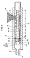
- FIG. 1 is an enlarged sectional view of a main portion of an injection apparatus according to an embodiment of the present invention
- FIG. 2 is a schematic view of the injection apparatus according to the embodiment of the present invention.
- reference numeral 11 denotes a heating cylinder serving as a cylinder member
- reference numeral 12 denotes a screw which is disposed within the heating cylinder 11 such that the screw 12 can be rotated and can be reciprocated and which serves as an injection member
- reference numeral 13 denotes an injection nozzle formed at the front end (the left end in FIG. 1) of the heating cylinder 11
- reference numeral 14 denotes a nozzle opening formed in the injection nozzle 13
- reference numeral 15 denotes a resin supply port formed in the heating cylinder 11 at a predetermined position in the vicinity of the rear end (the right end in FIG. 1) of the heating cylinder 11
- reference numeral 16 denotes a hopper attached to the resin supply port 15 and adapted to accommodate pellets of resin.
- the screw 12 has a flight portion 21 and a screw head 27 disposed at the front end of the flight portion 21.
- the flight portion 21 includes a spiral flight 23 formed on the outer circumferential surface of the screw body, so that a spiral groove 24 is formed by the flight 23.
- a resin supply section P1 to which pellets of resin are supplied from the hopper 16, a compression section P2 in which the supplied resin is melted while being compressed, and a metering section P3 in which a predetermined amount of the molten resin is measured are formed, in this order from the rear side (the right side in FIG. 1) toward the front side (the left side in FIG. 1).
- the diameter of the screw 12 measured at the bottom of the groove 24 is set to a relatively small value in the resin supply section P1, and is increased gradually from the rear side toward the front side in the compression section P2, so that the diameter becomes relatively large in the metering section P3. Therefore, the clearance between the inner circumferential surface of the heating cylinder 11 and the bottom of the groove 24 of the screw 12 is relatively large in the resin supply section P1, and decreases gradually from the rear side toward the front side in the compression section P2, so that the clearance becomes relatively small in the metering section P3.
- the resin accumulated in front of the screw head 27 is injected from the injection nozzle 13 and charged into a cavity of an unillustrated mold unit.
- a backflow prevention unit is disposed around the screw head 27.
- the screw head 27 has a conical head body 25 at its front side and a shaft portion 26 at its rear side.
- An annular backflow prevention ring 28 is rotatably disposed to surround the shaft portion 26, and a press metal plate 29 is fixed to the front end of the flight portion 21.
- the backflow prevention ring 28 and the press metal plate 29 constitute the backflow prevention unit.
- An axially-extending hole 28a is formed in the backflow prevention ring 28 at a plurality of positions in the circumferential direction; and a cutaway 28b is formed at the front end of the backflow prevention ring 28 to extend over a predetermined angle.
- An engagement projection 25a formed on the head body 25 is received in the cutaway 28b.
- an axially-extending hole 29a is formed in the press metal plate 29 at a plurality of circumferential positions corresponding to those of the holes 28a. Accordingly, when the backflow prevention ring 28 rotates relative to the screw head 27, communication between the holes 28a and 29a is established selectively.
- the backflow prevention ring 28 assumes a communication position in which the space on the front side of the screw head 27 communicates with the flight portion 21, and a shut-off position in which the communication between the space on the front side of the screw head 27 and the flight portion 21 is broken.
- the rear end (right end in FIG. 2) of the heating cylinder 11 is fixed to a front injection support 31, and a rear injection support 32 is disposed to be separated a predetermined distance from the front injection support 31.
- Guide bars 33 are disposed and extend between the front injection support 31 and the rear injection support 32, and a pressure plate 34 is disposed such that the pressure plate 34 can advance and retract along the guide bars 33.
- the front injection support 31 and the rear injection support 32 are fixed to an unillustrated slide base by use of unillustrated bolts.
- a drive shaft 35 is connected to the rear end of the screw 12, and the drive shaft 35 is rotatably supported by the pressure plate 34 via bearings 36 and 37.
- a metering motor (electric motor) 41 is disposed as first drive means; and first rotation transmission means composed of pulleys 42 and 43 and a timing belt 44 is disposed between the metering motor 41 and the drive shaft 35. Therefore, the screw 12 can be rotated forward and backward through drive of the metering motor 41.
- the electric metering motor 41 is used as the first drive means.
- a hydraulic motor may be used.
- a ball screw 47 which is composed of a ball screw shaft 45 and a ball nut 46 in mutual screw-engagement, is disposed on the rear side (on the right side in FIG. 2) of the pressure plate 34.
- the ball screw 47 serves as motion conversion means for converting rotational motion to linear motion.
- the ball screw shaft 45 is rotatably supported by the rear injection support 32 via a bearing 48, and the ball nut 46 is fixed to the pressure plate 34 via a plate 51 and a load cell 52.
- an injection motor 53 is disposed as second drive means; and second rotation transmission means composed of pulleys 54 and 55 and a timing belt 56 is disposed between the injection motor 53 and the ball screw shaft 45.
- the ball screw shaft 45 is rotated through drive of the injection motor 53, the ball nut 46 and the pressure plate 34 are moved, whereby the screw 12 is advanced (moved leftward in FIG. 2) and retracted (moved rightward in FIG. 2).
- the injection motor 53 is used as means for moving the pressure plate 34.
- an injection cylinder may be used.
- FIG. 3 is a block diagram of a main portion of a control circuit for the injection apparatus according to the embodiment of the present invention
- FIG. 4 is a schematic block diagram of the control circuit for the injection apparatus according to the embodiment of the present invention
- FIG. 5 is a time chart showing operation of the injection apparatus according to the embodiment of the present invention.
- a positive value indicates that the metering motor 41 or the injection motor 53 is driven in the forward direction
- a negative value indicates that the metering motor 41 or the injection motor 53 is driven in the reverse direction.
- reference numeral 41 denotes a metering motor
- 52 denotes a load cell
- 53 denotes an injection motor
- 62 denotes a controller
- 64 denotes an injection servo-amplifier
- 65 denotes a metering servo-amplifier
- 66 denotes a screw-speed setting unit serving as screw-speed setting means
- 67 denotes a memory serving as memory means
- 68 denotes a flight-speed setting unit
- 71 denotes an injection-motor-rotational-speed detector for detecting rotational speed n I of the injection motor 53
- 72 denotes a metering-motor-rotational-speed detector for detecting rotational speed n M of the metering motor 41
- 81 denotes a screw position detector for detecting the position of the screw 12 (FIG. 2).
- the controller 62 includes an injection-motor-rotational-speed setting unit 73, subtracters 74 and 78, a gain setting unit (-K) 75 serving as metering-motor-rotational-speed calculation means, and a metering-motor-rotational-speed setting unit 77.
- the metering-motor-rotational-speed setting unit 77 supplies a preset metering-motor-rotational-speed command N M to the subtracter 78.
- the subtracter 78 receives the metering-motor-rotational-speed command N M and the metering-motor-rotational-speed n M , calculates the deviation ⁇ n M between the metering-motor-rotational-speed command N M and the metering-motor-rotational-speed n M , and sends the deviation ⁇ n M to the metering servo-amplifier 65 in the form of a current command I M .
- the controller 62 drives the metering motor 41.
- the subtracter 74 receives the injection-motor-rotational-speed command N Ii and the injection-motor-rotational-speed n I , calculates the deviation ⁇ n I between the injection-motor-rotational-speed command N Ii and the injection-motor-rotational-speed n I , and sends the deviation ⁇ n I to the injection servo-amplifier 64 in the form of a current command I I . In this manner, the controller 62 drives the injection motor 53.
- the resin within the groove 24 (FIG. 1) rotates together with the screw 12 and does not advance.
- the inner circumferential surface of the heating cylinder 11 is made rougher than the outer circumferential surface of the screw 12.
- the inner circumferential surface of the heating cylinder 11 is made rougher than the outer circumferential surface of the screw 12, when the screw 12 is advanced, a large frictional resistance acts on the resin in the vicinity of the inner circumferential surface of the heating cylinder 11.
- the state of the resin within the groove 24 changes while the resin moves from the resin supply section P1 to the compression section P2 and further to the metering section P3, the frictional resistance acting on the resin varies accordingly.
- the screw 12 when the screw 12 is advanced through drive of the injection motor 53 during the injection step, the screw 12 is rotated in the reverse direction through drive of the metering motor 41, whereby the apparent advancement speed of the flight 23 relative to the heating cylinder 11; i.e., the flight speed Vf, is made lower than the screw speed Vs.
- the flight-speed setting unit 68 sends to the gain setting unit 75 the speed ratio ⁇ which has been preset in the above-described manner.
- the subtracter 78 receives the metering-motor-rotational-speed command N Fi and the metering-motor-rotational-speed n M , calculates the deviation ⁇ n F between the metering-motor-rotational-speed command N Fi and the metering-motor-rotational-speed n M , and sends the deviation ⁇ n F to the metering servo-amplifier 65 in the form of a current command I F .
- the controller 62 drives the metering motor 41.
- a screw-rotational-speed setting unit may be disposed.
- a screw rotational speed set by use of the screw-rotational-speed setting unit is supplied to the controller 62.
- the gain setting unit 75 and the subtracter 78 constitute flight speed control means, which performs flight speed control in order to control the flight speed Vf.
- the screw 12 is rotated at the screw rotational speed Nf.
- the above-described control may be modified such that the metering-motor-rotational-speed command N Fi is previously stored in the memory 67 and is read out therefrom in order to perform flight speed control.
- the control may be modified such that the metering-motor-rotational-speed command N Fi is previously stored in the memory 67 in the form of a rotational speed pattern, and the rotational speed pattern is read out therefrom in order to perform flight speed control.
- the frictional resistance acting on the resin can be maintained constant, so that the injection pressure can be stabilized. Therefore, the mold inner pressure can be stabilized, whereby quality of molded products can be improved.
- the backflow prevention ring 28 is always biased toward the shut-off position. Accordingly, the possibility of the backflow prevention ring 28 being moved to the communication position during the injection step due to reception of an external force is eliminated, so that reverse flow of resin can be prevented. As a result, metering can be performed stably, whereby quality of molded products can be improved.
- Unillustrated communication control means of the controller 62 drives the metering motor 41 in the forward direction at time t1 to thereby rotate the screw 12 in the forward direction at a screw rotational speed N1 for a period ⁇ 1. Accordingly, the backflow prevention ring 28 is rotated by an angle ⁇ relative to the screw 12, so that the backflow prevention ring 28 is positioned at the communication position in order to establish communication between the holes 28a and 29a. Subsequently, a metering step is started at time t2 in order to perform metering operation. Specifically, unillustrated metering control means of the controller 62 drives the metering motor 41 in the forward direction to thereby rotate the screw 12 in the forward direction at a screw rotational speed N2 for a period ⁇ 2.
- the backflow prevention ring 28 is placed at the communication position, so that the holes 28a and 29a communicate with each other.
- the resin flows forward through the holes 28a and 29a and is accumulated in front of the screw head 27. With the accumulation of the resin, the screw 12 is retracted.
- shut-off control means of the controller 62 drives the metering motor 41 in the reverse direction at time t4 to thereby rotate the screw 12 in the reverse direction at a screw rotational speed N3 for a period ⁇ 3. Accordingly, the backflow prevention ring 28 is rotated by an angle ⁇ relative to the screw 12, so that the backflow prevention ring 28 is positioned at the shut-off position in order to break the communication between the holes 28a and 29a.
- unillustrated first screw-advancement control means of the controller 62 drives the injection motor 53 at time t5 to thereby advance the screw 12 by a predetermined amount or distance.
- the injection pressure detected by the load cell 52 reaches a preset pressure at time t6
- the screw 12 is stopped.
- the injection-motor-rotational-speed setting unit 73 generates an injection-motor-rotational-speed command N IA , and sends the injection-motor-rotational-speed command N IA to the subtracter 74 and the gain setting unit 75.
- the subtracter 74 receives the injection-motor-rotational-speed command N IA and the injection-motor-rotational-speed n I , calculates the deviation ⁇ n IA between the injection-motor-rotational-speed command N IA and the injection-motor-rotational-speed n I , and sends the deviation ⁇ n IA to the injection servo-amplifier 64 in the form of a current command I IA .
- the controller 62 drives the injection motor 53 in the forward direction.
- Unillustrated reference position setting means of the controller 62 regards as a reference position the screw position at which the screw 12 has been stopped at time t6 and stores the screw position in the memory 67.
- the backflow prevention ring 28 is placed at the shut-off position; the screw 12 is advanced over a predetermined distance through drive of the injection motor 53 and is stopped when the injection pressure reaches the preset pressure; and the screw position at that time is regarded and stored as a reference position. Therefore, the injection pressure at the time of starting the injection step does not involve variation. Accordingly, neither sink marks nor burrs are formed on molded products, so that the molded products have improved quality.
- the inner circumferential surface of the heating cylinder 11 is made rougher than the outer circumferential surface of the screw 12, when the screw 12 is advanced to the reference position after completion of the metering step, the relationship between the injection pressure and the position of the screw 12 changes if a large frictional resistance acts on resin in the vicinity of the inner circumferential surface of the heating cylinder 11. Therefore, even when the screw 12 is stopped when the injection pressure reaches the preset pressure, the stopped position of the screw 12 varies. As a result, the reference position varies, which lowers the quality of molded products.
- the gain setting unit 75 and the subtracter 78 drive the metering motor 41 in the reverse direction to thereby make the flight speed Vf lower than the screw speed Vs.
- the gain setting unit 75 calculates a metering-motor-rotational-speed command N FA serving as a flight speed command, while using the speed ratio ⁇ as a gain, and sends the metering-motor-rotational-speed command N FA to the subtracter 78.
- the subtracter 78 Upon reception of the metering-motor-rotational-speed command N FA and the metering-motor-rotational-speed n M , the subtracter 78 calculates the deviation ⁇ n FA between the metering-motor-rotational-speed command N FA and the metering-motor-rotational-speed n M , and sends the deviation ⁇ n FA to the metering servo-amplifier 65 in the form of a current command I FA . In this manner, the screw 12 is rotated in the reverse direction at the screw rotational speed Nf.
- the above-described speed ratio ⁇ is set to satisfy the following relation as in the case of the injection step. 0 ⁇ ⁇ ⁇ 1
- the flight speed Vf is rendered lower than the screw speed Vs, so that the resin slides along the outer circumferential surface of the screw 12 and stagnates on the inner circumferential surface of the heating cylinder 11. Accordingly, the frictional resistance acting on the resin in the vicinity of the inner circumferential surface of the heating cylinder 11 can be reduced.
- the relationship between the injection pressure and the position of the screw 12 is prevented from changing. Therefore, when the screw 12 is stopped when the injection pressure reaches the preset pressure, the stopped position of the screw 12 becomes constant (i.e., is without variation). As a result, the reference position is prevented from varying, whereby the quality of molded products can be improved.
- unillustrated suck-back means of the controller 62 drives the injection motor 53 in the reverse direction at time t7 in order to retract the screw 12 from the reference position by a predetermined distance, thereby effecting suck-back operation.
- an injection step is started at time t8.
- unillustrated injection control means and second screw-advancement control means of the controller 62 drive the injection motor 53 in the forward direction in accordance with the injection-motor-rotational-speed command N Ii to thereby advance the screw 12 at a predetermined screw speed Vs by a preset distance from the reference position.
- the resin accumulated in front of the screw head 27 is injected from the injection nozzle 13.
- a portion of the resin accumulated in front of the screw head 27 is apt to flow backward or move rearward.
- the communication between the holes 28a and 29a is broken, reverse flow of the resin in front of the screw head 27 can be prevented.
- the quantity of resin charged into a mold during the injection step can be stabilized, so that quality of molded products can be improved. Further, since the resin pressure within the flight portion 21 during the injection step can be stabilized, metering can be performed stably in the metering step, whereby the thermal history of the resin can be stabilized and the temperature of the resin can be stabilized.
- the preset distance is calculated on the basis of a quantity of resin to be charged into the cavity of the mold, and a distance over which the screw 12 retracts during the suck-back operation.
- the gain setting unit 75 and the subtracter 78 drive the metering motor 41 in the reverse direction in accordance with the metering-motor-rotational-speed command N Fi to thereby advance the flight 23 at the above-described flight speed Vf, which is apparently lower than the screw speed Vs.
- a minimum value ⁇ MIN of the speed ratio ⁇ is set for each type of resin.
- the speed ratio ⁇ is set to be less than 1 but not less than the minimum value ⁇ MIN ; e.g., in the range of 0.1 to 0.9.
- the flight speed Vf i can be changed in accordance with the screw speed Vs i .
- the controller 62 changes its control mode from speed control to pressure control, and performs pressure holding control on the basis of the above-described injection force. Subsequently, the controller 62 completes the injection step at time t9.
- a slight delay is provided between completion of forward rotation of the screw 12 for the period ⁇ 1 and start of the metering step.
- the metering step may be started immediately after completion of forward rotation of the screw 12 for the period ⁇ 1.
- a slight delay is provided between completion of the metering step and start of reverse rotation of the screw 12.
- the reverse rotation of the screw 12 may be started immediately after completion of the metering step.
- a slight delay is provided between completion of the reverse rotation of the screw 12 and start of advancement of the screw 12 at time t5.
- the advancement of the screw 12 may be started immediately after completion of the reverse rotation of the screw 12.
- a slight delay is provided between completion of the advancement of the screw 12 started at time t5 and start of suck-back operation.
- the suck-back operation may be started immediately after completion of the advancement of the screw 12.
- a slight delay is provided between completion of the suck-back operation and start of the injection step.
- the injection step may be started immediately after completion of the suck-back operation.
- the speed ratio ⁇ is set to 0. 1 to 0. 3, preferably to about 0. 2
- the speed ratio ⁇ is set to 0. 4 to 0. 6, preferably to about 0. 5. This setting minimizes the frictional resistance, without rendering the resin pressure within the flight portion 21 negative.
- the above-described operation may be modified as follows.
- the period ⁇ 3 (FIG. 5) is increased;
- the above-described shut-off control means is operated in the first half of the period ⁇ 3 in order to move the backflow prevention ring 28 to the shut-off position; and unillustrated resin-pressure decreasing means of the controller 62 is operated in the second half of the period ⁇ 3 in order to reduce by a predetermined amount the resin pressure in the vicinity of the forward end of the flight portion 21.
- the frictional resistance acting on the resin can be reduced before start of the injection step, the injection pressure during the injection step can be stabilized more effectively.
- the screw 12 is rotated in the reverse direction at a screw rotational speed Nf until a predetermined period of time has elapsed after start of advancement of the screw 12 in order to advance the flight 23 at a flight speed Vf which is apparently lower than the screw speed Vs; and after elapse of the predetermined period of time, the metering motor 41 is stopped in order to advance the flight 23 at a flight speed Vf that is apparently equal to the screw speed Vs.
Landscapes
- Engineering & Computer Science (AREA)
- Manufacturing & Machinery (AREA)
- Mechanical Engineering (AREA)
- Injection Moulding Of Plastics Or The Like (AREA)
- Steering Control In Accordance With Driving Conditions (AREA)
- Percussion Or Vibration Massage (AREA)
- Control Of Non-Electrical Variables (AREA)
Abstract
Description
Claims (12)
- An injection apparatus comprising:(a) a heating cylinder;(b) a screw disposed within the heating cylinder to be rotatable and reciprocatable, the screw having a flight portion in which a flight is formed on an outer circumference of a screw body, and a screw head disposed at a front end of the flight portion;(c) first drive means for rotating the screw;(d) second drive means for advancing and retracting the screw;(e) screw-advancement control means for driving the second drive means in an injection step in order to advance the screw at a predetermined screw speed; and(f) flight speed control means for driving the first drive means in the injection step in order to advance the flight at a flight speed that is apparently lower than the screw speed.
- An injection apparatus according to claim 1, wherein(a) a backflow prevention ring is disposed to surround the screw head; and(b) upon rotation of the screw, the backflow prevention ring rotates by a predetermined amount relative to the screw head to assume a communication position in which a space on a front side of the screw head communicates with the flight portion, and a shut-off position in which the communication between the space on the front side of the screw head and the flight portion is broken.
- An injection apparatus according to claim 1, wherein the speed ratio of the flight speed to the screw speed is set to be less than 1 and not less than a minimum value set for a type of resin.
- An injection apparatus according to claim 1, wherein(a) the screw speed is changed in a plurality of steps; and(b) the flight speed is changed in a plurality of steps in accordance with the screw speed.
- An injection apparatus according to claim 1, further comprising:(a) shut-off control means for rotating the screw in a reverse direction in order to move the backflow prevention ring to the shut-off position, in a first stage before start of the injection step; and(b) resin-pressure reduction means for rotating the screw in the reverse direction in order to reduce resin pressure within the flight portion, in a second stage before start of the injection step.
- An injection apparatus according to claim 1, wherein the flight speed control means advances the flight at a flight speed that is apparently lower than the screw speed until a predetermined period of time has elapsed after start of the injection step, and advances the flight at a flight speed that is apparently equal to the screw speed after elapse of the predetermined period of time.
- An injection apparatus comprising:(a) a heating cylinder;(b) a screw disposed within the heating cylinder to be rotatable and reciprocatable, the screw having a flight portion in which a flight is formed on an outer circumference of a screw body, and a screw head disposed at a front end of the flight portion;(c) first drive means for rotating the screw;(d) second drive means for advancing and retracting the screw;(e) first screw-advancement control means for driving the second drive means during a period between completion of a metering step and start of an injection step in order to advance the screw at a predetermined screw speed by a predetermined amount such that the screw is positioned at a reference position;(f) flight speed control means for driving the first drive means, during the advancement of the screw by the predetermined amount, in order to advance the flight at a flight speed that is apparently lower than the screw speed; and(g) second screw-advancement control means for driving the second drive means in the injection step in order to advance the screw at a predetermined screw speed.
- An injection apparatus according to claim 7, wherein the flight speed control means drives the first drive means during the injection step in order to advance the flight at a flight speed that is apparently lower than the screw speed.
- An injection apparatus according to claim 7, wherein the flight speed is zero.
- A method of controlling an injection apparatus, comprising the steps of:(a) driving first drive means in a metering step in order to rotate a screw in a forward direction; and(b) driving second drive means in an injection step in order to advance the screw at a predetermined screw speed and driving the first drive means in the injection step in order to advance a flight at a flight speed that is apparently lower than the screw speed.
- A method of controlling an injection apparatus, comprising the steps of:(a) driving first drive means in a metering step in order to rotate a screw in a forward direction;(b) driving second drive means, during a period between completion of the metering step and start of an injection step, in order to advance the screw at a predetermined screw speed by a predetermined amount to thereby place the screw at a reference position;(c) driving the first drive means, during the advancement of the screw by the predetermined amount, in order to advance a flight at a flight speed that is apparently lower than the screw speed; and(d) driving the second drive means during the injection step in order to advance the screw at a predetermined screw speed.
- A method of controlling an injection apparatus according to claim 11, wherein the flight speed is zero.
Applications Claiming Priority (2)
| Application Number | Priority Date | Filing Date | Title |
|---|---|---|---|
| JP20924699 | 1999-07-23 | ||
| JP20924699A JP3336296B2 (en) | 1999-07-23 | 1999-07-23 | Injection device and control method thereof |
Publications (3)
| Publication Number | Publication Date |
|---|---|
| EP1077123A2 true EP1077123A2 (en) | 2001-02-21 |
| EP1077123A3 EP1077123A3 (en) | 2003-01-08 |
| EP1077123B1 EP1077123B1 (en) | 2008-10-22 |
Family
ID=16569789
Family Applications (1)
| Application Number | Title | Priority Date | Filing Date |
|---|---|---|---|
| EP00115767A Expired - Lifetime EP1077123B1 (en) | 1999-07-23 | 2000-07-21 | Injection apparatus and method of controlling the same |
Country Status (9)
| Country | Link |
|---|---|
| US (1) | US6321940B1 (en) |
| EP (1) | EP1077123B1 (en) |
| JP (1) | JP3336296B2 (en) |
| KR (1) | KR100341007B1 (en) |
| CN (1) | CN1124924C (en) |
| AT (1) | ATE411889T1 (en) |
| DE (1) | DE60040582D1 (en) |
| SG (1) | SG91878A1 (en) |
| TW (1) | TW487627B (en) |
Cited By (2)
| Publication number | Priority date | Publication date | Assignee | Title |
|---|---|---|---|---|
| EP1072387A3 (en) * | 1999-07-30 | 2002-03-27 | Sumitomo Heavy Industries, Ltd. | Method and apparatus for adjusting zero point of a pressure sensor of an injection apparatus |
| EP1207032A1 (en) * | 2000-11-15 | 2002-05-22 | Sumitomo Heavy Industries, Ltd. | Method for controlling injection molding machine capable of reducing variations in weight of molded product |
Families Citing this family (7)
| Publication number | Priority date | Publication date | Assignee | Title |
|---|---|---|---|---|
| EP1657804A1 (en) * | 2004-11-09 | 2006-05-17 | 3M Espe Ag | Method of mixing and extruding viscous materials and gearbox for dispensing the same |
| JP4672042B2 (en) * | 2008-04-18 | 2011-04-20 | 日精樹脂工業株式会社 | Screw driving method and apparatus for injection molding machine |
| JP4945662B2 (en) * | 2010-06-21 | 2012-06-06 | ファナック株式会社 | Injection molding machine having resin supply amount adjusting means |
| JP5647044B2 (en) * | 2011-03-17 | 2014-12-24 | 住友重機械工業株式会社 | Injection molding machine and method for adjusting injection molding machine |
| US20170015036A1 (en) * | 2014-05-30 | 2017-01-19 | Mitsubishi Heavy Industries Plastic Technology Co., Ltd. | Injection molding method, screw, and injection molding machine |
| CN110315712B (en) * | 2019-07-09 | 2021-05-18 | 深圳市鸿成飞模塑有限公司 | Uniform injection device based on injection mold |
| JP7326117B2 (en) * | 2019-10-31 | 2023-08-15 | 住友重機械工業株式会社 | Injection molding machine |
Family Cites Families (11)
| Publication number | Priority date | Publication date | Assignee | Title |
|---|---|---|---|---|
| US3889849A (en) * | 1973-12-26 | 1975-06-17 | Gen Electric | Shot volume and cushion point control for injection molding apparatus |
| US3888393A (en) * | 1974-01-22 | 1975-06-10 | Mordeki Drori | Injection molder with ram movable indepently of screw feeder |
| GB1572514A (en) * | 1976-04-23 | 1980-07-30 | Durapipe Ltd | Moulding of synthetic plastics products |
| US4667852A (en) * | 1983-09-29 | 1987-05-26 | Bernd Siemann | Apparatus for preparing and dispensing thermoplastic resin |
| JPS6076321A (en) * | 1983-10-04 | 1985-04-30 | Toshiba Mach Co Ltd | Injection molding process |
| JPS61235119A (en) * | 1985-04-12 | 1986-10-20 | Nissei Plastics Ind Co | Method and device for controlling injection of injection molding machine |
| JPS63265615A (en) * | 1987-01-23 | 1988-11-02 | Komatsu Ltd | Molding control method of injection molding machine |
| JPH07100336B2 (en) * | 1987-05-21 | 1995-11-01 | 東芝機械株式会社 | Thick product molding method |
| DE3835250C1 (en) * | 1988-10-15 | 1990-05-10 | Heinrich Koch Plastmaschinen Gmbh & Co Kg, 5200 Siegburg, De | |
| JP3142712B2 (en) * | 1994-04-07 | 2001-03-07 | 東芝機械株式会社 | Injection molding machine |
| JP3749783B2 (en) * | 1997-12-26 | 2006-03-01 | 東洋機械金属株式会社 | Injection molding machine |
-
1999
- 1999-07-23 JP JP20924699A patent/JP3336296B2/en not_active Expired - Fee Related
-
2000
- 2000-07-18 TW TW089114316A patent/TW487627B/en not_active IP Right Cessation
- 2000-07-18 US US09/618,717 patent/US6321940B1/en not_active Expired - Lifetime
- 2000-07-21 DE DE60040582T patent/DE60040582D1/en not_active Expired - Lifetime
- 2000-07-21 SG SG200004108A patent/SG91878A1/en unknown
- 2000-07-21 EP EP00115767A patent/EP1077123B1/en not_active Expired - Lifetime
- 2000-07-21 AT AT00115767T patent/ATE411889T1/en active
- 2000-07-21 CN CN00121357A patent/CN1124924C/en not_active Expired - Fee Related
- 2000-07-22 KR KR1020000042267A patent/KR100341007B1/en not_active Expired - Fee Related
Cited By (3)
| Publication number | Priority date | Publication date | Assignee | Title |
|---|---|---|---|---|
| EP1072387A3 (en) * | 1999-07-30 | 2002-03-27 | Sumitomo Heavy Industries, Ltd. | Method and apparatus for adjusting zero point of a pressure sensor of an injection apparatus |
| US6514442B1 (en) | 1999-07-30 | 2003-02-04 | Sumitomo Heavy Industries, Ltd. | Method and apparatus for adjusting zero point of a pressure sensor of an injection apparatus |
| EP1207032A1 (en) * | 2000-11-15 | 2002-05-22 | Sumitomo Heavy Industries, Ltd. | Method for controlling injection molding machine capable of reducing variations in weight of molded product |
Also Published As
| Publication number | Publication date |
|---|---|
| DE60040582D1 (en) | 2008-12-04 |
| JP2001030317A (en) | 2001-02-06 |
| EP1077123B1 (en) | 2008-10-22 |
| SG91878A1 (en) | 2002-10-15 |
| TW487627B (en) | 2002-05-21 |
| CN1124924C (en) | 2003-10-22 |
| JP3336296B2 (en) | 2002-10-21 |
| ATE411889T1 (en) | 2008-11-15 |
| CN1281782A (en) | 2001-01-31 |
| KR100341007B1 (en) | 2002-06-20 |
| EP1077123A3 (en) | 2003-01-08 |
| US6321940B1 (en) | 2001-11-27 |
| KR20010049857A (en) | 2001-06-15 |
Similar Documents
| Publication | Publication Date | Title |
|---|---|---|
| US6321940B1 (en) | Injection apparatus and method of controlling the same | |
| US6854967B2 (en) | Electric injection molding machine for controlling injection speed and injection pressure of electric injection molding machine | |
| EP1072387B1 (en) | Method and apparatus for adjusting zero point of a pressure sensor of an injection apparatus | |
| JP3299235B2 (en) | Operation method of backflow prevention device and injection device | |
| EP0965430B1 (en) | Method for controlling drive of screw in injection molding machine | |
| JP3439152B2 (en) | Injection device and control method thereof | |
| JP3337205B2 (en) | Injection device and control method thereof | |
| JP3336301B2 (en) | Injection device and control method thereof | |
| JP3321437B2 (en) | Injection device and control method thereof | |
| JP3314054B2 (en) | Injection device and control method thereof | |
| JP3534990B2 (en) | Control method of injection molding machine | |
| JP3329774B2 (en) | Injection device and control method thereof | |
| JP3142712B2 (en) | Injection molding machine | |
| US20030230829A1 (en) | Injection apparatus and molding method in injection molding machine | |
| JP3607588B2 (en) | Injection device and control method thereof | |
| JP3535063B2 (en) | Injection molding machine | |
| JP3312017B2 (en) | Injection equipment | |
| JP4208043B2 (en) | Position detection apparatus and position detection method for injection molding machine | |
| JP3321438B2 (en) | Injection equipment | |
| JP3607602B2 (en) | Injection device and control method thereof | |
| KR100467824B1 (en) | Extrude cast machine | |
| JPH11147239A (en) | Injection control method | |
| JPH1110696A (en) | Metering method in injection molding machine | |
| JPH11115017A (en) | Control method of injection molding machine | |
| JP2001353762A (en) | Injecting unit |
Legal Events
| Date | Code | Title | Description |
|---|---|---|---|
| PUAI | Public reference made under article 153(3) epc to a published international application that has entered the european phase |
Free format text: ORIGINAL CODE: 0009012 |
|
| AK | Designated contracting states |
Kind code of ref document: A2 Designated state(s): AT BE CH CY DE DK ES FI FR GB GR IE IT LI LU MC NL PT SE |
|
| AX | Request for extension of the european patent |
Free format text: AL;LT;LV;MK;RO;SI |
|
| PUAL | Search report despatched |
Free format text: ORIGINAL CODE: 0009013 |
|
| AK | Designated contracting states |
Kind code of ref document: A3 Designated state(s): AT BE CH CY DE DK ES FI FR GB GR IE IT LI LU MC NL PT SE |
|
| AX | Request for extension of the european patent |
Free format text: AL;LT;LV;MK;RO;SI |
|
| RIC1 | Information provided on ipc code assigned before grant |
Free format text: 7B 29C 45/50 A, 7B 29C 45/76 B |
|
| 17P | Request for examination filed |
Effective date: 20030707 |
|
| AKX | Designation fees paid |
Designated state(s): AT CH DE FR GB IT LI |
|
| 17Q | First examination report despatched |
Effective date: 20050202 |
|
| 17Q | First examination report despatched |
Effective date: 20050202 |
|
| GRAP | Despatch of communication of intention to grant a patent |
Free format text: ORIGINAL CODE: EPIDOSNIGR1 |
|
| GRAS | Grant fee paid |
Free format text: ORIGINAL CODE: EPIDOSNIGR3 |
|
| GRAA | (expected) grant |
Free format text: ORIGINAL CODE: 0009210 |
|
| AK | Designated contracting states |
Kind code of ref document: B1 Designated state(s): AT CH DE FR GB IT LI |
|
| REG | Reference to a national code |
Ref country code: GB Ref legal event code: FG4D |
|
| REG | Reference to a national code |
Ref country code: CH Ref legal event code: EP |
|
| REG | Reference to a national code |
Ref country code: CH Ref legal event code: NV Representative=s name: RIEDERER HASLER & PARTNER PATENTANWAELTE AG |
|
| REF | Corresponds to: |
Ref document number: 60040582 Country of ref document: DE Date of ref document: 20081204 Kind code of ref document: P |
|
| PLBE | No opposition filed within time limit |
Free format text: ORIGINAL CODE: 0009261 |
|
| STAA | Information on the status of an ep patent application or granted ep patent |
Free format text: STATUS: NO OPPOSITION FILED WITHIN TIME LIMIT |
|
| 26N | No opposition filed |
Effective date: 20090723 |
|
| GBPC | Gb: european patent ceased through non-payment of renewal fee |
Effective date: 20090721 |
|
| REG | Reference to a national code |
Ref country code: FR Ref legal event code: ST Effective date: 20100331 |
|
| PG25 | Lapsed in a contracting state [announced via postgrant information from national office to epo] |
Ref country code: FR Free format text: LAPSE BECAUSE OF NON-PAYMENT OF DUE FEES Effective date: 20090731 |
|
| PG25 | Lapsed in a contracting state [announced via postgrant information from national office to epo] |
Ref country code: GB Free format text: LAPSE BECAUSE OF NON-PAYMENT OF DUE FEES Effective date: 20090721 |
|
| PGFP | Annual fee paid to national office [announced via postgrant information from national office to epo] |
Ref country code: CH Payment date: 20130712 Year of fee payment: 14 |
|
| PGFP | Annual fee paid to national office [announced via postgrant information from national office to epo] |
Ref country code: IT Payment date: 20130716 Year of fee payment: 14 |
|
| PGFP | Annual fee paid to national office [announced via postgrant information from national office to epo] |
Ref country code: DE Payment date: 20140716 Year of fee payment: 15 |
|
| PGFP | Annual fee paid to national office [announced via postgrant information from national office to epo] |
Ref country code: AT Payment date: 20140626 Year of fee payment: 15 |
|
| REG | Reference to a national code |
Ref country code: CH Ref legal event code: PL |
|
| PG25 | Lapsed in a contracting state [announced via postgrant information from national office to epo] |
Ref country code: CH Free format text: LAPSE BECAUSE OF NON-PAYMENT OF DUE FEES Effective date: 20140731 Ref country code: IT Free format text: LAPSE BECAUSE OF NON-PAYMENT OF DUE FEES Effective date: 20140721 Ref country code: LI Free format text: LAPSE BECAUSE OF NON-PAYMENT OF DUE FEES Effective date: 20140731 |
|
| REG | Reference to a national code |
Ref country code: DE Ref legal event code: R119 Ref document number: 60040582 Country of ref document: DE |
|
| REG | Reference to a national code |
Ref country code: AT Ref legal event code: MM01 Ref document number: 411889 Country of ref document: AT Kind code of ref document: T Effective date: 20150721 |
|
| PG25 | Lapsed in a contracting state [announced via postgrant information from national office to epo] |
Ref country code: DE Free format text: LAPSE BECAUSE OF NON-PAYMENT OF DUE FEES Effective date: 20160202 |
|
| PG25 | Lapsed in a contracting state [announced via postgrant information from national office to epo] |
Ref country code: AT Free format text: LAPSE BECAUSE OF NON-PAYMENT OF DUE FEES Effective date: 20150721 |