EP1076471A2 - Optical wavelength division multiplexing transmission network device - Google Patents
Optical wavelength division multiplexing transmission network device Download PDFInfo
- Publication number
- EP1076471A2 EP1076471A2 EP00402253A EP00402253A EP1076471A2 EP 1076471 A2 EP1076471 A2 EP 1076471A2 EP 00402253 A EP00402253 A EP 00402253A EP 00402253 A EP00402253 A EP 00402253A EP 1076471 A2 EP1076471 A2 EP 1076471A2
- Authority
- EP
- European Patent Office
- Prior art keywords
- port
- wavelength
- port group
- transmitting
- awg
- Prior art date
- Legal status (The legal status is an assumption and is not a legal conclusion. Google has not performed a legal analysis and makes no representation as to the accuracy of the status listed.)
- Granted
Links
Images









Classifications
-
- H—ELECTRICITY
- H04—ELECTRIC COMMUNICATION TECHNIQUE
- H04B—TRANSMISSION
- H04B10/00—Transmission systems employing electromagnetic waves other than radio-waves, e.g. infrared, visible or ultraviolet light, or employing corpuscular radiation, e.g. quantum communication
- H04B10/25—Arrangements specific to fibre transmission
- H04B10/2581—Multimode transmission
-
- H—ELECTRICITY
- H04—ELECTRIC COMMUNICATION TECHNIQUE
- H04J—MULTIPLEX COMMUNICATION
- H04J14/00—Optical multiplex systems
- H04J14/02—Wavelength-division multiplex systems
- H04J14/0278—WDM optical network architectures
- H04J14/0282—WDM tree architectures
-
- H—ELECTRICITY
- H04—ELECTRIC COMMUNICATION TECHNIQUE
- H04B—TRANSMISSION
- H04B10/00—Transmission systems employing electromagnetic waves other than radio-waves, e.g. infrared, visible or ultraviolet light, or employing corpuscular radiation, e.g. quantum communication
- H04B10/25—Arrangements specific to fibre transmission
-
- H—ELECTRICITY
- H04—ELECTRIC COMMUNICATION TECHNIQUE
- H04J—MULTIPLEX COMMUNICATION
- H04J14/00—Optical multiplex systems
- H04J14/02—Wavelength-division multiplex systems
- H04J14/0227—Operation, administration, maintenance or provisioning [OAMP] of WDM networks, e.g. media access, routing or wavelength allocation
-
- H—ELECTRICITY
- H04—ELECTRIC COMMUNICATION TECHNIQUE
- H04J—MULTIPLEX COMMUNICATION
- H04J14/00—Optical multiplex systems
- H04J14/02—Wavelength-division multiplex systems
- H04J14/0227—Operation, administration, maintenance or provisioning [OAMP] of WDM networks, e.g. media access, routing or wavelength allocation
- H04J14/0241—Wavelength allocation for communications one-to-one, e.g. unicasting wavelengths
- H04J14/0242—Wavelength allocation for communications one-to-one, e.g. unicasting wavelengths in WDM-PON
- H04J14/0245—Wavelength allocation for communications one-to-one, e.g. unicasting wavelengths in WDM-PON for downstream transmission, e.g. optical line terminal [OLT] to ONU
- H04J14/0246—Wavelength allocation for communications one-to-one, e.g. unicasting wavelengths in WDM-PON for downstream transmission, e.g. optical line terminal [OLT] to ONU using one wavelength per ONU
-
- H—ELECTRICITY
- H04—ELECTRIC COMMUNICATION TECHNIQUE
- H04J—MULTIPLEX COMMUNICATION
- H04J14/00—Optical multiplex systems
- H04J14/02—Wavelength-division multiplex systems
- H04J14/0227—Operation, administration, maintenance or provisioning [OAMP] of WDM networks, e.g. media access, routing or wavelength allocation
- H04J14/0241—Wavelength allocation for communications one-to-one, e.g. unicasting wavelengths
- H04J14/0242—Wavelength allocation for communications one-to-one, e.g. unicasting wavelengths in WDM-PON
- H04J14/0249—Wavelength allocation for communications one-to-one, e.g. unicasting wavelengths in WDM-PON for upstream transmission, e.g. ONU-to-OLT or ONU-to-ONU
- H04J14/025—Wavelength allocation for communications one-to-one, e.g. unicasting wavelengths in WDM-PON for upstream transmission, e.g. ONU-to-OLT or ONU-to-ONU using one wavelength per ONU, e.g. for transmissions from-ONU-to-OLT or from-ONU-to-ONU
-
- H—ELECTRICITY
- H04—ELECTRIC COMMUNICATION TECHNIQUE
- H04J—MULTIPLEX COMMUNICATION
- H04J14/00—Optical multiplex systems
- H04J14/02—Wavelength-division multiplex systems
- H04J14/03—WDM arrangements
- H04J14/0305—WDM arrangements in end terminals
-
- H—ELECTRICITY
- H04—ELECTRIC COMMUNICATION TECHNIQUE
- H04Q—SELECTING
- H04Q11/00—Selecting arrangements for multiplex systems
- H04Q11/0001—Selecting arrangements for multiplex systems using optical switching
- H04Q11/0005—Switch and router aspects
-
- H—ELECTRICITY
- H04—ELECTRIC COMMUNICATION TECHNIQUE
- H04Q—SELECTING
- H04Q11/00—Selecting arrangements for multiplex systems
- H04Q11/0001—Selecting arrangements for multiplex systems using optical switching
- H04Q11/0005—Switch and router aspects
- H04Q2011/0007—Construction
- H04Q2011/0016—Construction using wavelength multiplexing or demultiplexing
-
- H—ELECTRICITY
- H04—ELECTRIC COMMUNICATION TECHNIQUE
- H04Q—SELECTING
- H04Q11/00—Selecting arrangements for multiplex systems
- H04Q11/0001—Selecting arrangements for multiplex systems using optical switching
- H04Q11/0005—Switch and router aspects
- H04Q2011/0007—Construction
- H04Q2011/0032—Construction using static wavelength routers (e.g. arrayed waveguide grating router [AWGR] )
-
- H—ELECTRICITY
- H04—ELECTRIC COMMUNICATION TECHNIQUE
- H04Q—SELECTING
- H04Q11/00—Selecting arrangements for multiplex systems
- H04Q11/0001—Selecting arrangements for multiplex systems using optical switching
- H04Q11/0005—Switch and router aspects
- H04Q2011/0037—Operation
- H04Q2011/0049—Crosstalk reduction; Noise; Power budget
Definitions
- the present invention relates to a full-mesh optical wavelength division multiplexing transmission network transmission device for transmitting a plurality of optical signals wavelength-division multiplexed among a plurality of transmitting and receiving apparatuses.
- An optical wavelength division multiplexinging (WDM) transmission system which transmits a plurality of optical signals on one optical fiber by allocating the signals to different wavelengths, can increase significantly the capacity of its transmission path.
- the optical WDM transmission system can perform wavelength addressing which is capable of allocating the destination information relating to the optical signals to the respective wavelengths.
- a star-type WDM system in which an N ⁇ N wavelength multi/demultiplexer having a periodic wavelength demultiplexing property in input/output combination is arranged in the center so as to connect N transmitting and receiving apparatuses therebetween, can realize a full-mesh WDM transmission network device capable of interconnecting the apparatus through independent N ⁇ N signal paths by using only N wavelengths optical signals.
- Fig. 25 is a block diagram for explaining a schematic constitution of a conventional full-mesh WDM transmission network device.
- the wavelengths ⁇ K (K 1, 2,...., N) of the WDM signals propagating on the optical fibers, the signals being wavelength-multiplexed, and the directions of the WDM signals to be transmitted, which are indicated by arrows, are shown.
- 1 ⁇ N AWGs array-waveguide grating wavelength multi/demultiplexer each having a first I/O port composed of one port and a second I/O port group composed of N ports facing the one first I/O port are used as the 1 ⁇ N wavelength multiplexers 13 to 16 and the 1 ⁇ N wavelength demultiplexing circuits 17 to 20.
- An N ⁇ N AWG having a first I/O port group composed of N ports and a second I/O port group composed ofN ports facing the first I/O port group and having a periodic wavelength demultiplexing property in input/output combination is used as the N ⁇ N wavelength multi/demultiplexer 21.
- the N ⁇ N AWG having the wavelength demultiplexing property of the periodic input/output relation can be realized by a method recorded in Japanese Patent Application No. 10(19998)-210679, and the like.
- the N ⁇ N AWG is a circuit symmetrical with respect to the first I/O port group and the second I/O port group.
- the arrows shown above the each wavelength ⁇ K in Fig. 26 express the relation of the input/output among the ports.
- the arrows toward the right mean that the first I/O port group side is used as an input port and the second I/O port group side is used as an output port, and the arrows toward the left mean that second I/O port group side is used as an input port and the first I/O port group is used as an output port.
- the whole of the first I/O port group side is used as the input port
- the whole of the second I/O port group side is used as the output port.
- there are 64 (8 ⁇ 8) paths among 8 ⁇ 8 AWG ports the 64 paths can be independently established at only 8 wavelengths by using of the periodic wavelength demultiplexing property as shown in Fig. 26.
- Fig. 27 is a diagram for explaining the wavelength addressing.
- reference numerals 31 to 38 denote eight transmitting and receiving apparatuses (1) to (8), and 39 denotes a 8 ⁇ 8 AWG.
- the wavelength demultiplexing property of the 8 ⁇ 8 AWG and the port connection rule between each of the transmitting and receiving apparatuses and the 8 ⁇ 8 AWG are described in Fig. 26.
- An optical signal having a wavelength ⁇ 2 transmitted from the transmitting and receiving apparatus (1) 31 is guided to the port 1 of the first I/O port group of the 8 ⁇ 8 AWG 39, and switched within the 8 ⁇ 8 AWG 39.
- optical signal is then sent to the transmitting and receiving apparatus (2) 32 from the port 2 of the second I/O port group thereof Similarly, a return signal ⁇ 2 sent back from the transmitting and receiving apparatus (2) 32 is transmitted to the transmitting and receiving apparatus (1) 31 via the 8 ⁇ 8 AWG 39.
- optical signals ⁇ 3 and ⁇ 5 transmitted from the transmitting and receiving apparatus (1) 31 are automatically delivered to the transmitter (3) 33 and the transmitting and receiving apparatus (5) 35, respectively.
- Fig. 28 is a graph showing a typical transmission spectrum property between certain input and output ports of the AWG fabricated as a silica-based planar lightwave circuit.
- a wavelength of an optical signal to be transmitted between the input and output ports is equal to ⁇ K
- other than this optical signal also an optical signal ( ⁇ 1 , ⁇ 2 ,........ ⁇ K-1 , ⁇ K+1 , ...., ⁇ N ) input from the same port can be scarcely transmitted therebetween. This is the noise called crosstalk light.
- An intensity ratio of the crosstalk light to the optical signal is approximately - 30 dB with respect to a wavelength ( ⁇ K-1 , ⁇ K+1 ) adjacent to the wavelength ⁇ K , and approximately - 40 dB with respect to other wavelengths ( ⁇ 1 , ⁇ 2 , across, ⁇ K-2 , ⁇ K+2 , ..., ⁇ N )
- the WDM signals ofN wavelengths are input from all ports of the first I/O port group.
- the optical signal ⁇ 5 thin solid line which is transmitted from the transmitting and receiving apparatus (1) 31 and input to the 8 ⁇ 8 AWG via the port 1 of the first I/O port group (the port group on the left side ofthe 8 ⁇ 8 AWG) is output from the port 5 of the second I/O port group (the port group on the right side of the 8 ⁇ 8 AWG), and received by the transmitting and receiving apparatus (5) 35.
- the optical signal ⁇ 6 (thick broken line) which is transmitted from the transmitting and receiving apparatus (2) 32 and input to the 8 ⁇ 8 AWG via the port 2 of the first I/O port group is output from the port 5 of the second I/O port group, and received by the transmitting and receiving apparatus (5) 35.
- crosstalk light (thin solid line) ofthe optical signal ⁇ 5 , which is transmitted from the transmitting and receiving apparatus (2) 32 and input via the port 2 of the first I/O port group, is also output from the port 5 of the second input/output group.
- crosstalk lights of the optical signal ⁇ 5 transmitted from other transmitting and receiving apparatuses are also output from the port 5 of the second I/O port group.
- one optical signal ⁇ 5 and seven crosstalk lights having the equal wavelength are output from the port 5 of the second I/O port group.
- the crosstalk lights having equal wavelengths are called coherent crosstalk lights.
- the coherent crosstalk lights from the port 2 and the port 8 of the first I/O port group that is, the ports cyclically adjacent to the port to which the optical signal ⁇ 5 is input, are crosstalk light from the adjacent wavelength (adjacent crosstalk light), these coherent crosstalk lights show intensities stronger than those of other five coherent lights.
- N ⁇ N AWG in the conventional full-mesh WDM transmission network device, when N optical signals having the equal wavelength are input from the same I/O port group side, N-1 coherent crosstalk lights always occur. Moreover, since the coherent crosstalk light is the noise having a wavelength equal to that of the optical signal, the optical signal and the noise cannot be separated from each other by a wavelength demultiplexing circuit of the transmitting and receiving apparatus, and the noise may increase owing to the interference of the plurality of coherent crosstalk lights.
- the present invention was made in view of such problems, and the object of the present invention is to provide a large scale full-mesh optical wavelength division multiplexing transmission network device which reduces the accumulation number of coherent crosstalk lights that cause noise, and has a communication quality more excellent than the conventional full-mesh optical wavelength division multiplexing transmission network device, without any modification of constituent components constituting the conventional one.
- the constituent components include a transmitter, a receiver, a 1 ⁇ N wavelength multi/demultiplexer, an N ⁇ N wavelength multi/demultiplexer, and an optical fiber.
- the full-mesh optical wavelength division multiplexing transmission network device of the present invention comprises N transmitting and receiving apparatuses; and an N ⁇ N wavelength multi/demultiplexer having a first I/O port group composed ofN ports connected to a different one of said N transmitting and receiving apparatuses and a second I/O port group composed ofN ports connected to a different one of said N transmitting and receiving apparatuses, wherein an optical signal having a different wavelength for each port of the second I/O port group among optical signals having N kinds of wavelength is transmitted between any one of the ports of the first I/O port group and each port of the second I/O port group; an optical signal having a different wavelength for each port of the first I/O port group among optical signals having N kinds of wavelength is transmitted between any one of the ports of the second I/O port group and each port of the first I/O port group; as a result, N port combinations for transmitting optical signals having an equal wavelength exist for each wavelength, among N ⁇ N port combinations made by the N ports of the first I/O port group
- N is preferably an even number and M is equal to N/2.
- wavelengths of all optical signals transmitted from any one of the ports of one I/O port group to the other I/O port group are preferably different from wavelengths of all optical signals transmitted from a port adjacent to the said one port ofthe one I/O port group to the other I/O port group.
- the transmitting and receiving apparatus preferably further includes: N-M transmitters; M receivers; a 1 ⁇ N wavelength multi/demultiplexer which demultiplexes an optical signal output from predetermined one port ofthe first I/O port group into M optical signals having different wavelengths, inputs the demultiplexed optical signals to the different receivers among the M receivers, multiplexes optical signals output from said N-M transmitters into one optical signal, and transmits the multiplexed optical signal to predetermined one port of the first I/O port group; M transmitters; N-M receivers; and a 1 ⁇ N wavelength multi/demultiplexer which demultiplexes an optical signal output from predetermined one port ofthe second I/O port group into N-M optical signals having different wavelengths, inputs the demultiplexed optical signals to the different receivers among the N-M receivers, multiplexes optical signals output by said M transmitters into one optical signal, and transmits the multiplexed optical signal to pre
- a full-mesh optical wavelength division multiplexing transmission network device can be realized, which is capable of reducing the accumulation number ofcoherent crosstalk lights that cause noise, exhibiting excellent communication quality, and being mass produced, without any modification of constituent components (the transmitters, the receivers, the 1 ⁇ N AWG, the N ⁇ N AWG and the optical fiber) constituting the conventional one.
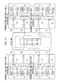
- the 1 ⁇ 4 AWG was used exclusively for the wavelength multiplexer or the wavelength demultiplexing circuit in the prior art, in this embodiment of the present invention the 1 ⁇ 4 AWG is used for the wavelength multi/demultiplexer that performs the wavelength multiplexing and demultiplexing simultaneously.
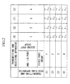
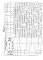
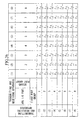
- Fig. 2 is a table showing a periodic wavelength demultiplexing property in input/output combination of the 4 ⁇ 4 AWG and a port connection rule between the transmitting and receiving apparatuses and the 4 ⁇ 4 AWG in this embodiment of the present invention.
- the wavelength demultiplexing property of the 4 ⁇ 4 AWG has the same periodicity as that of the prior art.
- the connection relation between the transmitting and receiving apparatuses and the first I/O port group of the 4 ⁇ 4 AWG is also the same as that of the prior art, the connection relation between the transmitting and receiving apparatuses and the second I/O port group of the 4 ⁇ 4 AWG is different from that of the prior art.
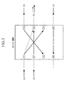
- optical signals input/output bidirectionally.
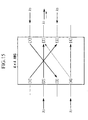
- the WDM wavelength light output from the port of the 4 ⁇ 4 AWG includes only one optical signal and one coherent crosstalk light. For example, as shown in Fig.
- the light having the wavelength ⁇ 3 which is output from the port 2 of the second I/O port group, includes only the optical signal ⁇ 3 (thick solid line) input from the port 2 of the first I/O port group and the crosstalk light (thin solid line) of the optical signal ⁇ 3 input from the port 1 of the first I/O port group, and does not include the crosstalk lights of the optical signals ⁇ 3 input from the ports 1 and 4 of the second I/O port group.
- the accumulation number of the coherent crosstalk lights is reduced to one from three, which is the accumulation number in the prior art.
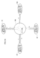
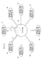
- Fig. 4 is a diagram for explaining wavelength addressing in this embodiment.
- reference numerals 81 to 84 denote four transmitting and receiving apparatuses
- reference numeral 85 denotes a 4 ⁇ 4 AWG.
- the wavelength demultiplexing property of the 4 ⁇ 4 AWG 85 and the connection relation between the transmitting and receiving apparatuses and the 4 ⁇ 4 AWG 85 are explained in Fig. 2.
- the optical signal having the wavelength ⁇ 4 transmitted from the transmitting and receiving apparatus (1) 81, is guided to the port 3 ofthe second I/O port group in the 4 ⁇ 4 AWG 85, and switched within the 4 ⁇ 4 AWG 85.
- This optical signal is then sent to the transmitting and receiving apparatus (2) 82 from the port 2 of the first I/O port group.
- the return signal ⁇ 2 returned from the transmitting and receiving apparatus (2) 82 is guided to the port 2 of the second I/O port group in the 4 ⁇ 4 AWG 85, and then sent to the transmitting and receiving apparatus (1) 81 from the port 1 of the first I/O port group.
- one of the two optical signals having the wavelength ⁇ 1 returned from the transmitting and receiving apparatus (1) 81 is guided to the port 3 of the second I/O port group in the 4 ⁇ 4 AWG 85, and automatically delivered to the transmitting and receiving apparatus (3) 83 from the port 3 of the first I/O port group.
- the other is guided to the port 1 of the first I/O port group in the 4 ⁇ 4 AWG 85, and automatically delivered to the transmitting and receiving apparatus (4) 84 from the port 1 of the second I/O port group.
- These two optical signals are transmitted from the transmitters 45 and 46 of the transmitting and receiving apparatus (1) 41 in Fig. 1.
- the full-mesh WDM transmission network device in this embodiment uses the constituent components similar to those of the prior art, and keeps the similar wavelength addressing function, while reducing the accumulation number of the coherent crosstalk lights included in each WDM wavelength light to one from three, thus realizing higher quality communication. Specifically, the S/N of the received light is improved by 3 dB.
- the port 1 of the first I/O port group is connected to the transmitting and receiving apparatus (1), and the port 2 is connected to the transmitting and receiving apparatus (2).
- the port 3 is connected to the transmitting and receiving apparatus (3), and the port 4 is connected to the transmitting and receiving apparatus (4).
- each port of the second I/O port group and the transmitting and receiving apparatuses (1) to (4) are connected as follows: For the cases 1 and 2.
- the ports of the second I/O port group and the transmitting and receiving apparatuses (1) to (4) are connected in any one of the following manners:
- the number of the port combinations through which the optical signals are transmitted from the first I/O port group to the second I/O port group are made to be equal to that ofthe port combinations through which the optical signals are transmitted from the second I/O port group to the first I/O port group, that is, N/2.
- N/2 the number of the port combinations through which the optical signals are transmitted from the second I/O port group to the first I/O port group.
- Fig. 5 is a block diagram for explaining a second embodiment of the present invention, which shows a schematic constitution of the full-mesh WDM transmission network device in which the number N is increased to eight from four in the first embodiment.
- the 8 ⁇ 8 wavelength multi/demultiplexer 98 is connected to the eight transmitting and receiving apparatuses, illustrations for the seven transmitting and receiving apparatuses other than the transmitting and receiving apparatus (1) 91 are omitted.
- a 1 ⁇ 8 AWG was used as the 1 ⁇ 8 wavelength multi/demultiplexers 96 and 97, and an 8 ⁇ 8 AWG having a periodic wavelength demultiplexing property in input/output combination was used as the 8 ⁇ 8 wavelength multi/demultiplexer 98.
- Constituent components including the transmitter, the receiver, the 1 ⁇ 8 AWG, the 8 ⁇ 8 AWG and the optical fiber, which constitute the full-mesh WDM transmission network device of this embodiment, are identical to those ofthe prior art.
- this embodiment of the present invention uses the 1 ⁇ 8 AWG for the wavelength multi/demultiplexer that performs the wavelength multiplexing and demultiplexing simultaneously, similarly to the first embodiment.
- Fig. 6 is a table showing a periodic wavelength demultiplexing property in input/output combination of the 8 ⁇ 8 AWG and a port connection rule between the transmitting and receiving apparatuses and the 8 ⁇ 8 AWG in this embodiment of the present invention.
- the wavelength demultiplexing property of the 8 ⁇ 8 AWG is the same as that of the prior art
- the connection relation between the transmitting and receiving apparatuses and the second I/O port group of the 8 ⁇ 8 AWG is different from that of the prior art, similarly to the first embodiment.
- the 8 ⁇ 8 AWG performs bi-directional input/output for the optical signals.
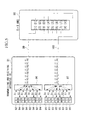
- the four optical signals among the eight optical signals having the equal wavelength are input from the first I/O port group side to the 8 ⁇ 8 AWG, and other four optical signals are input from the second I/O port group side thereto. Since lightwaves which are traveling in opposite directions are independent from each other, a predetermined WDM wavelength light output from the port of the AWG includes only one optical signal and three coherent crosstalk lights. For example, as shown in Fig.
- the light having the wavelength ⁇ 3 which is output from the port 2 of the second I/O port group, includes only the optical signal ⁇ 3 (thick solid line) input from the port 2 of the first I/O port group and the crosstalk lights (thin solid line) of the optical signals ⁇ 3 input from the ports 1, 5 and 6 of the first I/O port group, and does not include the crosstalk lights of the optical signals ⁇ 3 input from the ports 1, 4, 5 and 8 of the second I/O port group.
- the accumulation number of the coherent crosstalk lights is reduced to three from seven that is the accumulation number in the prior art.
- the four optical signals having the equal wavelength, which are input from the first I/O port group side are input from the ports 1, 2, 5 and 6 or the ports 3, 4, 7 and 8 and the four optical signals having the equal wavelength, which are input from the second I/O port group side, are input from the ports 1, 4, 5 and 8 or the ports 2, 3, 6 and 7, respectively, three coherent crosstalk lights included in the output WDM wavelength light are one adjacent crosstalk light and two non-adjacent crosstalk lights. Accordingly, in the full-mesh WDM transmission network device of this embodiment, the S/N of the WDM wavelength light received is expressed as follows.
- S/N P Signal /[P AdjCT + 2P OthCT ]
- the S/N is equal to 29dB when P AdjCT /P Signal is assumed to be -30dB and P OthCT /P Signal is assumed to be -40dB, respectively, and the S/N is improved by 3dB compared to 26dB in the prior art.
- Fig. 8 is a diagram for explaining wavelength addressing in this embodiment.
- reference numerals 101 to 108 denote eight transmitting and receiving apparatuses
- reference numeral 109 denotes an 8 ⁇ 8 AWG.
- the wavelength demultiplexing property of the 8 ⁇ 8 AWG and the connection relation between the transmitting and receiving apparatuses and the 8 ⁇ 8 AWG are explained in Fig. 6.
- the optical signal having the wavelength ⁇ 6 transmitted from the transmitting and receiving apparatus (1) 101, is guided to the port 5 of the second I/O port group in the 8 ⁇ 8 AWG, and switched within the 8 ⁇ 8 AWG 109.
- This optical signal is then sent to the transmitting and receiving apparatus (2) 102 from the port 2 of the first I/O port group.
- the return signal ⁇ 4 transmitted from the transmitting and receiving apparatus (2) 102 is guided to the port 4 of the second I/O port group in the 8 ⁇ 8 AWG 109, and then sent to the transmitting and receiving apparatus (1)101 from the port 1 of the first I/O port group.
- the optical signals having the wavelengths ⁇ 5 and ⁇ 7 , transmitted from the transmitting and receiving apparatus (1) 101 are automatically delivered to the transmitting and receiving apparatus (5) 105 and the transmitting and receiving apparatus (3) 103, respectively.
- the full-mesh WDM transmission network device in this embodiment uses the constituent components similar to those of the prior art, and keeps the similar wavelength addressing function, while reducing the accumulation number ofthe coherent crosstalk lights included in each WDM wavelength light to three from seven, thus realizing higher quality communication. Specifically, the S/N of the received light is improved by 3 dB.
- Fig. 9 is a block diagram for explaining a third embodiment of the present invention, which shows a schematic constitution of the full-mesh WDM transmission network device in which the number N is increased to 16 compared to the first and the second embodiments.
- the 16 ⁇ 16 wavelength multi/demultiplexer 118 is connected to the sixteen transmitting and receiving apparatuses, illustrations for the fifteen transmitting and receiving apparatuses other than the transmitting and receiving apparatus (1) 111 are omitted.
- a 1 ⁇ 16 AWG was used as the 1 ⁇ 16 wavelength multi/demultiplexers 116 and 117, and a 16 ⁇ 16 AWG having a periodic wavelength demultiplexing property in input/output combination was used as the 16 ⁇ 16 wavelength multi/demultiplexer 118.
- Constituent components including the transmitter, the receiver, the 1 ⁇ 16 AWG, the 16 ⁇ 16 AWG and the optical fiber, which constitute the full-mesh WDM transmission network device of this embodiment, are identical to those of the prior art.
- this embodiment of the present invention uses the 1 ⁇ 16 AWG for the wavelength multi/demultiplexer that performs the wavelength multiplexing and demultiplexing simultaneously, similarly to the first and second embodiments.
- Fig. 10 is a table showing a periodic wavelength demultiplexing property in input/output combination of the 16 ⁇ 16 AWG and a port connection rule between the transmitting and receiving apparatuses and the 16 ⁇ 16 AWG in this embodiment of the present invention
- the wavelength demultiplexing property of the 16 ⁇ 16 AWG is the same as that of the prior art
- the port connection rule between the transmitting and receiving apparatuses and the second I/O port group ofthe 16 ⁇ 16 AWG is different from that ofthe prior art, similarly to the first and second embodiments.
- the 16 ⁇ 16 AWG performs bi-directional input/output for the optical signals.
- the eight optical signals among the sixteen optical signals having the equal wavelength are input from the first I/O port group side to the 16 ⁇ 16 AWG, and other eight optical signals are input from the second I/O port group side thereto. Since lightwaves which are traveling in opposite directions are independent from each other, a predetermined WDM wavelength light output from the port of the AWG includes only one optical signal and seven coherent crosstalk lights. For example, as shown in Fig.
- the light having the wavelength ⁇ 3 which is output from the port 2 of the second I/O port group, includes only the optical signal ⁇ 3 (thick solid line) input from the port 2 of the first I/O port group and the crosstalk lights (thin solid line) of the optical signals ⁇ 3 input from the ports 1, 5, 6, 9, 10, 13, and 14 of the first I/O port group, and does not include the crosstalk lights of the optical signals ⁇ 3 input from the ports 1, 4, 5, 8, 9, 12, 13, and 16 of the second I/O port group.
- the accumulation number of the coherent crosstalk lights is reduced to seven from fifteen that is the accumulation number in the prior art.
- the eight optical signals having the equal wavelength, which are input from the first I/O port group side are input from the ports 1, 2, 5, 6, 9, 10, 13, and 14 or the ports 3, 4, 7, 8, 11, 12, 15, and 16 and the eight optical signals having the equal wavelength, which are input from the second I/O port group side, are input from the ports 1, 4, 5, 8, 9, 12, 13, and 16 or the ports 2, 3, 6, 7, 10, 11, 14, and 15, seven coherent crosstalk lights included in the output WDM wavelength light are one adjacent crosstalk light and six non-adjacent crosstalk lights.
- the S/N is equal to 28dB when P AdjCT /P Signal is assumed to be -30dB and P OthCT /P Signal is assumed to be -40dB, respectively, and the S/N is improved by 3dB compared to 25dB in the prior art.
- Fig. 12 is a diagram for explaining wavelength addressing in this embodiment.
- reference numerals 121 to 136 denote sixteen transmitting and receiving apparatuses
- reference numeral 137 denotes a 16 ⁇ 16 AWG.
- the wavelength demultiplexing property of the 16 ⁇ 16 AWG and the connection relation between the transmitting and receiving apparatuses and the 16 ⁇ 16 AWG are explained in Fig. 10.
- the optical signal having the wavelength ⁇ 10 transmitted from the transmitting and receiving apparatus (1) 121, is guided to the port 9 of the second I/O port group in the 16 ⁇ 16 AWG 137, and switched within the 16 ⁇ 16 AWG 137.
- This optical signal is then sent to the transmitting and receiving apparatus (2) 122 from the port 2 of the first I/O port group.
- the return signal ⁇ 8 transmitted from the transmitting and receiving apparatus (2) 122 is guided to the port 8 ofthe second I/O port group in the 16 ⁇ 16 AWG 137, and then sent to the transmitting and receiving apparatus (1) 121 from the port 1 of the first I/O port group.
- the optical signals having the wavelengths ⁇ 6 and ⁇ 9 , transmitted from the transmitting and receiving apparatus (1) 121 for example, are automatically delivered to the transmitting and receiving apparatus (6) 126 and the transmitting and receiving apparatus (9) 129, respectively.
- the full-mesh WDM transmission network device in this embodiment uses the constituent components similar to those of the prior art, and keeps the similar wavelength addressing function, while reducing the accumulation number of the coherent crosstalk lights included in each WDM wavelength light to seven from fifteen, thus realizing higher quality communication. Specifically, the S/N of the received light is improved by 3 dB.
- Fig. 13 is a block diagram for explaining a fourth embodiment of the present invention, which shows a schematic constitution of a full-mesh WDM transmission network device having a different connection constitution from that of the first embodiment, in which the number N is four. Referring to Fig.
- the 1 ⁇ 4 AWG was conventionally used exclusively for the wavelength multiplexer or the wavelength demultiplexing circuit, in this embodiment of the present invention the 1 ⁇ 4 AWG is used for the wavelength multi/demultiplexer which performs the wavelength multiplexing and demultiplexing simultaneously, similarly to the first to third embodiments.
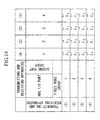
- Fig. 14 is a table showing a periodic wavelength demultiplexing property in input/output combination of the 4 ⁇ 4 AWG and a port connection rule between the transmitting and receiving apparatuses and the 4 ⁇ 4 AWG in this embodiment.
- the wavelength demultiplexing property of the 4 ⁇ 4 AWG has the same periodicity as that of the prior art.
- the connection relation between the transmitting and receiving apparatuses and the second I/O port group of the 4 ⁇ 4 AWG is different from that of the prior art, similarly to the first to third embodiments.
- a bi-directional input/output ofthe optical signal is performed.
- a predetermined WDM wavelength light output from the port of the 4 ⁇ 4 AWG includes only one optical signal and one coherent crosstalk light. For example, as shown in Fig.
- the light having the wavelength ⁇ 3 which is output from the port 2 of the second I/O port group, includes only the optical signal ⁇ 3 (thick solid line) input from the port 2 of the first I/O port group and the crosstalk light (thin solid line) of the optical signal ⁇ 3 input from the port 4 of the first I/O port group, and does not include the crosstalk lights of the optical signals ⁇ 3 input from the ports 1 and 3 of the second I/O port group. Specifically, the accumulation number of the coherent crosstalk lights is reduced to one from three, which is the accumulation number in the prior art.
- the S/N of the WDM wavelength light received is expressed as follows.
- S/N P Signal /P OthCT
- the S/N is equal to 40dB when P otheCT /P signal , is assumed to be - 40dB, and the S/N is improved by 13dB compared to 27dB ofthe prior art.
- Fig. 16 is a diagram for explaining wavelength addressing in this embodiment.
- reference numerals 181 to 184 denote four transmitting and receiving apparatuses
- reference numeral 185 denotes a 4 ⁇ 4 AWG.
- the wavelength demultiplexing property of the 4 ⁇ 4 AWG and the connection relation between the transmitting and receiving apparatuses and the 4 ⁇ 4 AWG are explained in Fig. 14.
- one optical signal having the wavelength ⁇ 1 transmitted from the transmitting and receiving apparatus (1) 181 is guided to the port 4 of the second I/O port group in the 4 ⁇ 4 AWG 185, and switched within the 4 ⁇ 4 AWG 185.
- This optical signal is then sent to the transmitting and receiving apparatus (2) 182 from the port 2 of the first I/O port group.
- the return signal ⁇ 2 returned from the transmitting and receiving apparatus (2) 182 is guided to the port 3 of the second I/O port group in the 4 ⁇ 4 AWG 185, and then sent to the transmitting and receiving apparatus (1) 181 from the port 1 of the first I/O port group.
- the other optical signal having the wavelength ⁇ 1 and one optical signal having the wavelength ⁇ 2 which are transmitted from the transmitting and receiving apparatus (1) 181, are automatically delivered to the transmitting and receiving apparatuses (4) 184 and (3) 183, respectively.
- the full-mesh WDM transmission network device in this embodiment uses the constituent components similar to those of the prior art, and maintains the same wavelength addressing function, while reducing the accumulation number ofthe coherent crosstalk lights included in each WDM wavelength light to one from three, thus realizing higher quality communication. Specifically, the S/N of the received light is improved by 13 dB.
- the port 1 of the first I/O port group is connected to the transmitting and receiving apparatus (1), and the port 2 is connected to the transmitting and receiving apparatus (2).
- the port 3 is connected to the transmitting and receiving apparatus (3), and the port 4 is connected to the transmitting and receiving apparatus (4).
- Direction of the optical signal in each column of the table will be any one of the following cases 1 to 4.
- the ports of the second I/O port group and the transmitting and receiving apparatuses (1) to (4) are connected in any one of the following manners.
- the table is completed by the above-described ways (1) to (3).
- the table completed in such ways satisfies the following condition 6 ⁇ in addition to the conditions 1 ⁇ to 5 ⁇ described in the first embodiment.
- N is four. 6 ⁇
- the wavelengths of all the optical signals transmitted from any one of the ports of one I/O port group to the other I/O port group are different from a wavelength of any optical signal transmitted from a port adjacent to the said one port toward the other I/O port group.
- Fig. 17 is a block diagram for explaining a fifth embodiment of the present invention, which shows a schematic constitution of a full-mesh WDM transmission network device in which the number N is increased to eight compared to the fourth embodiment.
- the 8 ⁇ 8 wavelength multi/demultiplexer 198 is connected to the eight transmitting and receiving apparatuses, illustrations for the seven transmitting and receiving apparatuses other than the transmitting and receiving apparatus (1) 191 are omitted.
- the 1 ⁇ 8 AWG was conventionally used exclusively for the wavelength multiplexer or the wavelength demultiplexing circuit, in this embodiment the 1 ⁇ 8 AWG is used as the wavelength multi/demultiplexer which performs the wavelength multiplexing and demultiplexing simultaneously, similarly to the first to fourth embodiments.
- Fig. 18 is a table showing a periodic wavelength demultiplexing property in input/output combination of the 8 ⁇ 8 AWG and a port connection rule between the transmitting and receiving apparatuses and the 8 ⁇ 8 AWG in this embodiment.
- the wavelength demultiplexing property of the 8 ⁇ 8 AWG has the same periodicity as that of the prior art.
- the connection relation between the transmitting and receiving apparatuses and the second I/O port group of the 4 ⁇ 4 AWG is different from that of the prior art, similarly to the first to third embodiments.
- a bi-directional input/output ofthe optical signal is performed.
- the four optical signals among the eight optical signals having the equal wavelength are input from the first I/O port group side to the 8 ⁇ 8 AWG, and other four optical signals are input from the second I/O port group side thereto. Since lightwaves which are traveling in opposite directions are independent from each other, a predetermined WDM wavelength light output from the port of the 8 ⁇ 8 AWG includes only one optical signal and three coherent crosstalk lights. For example, as shown in Fig.
- the light having the wavelength ⁇ 3 which is output from the port 2 of the second I/O port group, includes only the optical signal ⁇ 3 (thick solid line) input from the port 2 of the first I/O port group and the crosstalk lights (thin solid line) of the optical signals ⁇ 3 input from the ports 4, 6, and 8 of the first I/O port group, and does not include the crosstalk lights of the optical signals ⁇ 3 input from the ports 1, 3, 5, and 7 of the second I/O port group.
- the accumulation number of the coherent crosstalk lights is reduced to three from seven that is the accumulation number in the prior art.
- Fig. 20 is a diagram for explaining wavelength addressing in this embodiment.
- reference numerals 201 to 208 denote eight transmitting and receiving apparatuses
- reference numeral 209 denotes an 8 ⁇ 8 AWG.
- the wavelength demultiplexing property of the 8 ⁇ 8 AWG and the connection relation between the transmitting and receiving apparatuses and the ports of the 8 ⁇ 8 AWG are explained in Fig. 18.
- one optical signal having the wavelength ⁇ 1 transmitted from the transmitting and receiving apparatus (1) 201 is guided to port 8 of the second I/O port group of the 8 ⁇ 8 AWG 209, and switched within the 8 ⁇ 8 AWG 209.
- This optical signal is then sent to the transmitting and receiving apparatus (2) 202 from the port 2 of the first I/O port group.
- the return signal ⁇ 7 returned from the transmitting and receiving apparatus (2) 202 is guided to the port 7 of the second I/O port group in the 8 ⁇ 8 AWG 209, and then sent to the transmitting and receiving apparatus (1) 201 from the port 1 of the first I/O port group.
- the optical signals having the wavelengths ⁇ 4 and ⁇ 6 which are transmitted from the transmitting and receiving apparatus (1) 201, for example, are automatically delivered to the transmitting and receiving apparatuses (5) 205 and (3) 203, respectively.
- the full-mesh WDM transmission network device in this embodiment uses the constituent components similar to those of the prior art, and keeps the similar wavelength addressing function, while reducing the accumulation number of the coherent crosstalk lights included in each WDM wavelength light to three from seven, thus realizing higher quality communication. Specifically, the S/N of the received light is improved by 9 dB.
- Fig. 21 is a block diagram for explaining a sixth embodiment of the present invention, which shows a schematic constitution of a full-mesh WDM transmission network device in which the number N is increased to sixteen compared to the fourth and fifth embodiments.
- the 16 ⁇ 16 wavelength multi/demultiplexer 218 is connected to the sixteen transmitting and receiving apparatuses, illustrations for the fifteen transmitting and receiving apparatuses other than the transmitting and receiving apparatus (1) 211 are omitted.
- the 1 ⁇ 16 AWG was conventionally used exclusively for the wavelength multiplexer or the wavelength demultiplexing circuit, in this embodiment the 1 ⁇ 16 AWG is used as the wavelength multi/demultiplexer which performs the wavelength multiplexing and demultiplexing simultaneously, similarly to the first to fifth embodiments.
- Fig. 22 is a table showing a periodic wavelength demultiplexing property in input/output combination of the 16 ⁇ 16 AWG and a port connection rule between the transmitting and receiving apparatuses and the 16 ⁇ 16 AWG in this embodiment.
- the wavelength demultiplexing property ofthe 16 ⁇ 16 AWG has the same periodicity as that of the prior art.
- the connection relation between the transmitting and receiving apparatuses and the second I/O port group of the 16 X 16 AWG is different from that of the prior art, similarly to the first to fifth embodiments.
- a bi-directional input/output of the optical signal is performed.
- a predetermined WDM wavelength light output from the port of the 16 ⁇ 16 AWG includes only one optical signal and seven coherent crosstalk lights. For example, as shown in Fig.
- the light having the wavelength ⁇ 3 which is output from the port 2 of the second I/O port group, includes only the optical signal ⁇ 3 (thick solid line) input from the port 2 ofthe first I/O port group and the crosstalk lights (thin solid line) of the optical signals ⁇ 3 input from the ports 4, 6, 8, 10, 12, 14, and 16 of the first I/O port group, and does not include the crosstalk lights of the optical signals ⁇ 3 input from the ports 1, 3, 5, 7, 9, 11, 13, and 15 of the second I/O port group.
- the accumulation number of the coherent crosstalk lights is reduced to seven from fifteen that is the accumulation number in the prior art.
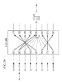
- Fig. 24 is a diagram for explaining wavelength addressing in this embodiment.
- reference numerals 221 to 236 denote sixteen transmitting and receiving apparatuses
- reference numeral 237 denotes a 16 ⁇ 16 AWG.
- the wavelength demultiplexing property of the 16 ⁇ 16 AWG and the connection relation between the transmitting and receiving apparatuses and the ports ofthe 16 ⁇ 16 AWG are explained in Fig. 22.
- one optical signal having the wavelength ⁇ 1 transmitted from the transmitting and receiving apparatus (1) 221 is guided to the port 16 of second I/O port group of the 16 ⁇ 16 AWG 237, and switched within the 16 ⁇ 16 AWG 237.
- This optical signal is then sent to the transmitting and receiving apparatus (2) 222 from the port 2 of the first I/O port group.
- the return signal ⁇ 15 returned from the transmitting and receiving apparatus (2) 222 is guided to the port 15 of the second I/O port group in the 16 ⁇ 16 AWG 237, and then sent to the transmitting and receiving apparatus (1) 221 from the port 1 of the first I/O port group.
- the optical signals having the wavelengths ⁇ 8 and ⁇ 11 which are transmitted from the transmitting and receiving apparatus (1) 221, for example, are automatically delivered to the transmitting and receiving apparatuses (9) 229 and (6) 226, respectively.
- the full-mesh WDM transmission network device in this embodiment uses the constituent components similar to those of the prior art, and maintains the same wavelength addressing function, while reducing the accumulation number of the coherent crosstalk lights included in each WDM wavelength light to seven from fifteen, thus realizing higher quality communication. Specifically, the S/N ofthe received light is improved by 7 dB.
- the full-mesh optical wavelength division multiplexing transmission network device of the present invention in which N is 4, 8 and 16 in six embodiments, was described, as a matter of course, it is possible to constitute the full-mesh optical wavelength division multiplexing transmission network device of the present invention even when N takes any value.
- the connection relation between the transmitting and receiving apparatuses and the ports of the N ⁇ N AWG and the combinations of the transmitting directions of the optical signals between I/O ports in the N ⁇ N AWG are not limited to those illustrated in Figs. 2, 6, 10, 14, 18 and 22. It is apparent that other connection relations and other combinations, by which the operations similar to those of the embodiments can be realized, are within the spirit and scope of the present invention.
Landscapes
- Engineering & Computer Science (AREA)
- Computer Networks & Wireless Communication (AREA)
- Signal Processing (AREA)
- Physics & Mathematics (AREA)
- Electromagnetism (AREA)
- Optical Communication System (AREA)
- Small-Scale Networks (AREA)
- Use Of Switch Circuits For Exchanges And Methods Of Control Of Multiplex Exchanges (AREA)
Abstract
Description
- the optical signal between the
port 1 of the first I/O port group and theport 1 of the second I/O port group - the optical signal between the
port 1 of the first I/O port group and theport 3 of the second I/O port group - the optical signal between the
port 4 of the first I/O port group and theport 1 of the second I/O port group - the optical signal between the
port 4 of the first I/O port group and theport 3 of the second I/O port group - the optical signal between the
port 2 of the first I/O port group and theport 2 of the second I/O port group - the optical signal between the
port 2 of the first I/O port group and theport 4 of the second I/O port group - the optical signal between the
port 3 of the first I/O port group and theport 2 of the second I/O port group - the optical signal between the
port 3 of the first I/O port group and theport 4 of the second I/O port group
- the optical signal between the
port 2 of the first I/O port group and theport 1 of the second I/O port group - the optical signal between the
port 2 of the first I/O port group and theport 3 of the second I/O port group - the optical signal between the
port 3 of the first I/O port group and theport 1 of the second I/O port group - the optical signal between the
port 3 of the first I/O port group and theport 3 of the second I/O port group - the optical signal between the
port 1 of the first I/O port group and theport 2 of the second I/O port group - the optical signal between the
port 1 of the first I/O port group and theport 4 of the second I/O port group - the optical signal between the
port 4 of the first I/O port group and theport 2 of the second I/O port group - the optical signal between the
port 4 of the first I/O port group and theport 4 of the second I/O port group
- the optical signal between the
port 1 of the first I/O port group and theport 1 of the second I/O port group - the optical signal between the
port 1 of the first I/O port group and theport 3 of the second I/O port group - the optical signal between the
port 2 of the first I/O port group and theport 1 of the second I/O port group - the optical signal between the
port 2 of the first I/O port group and theport 3 of the second I/O port group - the optical signal between the
port 3 of the first I/O port group and theport 2 of the second I/O port group - the optical signal between the
port 3 of the first I/O port group and theport 4 of the second I/O port group - the optical signal between the
port 4 of the first I/O port group and theport 2 of the second I/O port group - the optical signal between the
port 4 of the first I/O port group and theport 4 of the second I/O port group
- the optical signal between the
port 3 of the first I/O port group and theport 1 of the second I/O port group - the optical signal between the
port 3 of the first I/O port group and theport 3 of the second I/O port group - the optical signal between the
port 4 of the first I/O port group and theport 1 of the second I/O port group - the optical signal between the
port 4 of the first I/O port group and theport 3 of the second I/O port group - the optical signal between the
port 1 of the first I/O port group and theport 2 of the second I/O port group - the optical signal between the
port 1 of the first I/O port group and theport 4 of the second I/O port group - the optical signal between the
port 2 of the first I/O port group and theport 2 of the second I/O port group - the optical signal between the
port 2 of the first I/O port group and theport 4 of the second I/O port group
For the
- The
port 1 of the second I/O port group is connected to the transmitting and receiving apparatus (1), and theport 2 is connected to the transmitting and receiving apparatus (2). Theport 3 is connected to the transmitting and receiving apparatus (4) and theport 4 is connected to the transmitting and receiving apparatus (3). - The
port 1 of the second I/O port group is connected to the transmitting and receiving apparatus (4), and theport 2 is connected to the transmitting and receiving apparatus (2). Theport 3 is connected to the transmitting and receiving apparatus (1) and theport 4 is connected to the transmitting and receiving apparatus (3). - The
port 1 of the second I/O port group is connected to the transmitting and receiving apparatus (1), and theport 2 is connected to the transmitting and receiving apparatus (3). Theport 3 is connected to the transmitting and receiving apparatus (4) and theport 4 is connected to the transmitting and receiving apparatus (2). - The
port 1 of the second I/O port group is connected to the transmitting and receiving apparatus (4), and theport 2 is connected to the transmitting and receiving apparatus (3). Theport 3 is connected to the transmitting and receiving apparatus (1) and theport 4 is connected to the transmitting and receiving apparatus (2). - The
port 1 of the second I/O port group is connected to the transmitting and receiving apparatus (2), and theport 2 is connected to the transmitting and receiving apparatus (1). Theport 3 is connected to the transmitting and receiving apparatus (3) and theport 4 is connected to the transmitting and receiving apparatus (4). - The
port 1 of the second I/O port group is connected to the transmitting and receiving apparatus (3), and theport 2 is connected to the transmitting and receiving apparatus (1). Theport 3 is connected to the transmitting and receiving apparatus (2) and theport 4 is connected to the transmitting and receiving apparatus (4). - The
port 1 of the second I/O port group is connected to the transmitting and receiving apparatus (2), and theport 2 is connected to the transmitting and receiving apparatus (4). Theport 3 is connected to the transmitting and receiving apparatus (3) and theport 4 is connected to the transmitting and receiving apparatus (1). - The
port 1 of the second I/O port group is connected to the transmitting and receiving apparatus (3), and theport 2 is connected to the transmitting and receiving apparatus (4). Theport 3 is connected to the transmitting and receiving apparatus (2) and theport 4 is connected to the transmitting and receiving apparatus (1).
- The
port 1 of the second I/O port group is connected to the transmitting and receiving apparatus (1), and theport 2 is connected to the transmitting and receiving apparatus (3). Theport 3 is connected to the transmitting and receiving apparatus (2) and theport 4 is connected to the transmitting and receiving apparatus (4). - The
port 1 of the second I/O port group is connected to the transmitting and receiving apparatus (2), and theport 2 is connected to the transmitting and receiving apparatus (3). Theport 3 is connected to the transmitting and receiving apparatus (1) and theport 4 is connected to the transmitting and receiving apparatus (4). - The
port 1 of the second I/O port group is connected to the transmitting and receiving apparatus (1), and theport 2 is connected to the transmitting and receiving apparatus (4). Theport 3 is connected to the transmitting and receiving apparatus (2) and theport 4 is connected to the transmitting and receiving apparatus (3). - The
port 1 of the second I/O port group is connected to the transmitting and receiving apparatus (2), and theport 2 is connected to the transmitting and receiving apparatus (4). Theport 3 is connected to the transmitting and receiving apparatus (1) and theport 4 is connected to the transmitting and receiving apparatus (3). - The
port 1 of the second I/O port group is connected to the transmitting and receiving apparatus (3), and theport 2 is connected to the transmitting and receiving apparatus (1). Theport 3 is connected to the transmitting and receiving apparatus (4) and theport 4 is connected to the transmitting and receiving apparatus (2). - The
port 1 of the second I/O port group is connected to the transmitting and receiving apparatus (4), and theport 2 is connected to the transmitting and receiving apparatus (1). Theport 3 is connected to the transmitting and receiving apparatus (3) and theport 4 is connected to the transmitting and receiving apparatus (2). - The
port 1 of the second I/O port group is connected to the transmitting and receiving apparatus (3), and theport 2 is connected to the transmitting and receiving apparatus (2). Theport 3 is connected to the transmitting and receiving apparatus (4) and theport 4 is connected to the transmitting and receiving apparatus (1). - The
port 1 of the second I/O port group is connected to the transmitting and receiving apparatus (4), and theport 2 is connected to the transmitting and receiving apparatus (2). Theport 3 is connected to the transmitting and receiving apparatus (3) and theport 4 is connected to the transmitting and receiving apparatus (1).
- 1 ○ The
ports 1 to N of the first I/O port group are connected to different transmitting and receiving apparatuses among the transmitting and receiving apparatuses (1) to (N), respectively. Moreover, theports 1 to N of the second I/O port group are connected to different transmitting and receiving apparatuses among the transmitting and receiving apparatuses (1) to (N), respectively. - 2 ○ The input/output combinations between the first and second I/O port groups have the periodic wavelength demultiplexing property. To be more specific, each of N optical signals, which has a different wavelength from the others, is transmitted at each ofN paths between any one of the ports of the first I/O port group and N ports of the second I/O port group. Moreover, each of N optical signals, which has a different wavelength from the others, is transmitted at each ofN paths between any one of the ports of the second I/O port group and N ports of the first I/O port group. As a result, among N × N port combinations made by the N ports of the first I/O port group and the N ports of the second I/O port group, there are N port combinations for each wavelength, through which optical signals having the same wavelength are transmitted.
- 3 ○ Among the N port combinations made by any one of the ports of the first I/O port group and each port of the second I/O port group, the optical signals are transmitted from the first I/O port group to the second I/O port group through the N/2 port combinations, and the optical signals are transmitted from the second I/O port group to the first I/O port group through the remaining port combinations.
- 4 ○ Among the N port combinations through which optical signals having an equal wavelength are transmitted, the optical signals are transmitted from the first I/O port group to the second I/O port group through the N/2 port combinations, and the optical signals are transmitted from the second I/O port group to the first I/O port group through the remaining port combinations.
- 5 ○ The ports of the second I/O port group to which the optical signals are transmitted from the ports of the first I/O port group connected to any one of the transmitting and receiving apparatuses and the ports of the first I/O port group to which the optical signals are transmitted from the ports of the second I/O port group connected to this transmitting and receiving apparatus are respectively connected to different transmitting and receiving apparatuses.
- the optical signal between the
port 1 of the first I/O port group and theport 1 of the second I/O port group - the optical signal between the
port 1 of the first I/O port group and theport 2 of the second I/O port group - the optical signal between the
port 2 of the first I/O port group and theport 2 of the second I/O port group - the optical signal between the
port 2 of the first I/O port group and theport 3 of the second I/O port group - the optical signal between the
port 3 of the first I/O port group and theport 3 of the second I/O port group - the optical signal between the
port 3 of the first I/O port group and theport 4 of the second I/O port group - the optical signal between the
port 4 of the first I/O port group and theport 4 of the second I/O port group - the optical signal between the
port 4 of the first I/O port group and theport 1 of the second I/O port group
- the optical signal between the
port 1 of the first I/O port group and theport 4 of the second I/O port group - the optical signal between the
port 1 of the first I/O port group and theport 1 of the second I/O port group - the optical signal between the
port 2 of the first I/O port group and theport 1 of the second I/O port group - the optical signal between the
port 2 of the first I/O port group and theport 2 of the second I/O port group - the optical signal between the
port 3 of the first I/O port group and theport 2 of the second I/O port group - the optical signal between the
port 3 of the first I/O port group and theport 3 of the second I/O port group - the optical signal between the
port 4 of the first I/O port group and theport 3 of the second I/O port group - the optical signal between the
port 4 of the first I/O port group and theport 4 of the second I/O port group
- the optical signal between the
port 1 of the first I/O port group and theport 3 of the second I/O port group - the optical signal between the
port 1 of the first I/O port group and theport 4 of the second I/O port group - the optical signal between the
port 2 of the first I/O port group and theport 4 of the second I/O port group - the optical signal between the
port 2 of the first I/O port group and theport 1 of the second I/O port group - the optical signal between the
port 3 of the first I/O port group and theport 1 of the second I/O port group - the optical signal between the
port 3 of the first I/O port group and theport 2 of the second I/O port group - the optical signal between the
port 4 of the first I/O port group and theport 2 of the second I/O port group - the optical signal between the
port 4 of the first I/O port group and theport 3 of the second I/O port group
- the optical signal between the
port 1 of the first I/O port group and theport 2 of the second I/O port group - the optical signal between the
port 1 of the first I/O port group and theport 3 of the second I/O port group - the optical signal between the
port 2 of the first I/O port group and theport 3 of the second I/O port group - the optical signal between the
port 2 of the first I/O port group and theport 4 of the second I/O port group - the optical signal between the
port 3 of the first I/O port group and theport 4 of the second I/O port group - the optical signal between the
port 3 of the first I/O port group and theport 1 of the second I/O port group - the optical signal between the
port 4 of the first I/O port group and theport 1 of the second I/O port group - the optical signal between the
port 4 of the first I/O port group and theport 2 of the second I/O port group
- The
port 1 ofthe second I/O port group is connected to the transmitting and receiving apparatus (4), and theport 2 is connected to the transmitting and receiving apparatus (3). Theport 3 is connected to the transmitting and receiving apparatus (2) and theport 4 is connected to the transmitting and receiving apparatus (1). - The
port 1 of the second I/O port group is connected to the transmitting and receiving apparatus (3), and theport 2 is connected to the transmitting and receiving apparatus (2). Theport 3 is connected to the transmitting and receiving apparatus (1) and theport 4 is connected to the transmitting and receiving apparatus (4). - The
port 1 of the second I/O port group is connected to the transmitting and receiving apparatus (2), and theport 2 is connected to the transmitting and receiving apparatus (1). Theport 3 is connected to the transmitting and receiving apparatus (4) and theport 4 is connected to the transmitting and receiving apparatus (3). - The
port 1 of the second I/O port group is connected to the transmitting and receiving apparatus (1), and theport 2 is connected to the transmitting and receiving apparatus (4). Theport 3 is connected to the transmitting and receiving apparatus (3) and theport 4 is connected to the transmitting and receiving apparatus (2).
6 ○ The wavelengths of all the optical signals transmitted from any one of the ports of one I/O port group to the other I/O port group, are different from a wavelength of any optical signal transmitted from a port adjacent to the said one port toward the other I/O port group.
Claims (4)
- An optical wavelength division multiplexing transmission network device; comprising N transmitting and receiving apparatuses; and an N × N wavelength multi/demultiplexer having a first I/O port group composed of N ports, each of which is connected to each different one of said N transmitting and receiving apparatuses and a second I/O port group composed of N ports, each of which is connected to each different one of said N transmitting and receiving apparatuses,wherein each of N optical signals, which has a different wavelength from the others, is transmitted at each of N paths between any one of the ports of the first I/O port group and N ports of the second I/O port group,each of N optical signals, which has a different wavelength from the others, is transmitted at each of N paths between any one of the ports of the second I/O port group and N ports of the first I/O port group,N port combinations for transmitting optical signals having an equal wavelength exists for each wavelength among N × N port combinations made by the N ports of the first I/O port group and the N ports of the second I/O port group,among the N port combinations for transmitting the optical signals having the equal wavelength, in M port combinations the optical signals are transmitted from the first I/O port group to the second I/O port group, and in N-M port combinations the optical signals are transmitted from the second I/O port group to the first I/O port group, andthe port of the second I/O port group to which the optical signal is transmitted from the port of the first I/O port group connected to the any one of the transmitting and receiving apparatuses and the port ofthe first I/O port group to which the optical signal is transmitted from the port of the second I/O port group connected to the any one of the transmitting and receiving apparatuses are connected to the different transmitting and receiving apparatus.
- The optical wavelength division multiplexing transmission network device according to claim 1, wherein N is an even number and M is equal to N/2.
- The optical wavelength division multiplexing transmission network device according to any one of claims 1 and 2, wherein wavelengths of all optical signals transmitted from any one of the ports of one I/O port group to the other I/O port group are different from those of all optical signals transmitted from a port adjacent to the said one port of the one I/O port group to the other I/O port group.
- The optical wavelength division multiplexing transmission network device according to any one of claims 1, 2 and 3,
wherein said transmitting and receiving apparatus includes:N-M transmitters;M receivers;a 1 × N wavelength multi/demultiplexer which demultiplexes an optical signal output from predetermined one port of the first I/O port group into M optical signals having different wavelengths, inputs the demultiplexed optical signals to the different receivers among the M receivers, multiplexes optical signals output from said N-M transmitters to one optical signal, and transmits the multiplexed optical signal to predetermined one port of the first I/O port group;M transmitters;N-M receivers; anda 1 × N wavelength multi/demultiplexer which demultiplexes an optical signal output from predetermined one port ofthe second I/O port group into N-M optical signals having different wavelengths, inputs the demultiplexed optical signals to the different receivers among the N-M receivers, multiplexes optical signals output from said M transmitters into one optical signal, and transmits the multiplexed optical signal to predetermined one port of the first I/O port group.
Applications Claiming Priority (2)
| Application Number | Priority Date | Filing Date | Title |
|---|---|---|---|
| JP22917499A JP3439162B2 (en) | 1999-08-13 | 1999-08-13 | Optical wavelength division multiplexing network equipment |
| JP22917499 | 1999-08-13 |
Publications (3)
| Publication Number | Publication Date |
|---|---|
| EP1076471A2 true EP1076471A2 (en) | 2001-02-14 |
| EP1076471A3 EP1076471A3 (en) | 2007-05-23 |
| EP1076471B1 EP1076471B1 (en) | 2012-12-12 |
Family
ID=16887959
Family Applications (1)
| Application Number | Title | Priority Date | Filing Date |
|---|---|---|---|
| EP00402253A Expired - Lifetime EP1076471B1 (en) | 1999-08-13 | 2000-08-09 | Optical wavelength division multiplexing transmission network device |
Country Status (5)
| Country | Link |
|---|---|
| US (1) | US6718140B1 (en) |
| EP (1) | EP1076471B1 (en) |
| JP (1) | JP3439162B2 (en) |
| KR (1) | KR100344130B1 (en) |
| CA (1) | CA2315416C (en) |
Cited By (1)
| Publication number | Priority date | Publication date | Assignee | Title |
|---|---|---|---|---|
| CN1745529A (en) * | 2003-02-13 | 2006-03-08 | 日本电信电话株式会社 | Optical communication network system |
Families Citing this family (10)
| Publication number | Priority date | Publication date | Assignee | Title |
|---|---|---|---|---|
| JP4507032B2 (en) * | 2000-02-16 | 2010-07-21 | Kddi株式会社 | Bidirectional wavelength division multiplexing optical communication system |
| EP1271825A1 (en) * | 2001-06-25 | 2003-01-02 | Lucent Technologies Inc. | Method and system for multiplexed optical information transport |
| US7522837B2 (en) | 2002-06-28 | 2009-04-21 | Nippon Telegraph And Telephone Corporation | Optical communication system |
| DE112004000304T5 (en) * | 2003-02-19 | 2007-09-27 | Finisar Corp., Sunnyvale | Module with two bidirectional optical transmitters / receivers |
| JP4291281B2 (en) * | 2005-02-03 | 2009-07-08 | 富士通株式会社 | Information processing system, calculation node, and information processing system control method |
| JP4962918B2 (en) * | 2006-11-30 | 2012-06-27 | 日本電気株式会社 | Wavelength routing system |
| WO2010070709A1 (en) * | 2008-12-18 | 2010-06-24 | 富士通テレコムネットワークス株式会社 | Wavelength division multiplex transmission device for controlling wavelength of fbtl optical module and wavelength control method of wavelength division multiplex transmission device provided with controlling wavelength of fbtl optical module |
| JP2011155481A (en) * | 2010-01-27 | 2011-08-11 | Nippon Telegr & Teleph Corp <Ntt> | Optical wavelength division multiplex communication system |
| US10348437B2 (en) * | 2015-11-18 | 2019-07-09 | Luxtera, Inc. | Method and system for cassette based wavelength division multiplexing |
| US20180109317A1 (en) * | 2016-10-13 | 2018-04-19 | Finisar Corporation | Bi-directional propagation in optical communication |
Family Cites Families (4)
| Publication number | Priority date | Publication date | Assignee | Title |
|---|---|---|---|---|
| US5745612A (en) * | 1995-12-18 | 1998-04-28 | International Business Machines Corporation | Wavelength sorter and its application to planarized dynamic wavelength routing |
| FI103619B1 (en) * | 1997-05-26 | 1999-07-30 | Nokia Telecommunications Oy | Optical multiplexing and demultiplexing |
| KR100237838B1 (en) * | 1997-12-15 | 2000-01-15 | 이계철 | Large capacity optical asynchronous transfer mode switch |
| JP3242369B2 (en) | 1998-07-27 | 2001-12-25 | 日本電信電話株式会社 | Optical multiplexing / demultiplexing circuit |
-
1999
- 1999-08-13 JP JP22917499A patent/JP3439162B2/en not_active Expired - Lifetime
-
2000
- 2000-08-09 US US09/635,526 patent/US6718140B1/en not_active Expired - Lifetime
- 2000-08-09 EP EP00402253A patent/EP1076471B1/en not_active Expired - Lifetime
- 2000-08-10 CA CA002315416A patent/CA2315416C/en not_active Expired - Lifetime
- 2000-08-12 KR KR1020000046800A patent/KR100344130B1/en not_active Expired - Lifetime
Cited By (3)
| Publication number | Priority date | Publication date | Assignee | Title |
|---|---|---|---|---|
| CN1745529A (en) * | 2003-02-13 | 2006-03-08 | 日本电信电话株式会社 | Optical communication network system |
| EP1594241A4 (en) * | 2003-02-13 | 2011-04-27 | Nippon Telegraph & Telephone | OPTICAL COMMUNICATION NETWORK SYSTEM |
| CN1745529B (en) * | 2003-02-13 | 2015-08-19 | 日本电信电话株式会社 | Optical communication network system |
Also Published As
| Publication number | Publication date |
|---|---|
| CA2315416A1 (en) | 2001-02-13 |
| CA2315416C (en) | 2005-10-11 |
| KR20010030087A (en) | 2001-04-16 |
| US6718140B1 (en) | 2004-04-06 |
| KR100344130B1 (en) | 2002-07-20 |
| EP1076471A3 (en) | 2007-05-23 |
| EP1076471B1 (en) | 2012-12-12 |
| JP2001053760A (en) | 2001-02-23 |
| JP3439162B2 (en) | 2003-08-25 |
Similar Documents
| Publication | Publication Date | Title |
|---|---|---|
| US6366378B1 (en) | Optical multiplexing and demultiplexing | |
| US6185023B1 (en) | Optical add-drop multiplexers compatible with very dense WDM optical communication systems | |
| US20090047019A1 (en) | Method and System for Communicating Optical Traffic | |
| KR100334432B1 (en) | Bidirectional add / drop optical amplifier module using one waveguide thermal lattice multiplexer | |
| JP2977024B2 (en) | Optical circuit for wavelength division multiplexing communication and optical transmission communication system including the same | |
| US6348984B1 (en) | Optical add/drop multiplexer | |
| US6452703B1 (en) | Optical add-drop multiplexing technique and wavelength division multiplexing optical link using such a multiplexing technique | |
| US6950609B2 (en) | Tunable, multi-port optical add-drop multiplexer | |
| CA2241707C (en) | Optical drop circuit having group delay compensation | |
| EP1033841A2 (en) | Reconfigurable add/drop for optical fiber communication systems | |
| US6091869A (en) | Low loss, optical add/drop WDM node | |
| EP1076471B1 (en) | Optical wavelength division multiplexing transmission network device | |
| EP1739866A2 (en) | Dynamic allocation of bandwidth in a bidirectional optical transmission system | |
| EP1638232A2 (en) | Optical demultiplexing method and optical multiplexing method, and optical transmission apparatus using same | |
| US6516112B1 (en) | Optical wavelength filter and demultiplexer | |
| US6205269B1 (en) | Optical add/drop multiplexer | |
| US6552834B2 (en) | Methods and apparatus for preventing deadbands in an optical communication system | |
| EP1408713A2 (en) | Optical cross-connect system | |
| EP1109342A2 (en) | Optical demultiplexing/multiplexing device | |
| EP1009120A2 (en) | Multichannel optical ADD/DROP, multiplexor/demultiplexor | |
| US6934474B2 (en) | Bidirectional add/drop multiplexer | |
| EP0967752A2 (en) | WDM transmission system | |
| KR100429042B1 (en) | Bidirectional wavelength division multiplexed self-healing ring network composed of a add fiber and a drop fiber | |
| JP2006050617A (en) | Bidirectional optical add-drop multiplexer | |
| US7133612B1 (en) | Bidirectional WDM transmission system having transmission format for reducing adverse effects of filter concatonation |
Legal Events
| Date | Code | Title | Description |
|---|---|---|---|
| PUAI | Public reference made under article 153(3) epc to a published international application that has entered the european phase |
Free format text: ORIGINAL CODE: 0009012 |
|
| AK | Designated contracting states |
Kind code of ref document: A2 Designated state(s): AT BE CH CY DE DK ES FI FR GB GR IE IT LI LU MC NL PT SE |
|
| AX | Request for extension of the european patent |
Free format text: AL;LT;LV;MK;RO;SI |
|
| PUAL | Search report despatched |
Free format text: ORIGINAL CODE: 0009013 |
|
| AK | Designated contracting states |
Kind code of ref document: A3 Designated state(s): AT BE CH CY DE DK ES FI FR GB GR IE IT LI LU MC NL PT SE |
|
| AX | Request for extension of the european patent |
Extension state: AL LT LV MK RO SI |
|
| 17P | Request for examination filed |
Effective date: 20070712 |
|
| 17Q | First examination report despatched |
Effective date: 20070904 |
|
| AKX | Designation fees paid |
Designated state(s): DE FR GB IT |
|
| REG | Reference to a national code |
Ref country code: DE Ref legal event code: R079 Ref document number: 60047693 Country of ref document: DE Free format text: PREVIOUS MAIN CLASS: H04Q0011000000 Ipc: H04J0014020000 |
|
| GRAP | Despatch of communication of intention to grant a patent |
Free format text: ORIGINAL CODE: EPIDOSNIGR1 |
|
| RIC1 | Information provided on ipc code assigned before grant |
Ipc: H04J 14/02 20060101AFI20120531BHEP |
|
| RIN1 | Information on inventor provided before grant (corrected) |
Inventor name: KATO, KUNIHARU, C/ONIPPON TELEGRAPH AND TEL. CORP. Inventor name: KANEKO, AKIMASA, NIPPON TELEGRAPH AND TEL. CORP. Inventor name: KAMEI, SHIN, C/O NIPPON TELEGRAPH AND TEL. CORP. Inventor name: SUZUKI, SENICHI, NIPPON TELEGRAPH AND TEL. CORP. |
|
| GRAS | Grant fee paid |
Free format text: ORIGINAL CODE: EPIDOSNIGR3 |
|
| GRAA | (expected) grant |
Free format text: ORIGINAL CODE: 0009210 |
|
| RIN1 | Information on inventor provided before grant (corrected) |
Inventor name: KAMEI, SHIN, C/O NTT INTELLECTUAL PROPERTY CENTER. Inventor name: KANEKO, AKIMASA, C/O NTT INTELLECTUAL PROPERTY CE Inventor name: SUZUKI, SENICHI, C/O NTT INTELLECTUAL PROPERTY CEN Inventor name: KATO, KUNIHARU, C/O NTT INTELLECTUAL PROPERTY CENT |
|
| AK | Designated contracting states |
Kind code of ref document: B1 Designated state(s): DE FR GB IT |
|
| REG | Reference to a national code |
Ref country code: GB Ref legal event code: FG4D |
|
| REG | Reference to a national code |
Ref country code: DE Ref legal event code: R096 Ref document number: 60047693 Country of ref document: DE Effective date: 20130207 |
|
| PLBE | No opposition filed within time limit |
Free format text: ORIGINAL CODE: 0009261 |
|
| STAA | Information on the status of an ep patent application or granted ep patent |
Free format text: STATUS: NO OPPOSITION FILED WITHIN TIME LIMIT |
|
| 26N | No opposition filed |
Effective date: 20130913 |
|
| REG | Reference to a national code |
Ref country code: DE Ref legal event code: R097 Ref document number: 60047693 Country of ref document: DE Effective date: 20130913 |
|
| REG | Reference to a national code |
Ref country code: FR Ref legal event code: PLFP Year of fee payment: 17 |
|
| REG | Reference to a national code |
Ref country code: FR Ref legal event code: PLFP Year of fee payment: 18 |
|
| REG | Reference to a national code |
Ref country code: FR Ref legal event code: PLFP Year of fee payment: 19 |
|
| PGFP | Annual fee paid to national office [announced via postgrant information from national office to epo] |
Ref country code: IT Payment date: 20190829 Year of fee payment: 20 Ref country code: DE Payment date: 20190822 Year of fee payment: 20 Ref country code: FR Payment date: 20190822 Year of fee payment: 20 |
|
| PGFP | Annual fee paid to national office [announced via postgrant information from national office to epo] |
Ref country code: GB Payment date: 20190821 Year of fee payment: 20 |
|
| REG | Reference to a national code |
Ref country code: DE Ref legal event code: R071 Ref document number: 60047693 Country of ref document: DE |
|
| REG | Reference to a national code |
Ref country code: GB Ref legal event code: PE20 Expiry date: 20200808 |
|
| PG25 | Lapsed in a contracting state [announced via postgrant information from national office to epo] |
Ref country code: GB Free format text: LAPSE BECAUSE OF EXPIRATION OF PROTECTION Effective date: 20200808 |