EP1076465A1 - Weiterreichen für ein zellulares Netzwerk - Google Patents
Weiterreichen für ein zellulares Netzwerk Download PDFInfo
- Publication number
- EP1076465A1 EP1076465A1 EP99306304A EP99306304A EP1076465A1 EP 1076465 A1 EP1076465 A1 EP 1076465A1 EP 99306304 A EP99306304 A EP 99306304A EP 99306304 A EP99306304 A EP 99306304A EP 1076465 A1 EP1076465 A1 EP 1076465A1
- Authority
- EP
- European Patent Office
- Prior art keywords
- cell
- network
- new cell
- new
- mobile
- Prior art date
- Legal status (The legal status is an assumption and is not a legal conclusion. Google has not performed a legal analysis and makes no representation as to the accuracy of the status listed.)
- Withdrawn
Links
Images


Classifications
-
- H—ELECTRICITY
- H04—ELECTRIC COMMUNICATION TECHNIQUE
- H04W—WIRELESS COMMUNICATION NETWORKS
- H04W36/00—Hand-off or reselection arrangements
- H04W36/0005—Control or signalling for completing the hand-off
- H04W36/0055—Transmission or use of information for re-establishing the radio link
- H04W36/0058—Transmission of hand-off measurement information, e.g. measurement reports
-
- H—ELECTRICITY
- H04—ELECTRIC COMMUNICATION TECHNIQUE
- H04W—WIRELESS COMMUNICATION NETWORKS
- H04W92/00—Interfaces specially adapted for wireless communication networks
- H04W92/16—Interfaces between hierarchically similar devices
- H04W92/20—Interfaces between hierarchically similar devices between access points
Definitions
- the present invention relates to an improved technique for the hand-over of a mobile between cells in a wireless cellular network, and particularly but not exclusively in a packet switched network.
- the invention is particularly related to a mobile which can camp-on only one cell at a time (i.e. has only one transceiver).
- GSM Global System for Mobile Communications
- Packet voice service is a natural evolution of packet data services. At the present time, the packet systems specified do not allow a packet voice service with performance comparable to the performance of GSM voice service.
- handover is network controlled.
- the MS Mobile System
- the network uses the measurements to command, where appropriate, a handover of the MS to a better cell.
- the execution of the handover procedure is implementation dependent, but is quite fast on average: typical performances may vary from a hundred milliseconds to a few hundred milliseconds. Such fast handover is essential in GSM, for the transmission of voice in real-time.
- GPRS General Packet Radio Service
- ETSI European Telecommunication Standard Institute
- GPRS Global System for Mobile Communications
- the MS and the network perform a cell reselection procedure instead to establish a new connection in the new cell.
- the cell reselection procedure is normally MS controlled.
- the MS triggers a cell reselection based on the measurements of signals strengths in the camped-on cell and in neighboring cells. If it is determined appropriate to transfer to another cell, then the MS stops the connection in the current cell and signals its presence in the new cell.
- the network becomes aware of the cell reselection only when it receives MS signaling from the new cell. Only after that does the network update the internal connections and tables to redirect network data to the new cell.
- cell reselection can be network controlled.
- the MS periodically sends measurements of the camped-on cell and neighbor cells to the network.
- the network uses the measurements to decide when to send an instruction to change the cell to a better cell. After this part of the procedure has occurred, the MS signals its presence in the new cell and the procedure continues as for the MS controlled cell reselection case.
- the technique described herein allows a packet voice handover over a packet switched wireless network to be performed in a time scale acceptable for a voice connection, i.e. in the order of a second or less.
- the procedure for the handover is preferably driven by the MS, but the networking prepared before the MS leaves the current connection.
- the technique presented herein is to have a MS controlled handover, but with the MS informing the network about the target cell of the handover and waiting for the network to establish internal connections before interrupting the voice service and connecting to the new cell.
- the aim is to reduce to a minimum the signalling a MS has to do when connecting to a new cell before it can start the packet voice transmission.
- the handover procedure described herein involves a packet voice service interruption comparable to the voice service interruption introduced by GSM handover.
- the MS has only one transceiver, and can thus camp-on only one cell at a time.
- a method of handover of a mobile user from a current cell to a new cell comprising: determining a new cell for the mobile user; configuring the network to support the mobile user in the new cell; notifying configuration of the network to the mobile user: and connecting the mobile user in the new cell.
- the step of determining a new cell for the mobile user may be performed by the mobile user. the method further comprising the step of signaling the identity of the new cell in the current cell.
- connection in the old cell may be terminated following connection in the new cell.
- the method may further comprise the step of determining whether the current call is a packet voice call. wherein the method is only applied if it is.
- the identity of the new cell may include any one of the cell colour, the radio access colour, or the BSID.
- the step of configuring the network may comprise preparing the network to communicate with the mobile user via the new cell.
- the step of configuring the network may comprise determining whether the new cell is associated with the same GII as the current cell.
- the step of configuring the network may further comprise configuring a connection between the GII and the new cell.
- the step of configuring the network may further comprise determining whether the new cell is associated with the same DR as the current cell.
- the step of configuring the network may further comprise configuring a connection between the DR and the new cell via the new GII.
- the step of configuring the network may further comprise determining the new DR associated with the new cell; and configuring a connection between the new DR and the new cell via a new GII.
- the mobile user may compare the carrier strength in the current cell to the carrier strength in neighbouring cells.
- the wireless network may be connected to a further network, wherein the configuration of the network maintains the connection between the wireless network and the further network unchanged.
- the technique according to the present invention is explained in the following as applied to the practical case of GPRS radio access.
- the invention has general applicability and it may be applied to any other system for cellular wireless radio access in order to obtain fast handover performance.
- the invention may be applied in any mobile environment, but it will be understood from the following description that it will have significant advantages when applied in a packet switched network.
- the invention is herein described in relation to an embodiment of a mobile system which has only one transceiver, and is therefore capable of camping on to one cell at any given time.
- the invention is not limited to such an environment. It will be appreciated that the invention may also be applicable in mobile systems having more than one transceiver. In such systems, for example, one or more transceivers may handover between cells utilising the technique of the present invention.
- each base transceiver station has an integrated packet control unit (iPCU) as defined for GPRS, but the procedure can be applied to any possible location of the iPCU.
- iPCU integrated packet control unit
- the packet voice functionality of the backbone is split between two network elements, a GII and a DR.
- the GII is the the generic name for a GPRS to Internet Interworking network element. This network element performs the interworking between the GPRS BSS (Base Station Subsystem) part of a base transceiver station (BTS) and the Internet based backbone.
- BSS Base Station Subsystem
- BTS base transceiver station
- the GII preferably maintains an internal table for the list of BTSs under its control.
- the DR is a domain router, which is a standard Internet router with add-ons to support packet voice service.
- the DR in the following application has functionality for the conversion of packet voice frames in the wireless network to a format suitable for transmission between any other external network, both circuit switched and packet switched, and vice versa. It is out of the scope of this patent to explain the conversion procedure.
- the DR preferably has an internal table for the list of GIIs and routing areas (RAs) or base transceiver stations (BTSs) under its control.
- a basic requirement for the handover procedure is that it should not change the connection procedure to the external network to which the voice user from the wireless network wishes to connect with.
- the MS is connected in, or camped-on, a current cell, and requests a handover to a different cell that is under the control of the same GII that controls the currently camped on cell.
- This can be formed inter-cell, intra-GII handover.
- Figure 1 illustrates a network scenario for this first example.
- a GII network element 28 labelled GIIa is connected by a first interface link 24 to a first base transceiver station 16 labelled BTSa, and by a second interface link 26 to a second base transceiver station 18 labelled BTSb.
- the first base transceiver station BTSa is connected via a link 8 to an antenna 12 in a cell 4.
- the second base transceiver station BTSb 18 is connected via a link 10 to an antenna 14 in a cell 6.
- a mobile system MS 2 such as a mobile telephone, is connected in the cell 4 via the air interface 20.
- the current cell of the mobile system 2 is the cell 4.
- the cell 6 offers a stronger signal to the mobile system 2, and thus a handover will be described such that the mobile system 2 connects to the cell 6 via the air interface 22.
- the handover operation according to the present invention for the network scenario of Figure 1 will be described with the aid of the flow chart of Figure 3, and the diagram of Figure 2 illustrating the signalling between the elements of the network of Figure 1 at various stages of the handover.
- the network elements of Figure 1 are shown, the signals transmitted between those elements being illustrated.
- the vertical line 90 represents the interface to the mobile station
- the vertical line 92 represents the interface to BTSa
- the vertical line 94 represents the interface to BTSb
- the vertical line 96 represents the interface to GIIa.
- the mobile system MS 2 is assumed to be initially camped-on the cell 4 with an active, on-going packet voice connection through the BTSa as represented by bi-directional signals 56 in Figure 2, to the GIIa 28, as represented by the bi-directional signals 58.
- the BTSa takes radio measurements of the carrier signal in the current cell and in neighbouring cells to determine if the carrier strength in another cell, relative to the carrier strength in the current cell, is such that it would be appropriate for the MS to connect with that cell.
- the MS follows standard known techniques for GPRS, as in the GSM standard 03.60 (v.6.3.0 paragraph 8.1).
- the MS in a packet voice call on camped-on cell 4, is in range of cell 6.
- the MS looks at the signal strength of neighbouring cells when the signal strength in the current cell falls below a predetermined threshold level X.
- the MS determines that BTSb of cell 6 has a better signal as a result of simple signal level threshold tests.
- the MS tests to see whether the signal strength in the new cell is greater than a predetermined threshold level Y above the signal strength in the current cell.
- These tests preferably operated by the MS may be summarised as follows: CNR of BTSa ⁇ X dB CNR of BTSb > CNR of BTSa + YdB
- CNR is the carrier to noise ratio of the radio signal in the respective cell from the BTS in that cell.
- the parameters X and Y will be determined in dependence on the implementation.
- the MS only implements the handover technique of the present invention if the current call is a packet voice call.
- the MS knows from its internal state table whether it is in a packet voice call. Responsive to the internal table state indicating a packet voice call, instead of behaving like a standardised GPRS MS and switching cell immediately, the MS maintains the connection to BTSa in the current cell and, in a step 102, transmits a handover request signal HR to the base transceiver station BTSa of the currently camped-on cell as represented by signal 62 in Figure 2.
- the handover request signal HR is then forwarded to GIIa by BTSa as is illustrated by the signal 64 in Figure 2.
- the handover request signal is preferably a message including details of the BTS associated with the prospective new cell, in this example BTSb.
- the details may include cell colour, radio access (RA) colour and the base station identifier (BSID). if known, as obtained from the Broadcast Control Channel (BCCH) or Packet Broadcast Channel (PBCCH) of BTSb.
- BCCH Broadcast Control Channel
- PBCCH Packet Broadcast Channel
- GIIa responsive to the handover request signal HR, checks if BTSb is under its control.
- the GII preferably has a table with all the cell identifiers under its control. If BTSb is not under the control of the GII 28, the GII 28 will follow the procedure explained further hereinbelow with respect to Figures 4 and 5.
- BTSb is under the control of the GIIa 28, then the the network is re-configured in a step 106 such that the network can communicate with the MS via BTSb.
- BTSb is prepared to receive data from the new cell 6 without releasing the connection to the current cell 4.
- TLLI Temporary Logic Link Identity
- BVCI Virtual Control Identifier
- the GIIa can receive data from the MS via BTSb as well as BTSa.
- the GIIa 28 sends to the MS a handover proceeding signal HP to specify that the GIIa 28 is ready for the handover.
- the handover proceeding signal HP is sent to the MS via BTSa as is illustrated by the signals 68 and 66 in Figure 2.
- the MS Responsive to the handover proceeding signal HP, the MS does not release the active connection with BTSa in the current cell 4.
- the MS switches to BTSb in the new cell 6 and sends a Packet Random Access Channel (PRACH) to start an up-link Temporary Block Flow (TBF) establishment, as indicated by signal 70 in Figure 2.
- PRACH Packet Random Access Channel
- TBF Temporary Block Flow
- the MS initiates communication with BTSb in the new cell 6.
- the up-link TBF establishment is between the mobile station and the base transceiver station only, and is represented by the bi-directional signals 72 in Figure 2.
- the MS waits for a confirmation from the BTSb in the new cell.
- the confirmation comprises a packet up-link assignment in BTSb for a two-phase access, which completes the up-link TBF establishment.
- PCCH Packet Common Control Channel
- the parameter z will be implementation dependent, but typically will fall in the range: 200ms ⁇ z ⁇ 500ms.
- the voice buffers in the MS may discard some voice blocks if the queue begins to grow too much.
- the MS initiates up-link communication with BTSb by sending a first up-link packet voice block, either containing voice or silence coding, to BTSb as represented by signal 74 in Figure 2.
- the BTSb in turn forwards the voice block on to the GIIa 28 as represented by arrow 76. This operation is represented by step 114 in Figure 3.
- the GIIa 28 When the GIIa 28 receives the first packet voice block from the MS via BTSb, it forwards down-link voice blocks to the BVCI for BTS as represented by signal 78 in Figure 2, thereby starting down-link communication with the mobile station MS as represented by step 116.
- the base transceiver station BTSb Responsive to receipt of the first down-link voice block from GIIa, in the step 118, the base transceiver station BTSb initiates a down-link temporary block flow TBF with the mobile station MS.
- the down-link TBF establishment follows the GSM standard 04.60 (v.6.3.0 paragraph 7.2) to establish the down-link TBF.
- the down-link TBF establishment is between the base transceiver station and the mobile station, and is represented by the bi-directional signals 80 in Figure 2.
- the BTSb starts the down-link Temporary Block Flow (TBF) establishment procedure by sending a packet down-link assignment PDLA on the up-link TBF Packet Associated Control Channel (PACCH) to the MS.
- TBF Temporary Block Flow
- step 120 following the establishment of the down-link TBF, the MS receives a first speech or silence packet from the BTSb, as represented by signal 82 in Figure 2. and down-link communication with the BTSb is started.
- step 122 in step 122 following the establishment of the down-link TBF indicated by receipt of the first voice or silence block at the MS, the GIIa flushes the connection with BTSa as specified in the GSM standard 08.18 (v.6.3.0 paragraph 8.1).
- the BTSa internally deletes the former connection to the MS.
- the MS After having performed the handover procedure, the MS has an ongoing packet voice connection through BTSb and the GII, as represented by bi-directional signals 86 and 88.
- the handover procedure of the present invention will now be described with reference to a second example in which the mobile system requests handover to a different cell that is under the control of a different GII, but the target cell is under the control of the same DR that controls the currently camped on cell. This can be termed inter-GII, intra-DR handover.
- Figure 1 illustrates the network scenario of Figure 1 adapted to illustrate this second example.
- the network elements of Figure 1 appearing in Figure 4 are referred to in Figure 4 by the same reference numerals.
- the BTSa 16 and the BTSb 18 are connected to different GIIs.
- the BTSa 16 is connected via an interface link 30 to the GIIa 34.
- the BTSb 18 is connected via an interface link 32 to a second GII 36 labelled GIIb.
- GIIa and GII are each connected to a DR 42 labelled DRa via respective internet based network interfaces 38 and 40.
- the current cell of the mobile system 2 is the cell 4.
- the cell 6 offers a stronger signal to the mobile system 2, and thus a handover will be described such that the mobile system 2 connects to the cell 6 via the air interface 22.
- the MS is currently camped on BTSa, which is under the control of GIIa, with an active packet voice connection and starts a handover procedure to BTSb, which is under the control of GIIb. Both GIIa and GIIb are under control of the same DR, DRa.
- the MS has an active, ongoing packet voice connection to the DRa via the BTSa and the GIIa as represented by bi-directional signals 56, 58 and 200 in Figure 5.
- Like reference numerals are used in Figure 5 to designate signals corresponding to the signals in Figure 2.
- the BTSa again takes radio measurements, as represented by bi-directional signals 60, of the carrier signal in the current cell and in neighbouring cells to determine if a handover is appropriate. As before, it is determined that a handover to a new cell 6 is appropriate.
- the MS maintains the connection to BTSa in the current cell and, in the step 102, transmits the handover request signal HR to the base transceiver station BTSa of the currently camped-on cell as represented by signal 62.
- the handover request signal HR is then forwarded to GIIa by BTSa as is illustrated by the signal 64 in Figure 5.
- step 104 it is determined in step 104 that the base transceiver station of the new cell. BTSb, is not under the control of the GII, GIIa, of the current cell.
- the handover request signal is then forwarded, in a step 124, to the DRa, as represented by the signal 202 in Figure 5.
- step 126 in the DRa it is determined whether the BTSb is associated with the same DR, DRa, as BTSa. In the present example, the BTSb is associated with DRa.
- GIIa could have a map of neighbouring GIIs associated with DRa, and could select GIIb and send the GIIb address to the DRa.
- DRa prepares to receive data from GIIb without releasing the connection via GIIa to the current cell 4. This means that the DRa adds to the local table entry that it can receive data for the MS from a different GII, namely GIIb.
- the DRa then forwards, in step 130, the handover request signal to the GIIb. as represented by signal 204 in Figure 5.
- the GIIb then prepares to receive data for the MS from the BVCI of BTSb. and opens the real-time connection to the DRa.
- the GIIb. in step 134, sends back to the DRa a handover proceeding signal HP as indicated by signal 206 in Figure 5. to specify that GIIb is ready for the handover.
- the currently camped on DRa then sends back to the MS the handover proceeding signal HP via GIIa, and BTSa, as indicated by the signals 208. 68 and 66, to indicate that the internet backbone is ready for the handover.
- the MS Responsive to the handover proceeding signal HP, as before the MS does not release the active connection with BTSa in the current cell 4.
- the MS switches to BTSb in the new cell 6 and sends a Packet Random Access Channel (PRACH) to start an up-link Temporary Block Flow (TBF) establishment in step 136, as indicated by signal 70 in Figure 5.
- PRACH Packet Random Access Channel
- TBF Temporary Block Flow
- the MS initiates communication with BTSb in the new cell 6.
- the up-link TBF establishment is represented by the bi-directional signals 72 in Figure 5.
- the MS waits for a confirmation from the BTSb in the new cell.
- the confirmation comprises a packet up-link assignment in BTSb for a two-phase access, which completes the up-link TBF establishment.
- the MS switches back to BTSa and tries another handover.
- the MS If the MS is successfully allocated an up-link TBF in the new cell 6 from BTSb, in a step 138 it internally clears the connection to BTSa.
- the MS then sends a first up-link packet voice block, either containing voice or silence coding, to BTSb as represented by signal 74 in Figure 5, which in turn forwards the voice block onto the GIIa 28 as represented by signal 76.
- the voice block is then forwarded to the DRa, as represented by the signal 210. This operation is represented by step 140 in Figure 3.
- the DRa When the DRa receives the first packet voice block from the MS via BTSb, it forwards down-link voice blocks to the BVCI for BTSb via GIIb as represented by signals 212 and 78 in Figure 5.
- the GIIb could have a trigger on the first packet voice block received to send a message to the DR to switch connection from GIIa to GIIb. The DRa thus starts a down-link communication with the BTSb. as represented by step 146.
- step 148 the MS then follows the GSM standard 04.60 (v.G.3.0 paragraph 7.2) to establish the down-link TBF.
- the BTSb sends a packet down-link assignment PDLA on the up-link TBF Packet Associated Control Channel (PACCH) to the MS to start the down-link Temporary Block Flow (TBF) establishment procedure.
- PACCH Packet Associated Control Channel
- the BTSb After the establishment of the down-link TBF, the BTSb starts down-link communication with the MS, and the MS receives a first speech or silence packet from the BTSb, as represented by signal 82 in Figure 5. This is shown in Figure 3 as step 150.
- step 152 in step 152 following the establishment of the down-link TBF indicated by receipt of the first voice or silence block at the MS, the DRa flushes the connection with GIIa, and the GIIa flushes the connection with BTSa, all as specified in the GSM standard 08.18 (v.6.3.0 paragraph 8.1).
- the MS After having performed the handover procedure, the MS has an ongoing packet voice connection through BTSb and the GIIb to the DRa, as represented by bi-directional signals 216, 86 and 88.
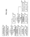
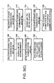
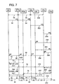
- the handover procedure of the present invention will now be described with reference to a third example in which the mobile system requests handover to a cell that is antler the control of a different DR.
- Figure 6 illustrates the network scenario of Figure 4 further adapted to illustrate this third example.
- the network elements of Figure 4 appearing in Figure 6 are referred to in Figure 6 by the same reference numerals.
- GIIs 34 and 36 are connected to different DRs.
- the GIIa 34 is connected via an internet based network interface 44 to the DRa 48.
- the GIIb 36 is connected via an internet based network interface 46 to a DR 50, labelled as DRb.
- the DRs, DRa and DRb are interconnected by a further internet based network interface 52.
- the mobile system MS 2 camped-on cell 4 has an active, ongoing packet voice connection through the BTSa (as represented by bi-directional signal 56) to GIIa (as represented by bi-directional signal 58), and DRa (as represented by bi-directional signal 200).
- the BTSa takes radio measurements of the carrier signals in the current and neighbouring cells, and an appropriate handover to the new cell 6 is determined.
- the MS maintains the connection to BTSa, and in step 102, transmits the handover request signal HR to the base transceiver station BTSa of the currently camped on cell.
- the handover request signal is forwarded to the GIIa as described before.
- step 104 it is determined that BTSb is not under the control of DRa.
- the handover request signal HR is forwarded to DRa in step 124 and in step 126 it is determined that the BTSb is not under control of DRa.
- DRa finds that BTSb is not under its control, then in a step 154 DRa checks its table of adjacent RA's if it has one, to find the DR which does control radio access for BTSb. Alternatively, DRa may signal to adjacent DR's for their routing tables of controlled RA's if it has not already done since it was last configured.
- DRa Once DRa has identified the destination DR to route the handover to, DRb, DRa prepares the path to DRb. And in step 156 forwards the handover request to DRb, as represented by signal 218 in Figure 7.
- DRb prepares a connection back to DRa and begins the network re-configuration by making the connection to the new GII, GIIb.
- a step 160 as represented by signal 220, DRb then forwards the handover request to GIIb.
- GIIb continues the re-configuration of the network by preparing to receive data for the MS TLLI, and GIIb opens the real-time connection back to DRb. GIIb then sends, in a step 164, a handover proceeding signal back to DRb, as represented by signal 224. DRb forwards the handover proceeding signal to DRa, as represented by signal 226.
- the currently camped on DR, DRa then sends back to the MS the handover proceeding signal HP via GIIa and BTSa, as indicated by signals 208, 68 and 66, to specify that the internet backbone is ready for the handover, i.e. the network has been re-configured.
- the MS Responsive to the handover proceeding signal HP, as before the MS does not release the active connection with BTSa in the current cell 4.
- the MS switches to BTSI) in the new cell 6 and sends a Packet Random Access Channel (PRACH) to start an up-link Temporary Block Flow (TBF) establishment in step 166, as indicated by signal 70 in Figure 7.
- PRACH Packet Random Access Channel
- TBF Temporary Block Flow
- the MS initiates communication with BTSb in the new cell 6.
- the up-link TBF establishment is represented by the bi-directional signals 72 in Figure 7.
- the MS waits for a confirmation from the BTSb in the new cell.
- the confirmation again comprises a packet up-link assignment in BTSb for a two-phase access, which completes the up-link TBF establishment.
- the MS switches back to BTSa and tries another handover.
- the MS If the MS is successfully allocated an up-link TBF in the new cell 6 from BTSb, in a step 168 it internally clears the connection to BTSa.
- the MS then sends a first up-link packet voice block, either containing voice or silence coding, to BTSb as represented by signal 74 in Figure 7, which in turn forwards the voice block onto the GIIb 28 as represented by signal 76.
- the voice block is then forwarded to DRb, as represented by the signal 210.
- the packet voice block is then forwarded by DRb to DRa.
- DRa receives this voice block, it forwards any subsequent voice blocks in the down-link direction to DRb.
- DRb could have a trigger on the first packet voice block received to send a message to DRa to switch connection from DRa to DRb and onto GIIb.
- the DRa then sends the next down-link voice or silence block to DRb, as represented by signal 230.
- DRb then starts down-link communication with BTSb, as represented by step 172, by forwarding this signal on to GIIb as represented by signal 232, which in turn forwards the signal onto BTSb, as represented by signal 78.
- Receipt of the signal 78 at BTSb initiates the down-link TBF establishment of BTSb with the MS.
- the TBF down-link establishment takes place in step 174 in the manner exactly as described hereinabove for the other examples, and is again represented in Figure 7 by bi-directional signals 80.
- BTSb starts down-link communication with the MS by forwarding the voice packet block to the MS as before as represented by signal 82 in Figure 7.
- a step 178 the DRA then flushes its connection with GIIa as represented by signal 214 in Figure 7, which in turn flushes its connection with BTSa as represented by signal 84 in Figure 7.
- the MS After having performed the handover procedure, the MS has an ongoing packet voice connection through BTS(b) and GII(b) to the new DR, DR(b), as represented by bi-directional signals 86, 88 and 216. As represented by signal 240, connection to the network from DRb is still provided through DRa.
- the main part of the delay introduced in the handover derives from the up-link TBF establishment and down-link TBF establishment.
- the backbone network introduces minor delays as compared to these.
- the result of the first evaluation of delay is that the up-link has a hole in transmission of about 200ms and the down-link of about 350ms.
Priority Applications (1)
| Application Number | Priority Date | Filing Date | Title |
|---|---|---|---|
| EP99306304A EP1076465A1 (de) | 1999-08-10 | 1999-08-10 | Weiterreichen für ein zellulares Netzwerk |
Applications Claiming Priority (1)
| Application Number | Priority Date | Filing Date | Title |
|---|---|---|---|
| EP99306304A EP1076465A1 (de) | 1999-08-10 | 1999-08-10 | Weiterreichen für ein zellulares Netzwerk |
Publications (1)
| Publication Number | Publication Date |
|---|---|
| EP1076465A1 true EP1076465A1 (de) | 2001-02-14 |
Family
ID=8241569
Family Applications (1)
| Application Number | Title | Priority Date | Filing Date |
|---|---|---|---|
| EP99306304A Withdrawn EP1076465A1 (de) | 1999-08-10 | 1999-08-10 | Weiterreichen für ein zellulares Netzwerk |
Country Status (1)
| Country | Link |
|---|---|
| EP (1) | EP1076465A1 (de) |
Cited By (4)
| Publication number | Priority date | Publication date | Assignee | Title |
|---|---|---|---|---|
| EP1635594A1 (de) * | 2004-09-14 | 2006-03-15 | Nokia Corporation | Verbesserter assistierter Zellwechsel |
| WO2007141575A1 (en) * | 2006-06-09 | 2007-12-13 | Siemens Aktiengesellschaft | A method of packet switched handover |
| WO2010083448A1 (en) * | 2009-01-15 | 2010-07-22 | Qualcomm Incorporated | Methods and apparatus for mobile initiated reselection in a communication network |
| US7953411B1 (en) | 2004-06-09 | 2011-05-31 | Zte (Usa) Inc. | Virtual soft hand over in OFDM and OFDMA wireless communication network |
Citations (2)
| Publication number | Priority date | Publication date | Assignee | Title |
|---|---|---|---|---|
| WO1998032303A2 (en) * | 1997-01-20 | 1998-07-23 | Nokia Telecommunications Oy | Routing area updating in packet radio network |
| EP0898438A2 (de) * | 1997-08-20 | 1999-02-24 | Nokia Mobile Phones Ltd. | Verfahren und System um einen Funkübertragungsnetzwerk zu steuern und Funkübertragungsnetzwerk steuerung |
-
1999
- 1999-08-10 EP EP99306304A patent/EP1076465A1/de not_active Withdrawn
Patent Citations (2)
| Publication number | Priority date | Publication date | Assignee | Title |
|---|---|---|---|---|
| WO1998032303A2 (en) * | 1997-01-20 | 1998-07-23 | Nokia Telecommunications Oy | Routing area updating in packet radio network |
| EP0898438A2 (de) * | 1997-08-20 | 1999-02-24 | Nokia Mobile Phones Ltd. | Verfahren und System um einen Funkübertragungsnetzwerk zu steuern und Funkübertragungsnetzwerk steuerung |
Non-Patent Citations (1)
| Title |
|---|
| "Handover Procedures (3G TS 23.009 version 3.0.0)", 3RD GENERATION PARTNERSHIP PROJECT; TECHNICAL SPECIFICATIONS GROUP CORE NETWORK, 1 May 1999 (1999-05-01), Sophia Antipolis, France, pages 14-19, XP002088537 * |
Cited By (6)
| Publication number | Priority date | Publication date | Assignee | Title |
|---|---|---|---|---|
| US7953411B1 (en) | 2004-06-09 | 2011-05-31 | Zte (Usa) Inc. | Virtual soft hand over in OFDM and OFDMA wireless communication network |
| EP1635594A1 (de) * | 2004-09-14 | 2006-03-15 | Nokia Corporation | Verbesserter assistierter Zellwechsel |
| US7519384B2 (en) | 2004-09-14 | 2009-04-14 | Nokia Corporation | Enhanced assisted cell change |
| US8081999B2 (en) | 2004-09-14 | 2011-12-20 | Nokia Corporation | Enhanced assisted cell change |
| WO2007141575A1 (en) * | 2006-06-09 | 2007-12-13 | Siemens Aktiengesellschaft | A method of packet switched handover |
| WO2010083448A1 (en) * | 2009-01-15 | 2010-07-22 | Qualcomm Incorporated | Methods and apparatus for mobile initiated reselection in a communication network |
Similar Documents
| Publication | Publication Date | Title |
|---|---|---|
| EP0872150B1 (de) | System und verfahren zur adaptiven messungssammlung und warteschlangenbildung zum weiterreichen in einem funktelekommunikationsnetzwerk | |
| US5857153A (en) | Cellular telecommunications network having seamless interoperability between exchanges while providing voice, asynchronous data and facsimile services in multiple frequency hyperbands | |
| EP1071305B1 (de) | Verfahren und Einrichtung für basisstations-kontrolliertes Weiterreichen | |
| EP1670275B1 (de) | Verfahren und Vorrichtung zur Benachrichtigung eines Funkzugangsnetzwerks eines gewählten Kernnetzes durch ein Nutzergerät in einem Netzwerk teilenden System | |
| EP1676452B1 (de) | Verfahren zum durchführen von notrufen | |
| EP1206890B1 (de) | Weiterreichen zwischen systemen | |
| KR100414410B1 (ko) | 가입자장치이용방법및셀룰러전화시스템 | |
| US5761623A (en) | Cellular telecommunications network having seamless interoperability between exchanges while supporting operation in multiple frequency hyperbands | |
| EP0549758B1 (de) | Verfahren zur durchführung einer standortsaktualisierung von einem zellularen mobilfunksystem zu einem anderen zellularen funktelefonsystem | |
| KR101454373B1 (ko) | 이동통신방법, 이동교환국, 무선기지국 및 이동국 | |
| EP0923845B1 (de) | Zwischen-vermittlung-signalisierung für dienst-änderungsanfragen während einer verbindung | |
| KR101237658B1 (ko) | 접속 확립 시스템 및 방법 | |
| EP2193669B1 (de) | Verbesserte nachbarinformationsaktualisierung in einem zellularen system | |
| EP2192749B1 (de) | Mobilkommunikationsverfahren, mobilaustauschstation, funkbasisstation und mobilstation | |
| KR20010053494A (ko) | 통신망 사이의 끊김 없는 핸드오버를 위한 방법 | |
| EP1696689A1 (de) | Weiterreichen in einem drahtlosen lokalen Breitbandnetzwerk | |
| JP2002539687A (ja) | セルの選択方法 | |
| JPH07193851A (ja) | 移動体通信システムにおける多重接続方式 | |
| EP1076465A1 (de) | Weiterreichen für ein zellulares Netzwerk | |
| US7869406B2 (en) | Method for hand-over in the mixed network asynchronous communication network and synchronous communication network | |
| JP2002519970A (ja) | セルラー無線システムのハンドオーバー方法 | |
| KR100976935B1 (ko) | 비동기망과 동기망이 혼재된 이동통신망에서의 핸드오버방법 | |
| KR101005176B1 (ko) | 비동기망과 동기망이 혼재된 이동통신망에서의 핸드오버방법 |
Legal Events
| Date | Code | Title | Description |
|---|---|---|---|
| PUAI | Public reference made under article 153(3) epc to a published international application that has entered the european phase |
Free format text: ORIGINAL CODE: 0009012 |
|
| AK | Designated contracting states |
Kind code of ref document: A1 Designated state(s): DE ES FR GB IT |
|
| AX | Request for extension of the european patent |
Free format text: AL;LT;LV;MK;RO;SI |
|
| 17P | Request for examination filed |
Effective date: 20010801 |
|
| AKX | Designation fees paid |
Free format text: DE ES FR GB IT |
|
| 17Q | First examination report despatched |
Effective date: 20031010 |
|
| STAA | Information on the status of an ep patent application or granted ep patent |
Free format text: STATUS: THE APPLICATION IS DEEMED TO BE WITHDRAWN |
|
| 18D | Application deemed to be withdrawn |
Effective date: 20050104 |