EP1076383A2 - Structure of mounting electronic unit on electric connection box - Google Patents
Structure of mounting electronic unit on electric connection box Download PDFInfo
- Publication number
- EP1076383A2 EP1076383A2 EP00306644A EP00306644A EP1076383A2 EP 1076383 A2 EP1076383 A2 EP 1076383A2 EP 00306644 A EP00306644 A EP 00306644A EP 00306644 A EP00306644 A EP 00306644A EP 1076383 A2 EP1076383 A2 EP 1076383A2
- Authority
- EP
- European Patent Office
- Prior art keywords
- electric connection
- electronic unit
- connection box
- pivot
- mounting structure
- Prior art date
- Legal status (The legal status is an assumption and is not a legal conclusion. Google has not performed a legal analysis and makes no representation as to the accuracy of the status listed.)
- Granted
Links
Images



Classifications
-
- H—ELECTRICITY
- H01—ELECTRIC ELEMENTS
- H01R—ELECTRICALLY-CONDUCTIVE CONNECTIONS; STRUCTURAL ASSOCIATIONS OF A PLURALITY OF MUTUALLY-INSULATED ELECTRICAL CONNECTING ELEMENTS; COUPLING DEVICES; CURRENT COLLECTORS
- H01R13/00—Details of coupling devices of the kinds covered by groups H01R12/70 or H01R24/00 - H01R33/00
- H01R13/62—Means for facilitating engagement or disengagement of coupling parts or for holding them in engagement
- H01R13/629—Additional means for facilitating engagement or disengagement of coupling parts, e.g. aligning or guiding means, levers, gas pressure electrical locking indicators, manufacturing tolerances
Definitions
- This invention relates to a mounting structure in which an electronic unit can be easily connected to an electric connection box, such as a junction box, so as to make an electrical connection.
- Japanese patent Publication Hei.7-135720A and Hei.9-149527A disclose a structure in which an electronic unit is moved toward an electric connection box in a parallel manner from the upper side or the lateral side, and is combined with the electronic connection box.
- Japanese Utility Publication Hei.4-137427 discloses a structure in which an electric connection box and an electronic unit are pivotally or hingedly connected together at their one ends by a pivot pin, and the electronic unit is pivotally moved to be combined with the electric connection box.
- a mounting structure including: an electronic unit including a first hinge portion and a unit body provided with one of at least one female terminal and at least one male terminal; and an electric connection box combinable with the electronic unit in a combing direction, the electric connection body including a second hinge portion and a box body provided with the other of the at least one female terminal and the at least one male terminal; wherein the at least one female terminal is electrically connected with the at least one male terminal, respectively, when the electronic unit is combined with the electric connection box, wherein the electronic unit and the electric connection box are connected together through the first hinge portion and the second hinge portion and are pivotally movable relative to each other in the combing direction, the first hinge portion and the second hinge portion can be engaged with and disengaged from each other with a one-touch operation.
- the body casings of the electric connection box and the electronic unit are pivotally connected together by the hinge mechanism releasably engaged with each other in a one-touch operation, and therefore any deflection will not occur in a positioning operation during the combining operation, and therefore all of the male terminals can be positively connected to the female terminals, respectively, thus avoiding a so-called half-fitted condition.
- one of the hinge mechanism is a pivot rod whereas the other hinge means is a partly-notched, U-shaped pivot recess in which the pivot rod is releasably engageable.
- one hinge means is the pivot rod while the other hinge means is the U-shaped pivot hole in which the pivot rod is releasably engageable, and therefore the electric connection box and the electronic unit can be easily combined together and separated from each other.
- a click engagement recess is provided at one of the two body casings whereas a click engagement projection is provided at the other body casing, and can be engaged in the click engagement recess with an attaching sound indicating the complete fitting of the male terminals in the respective female terminals.
- the click engagement projection is engaged in the click engagement recess with a feeling of click, and it can be conformed from this that all of the male terminals have been properly fitted in the female terminals, thus avoiding a half-fitted condition.
- an assist mechanism for imparting a combination-assisting force in the combining operation is provided between the two body casings.
- the assist mechanism comprising a spring or the like, is connected between the body casings of the electric connection box and the electronic unit, and a spring force assists in providing the fitting force when the electronic unit is pivotally moved upwardly to be combined with the electric connection box, and merely with this construction, the male terminals can be easily and properly connected to the female terminals, respectively.
- Fig. 1 is a side-elevational view showing a structure of mounting an electronic unit on an electric connection box, embodying the present invention.
- Fig. 2(A) is a rear view of a body casing of the electric connection box of the above embodiment.
- Fig. 2(B) is a partial cross-sectional view showing the structure of the cross section viewed along a ling A-A shown in Fig. 2 (A).
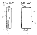
- Figs. 3(A) is a side view of the electronic unit of the above embodiment.
- Fig 3(B) is a rear view of the electronic unit of the above embodiment.
- Fig. 4 is a side-elevational view showing a structure of mounting an electronic unit on an electric connection box, forming another embodiment of the invention.
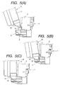
- Fig. 5(A) is a cross-sectional view showing a state before the electronic unit is mounted on the electric connection box of the present invention.
- Fig. 5(B) is a cross-sectional view showing a state in which a pivot rod of the electronic unit is fitted in a pivot recess of the electric connection box.
- Fig. 5(C) is a cross-sectional view showing a state in which the electronic unit is combined with the electric connection box.
- Fig. 1 shows the structure of this embodiment.
- the electronic unit 10 is pivotally mounted on and removable from the electric connection box 1, such as a junction box, in a removable manner.
- the electronic connection box 1 includes a body casing 2.
- a plurality of pin terminals 4, such as male terminals, for connection respectively to terminals on the electronic unit 10 are arranged on a rear surface 3 of the body casing 2, and are exposed to the exterior of the casing 2.
- the rear surface 3 serves as a mating surface with which the electronic unit 10 is mated.
- a mounting bracket 5 is provided at one end (lower end in the drawings) of the body casing 2.
- the electronic unit 10 is removably mounted on this bracket 5 and is pivotally moved to be combined with the electronic connection box.
- pivot grooves 6, such as a hole formed of an U-shape hook hole formed of partially notched, are formed in both sides of the mounting bracket 5.
- the female terminals are arranged on a body casing 11 of the electronic unit 10. These female terminals can be electrically connected respectively to the pin terminals 4 provided on the rear surface 3 of the body casing of the electric connection box 1.
- a mounting bracket 12 is provided at a lower end of the body casing 11, that is, at a position corresponding to the position of mounting of the mounting bracket 5 on the electric connection box 1.
- a pivot rods 13 formed in shaft shape are projected from both side of the mounting bracket 12. The pivot rods 13 can be respectively fitted in the pivot grooves 6 formed in the mounting bracket 5 of the electric connection box 1 with a one-touch operation.
- the two mounting brackets 5 and 12 can be releasably connected together by simply fitting the pivot rods 13 in the pivot grooves 6 (that is, by fitting the convex and concave portions together), and with this construction the electric connection box 1 and the electronic unit 10 can be easily combined and released with each other.
- a click engagement recess 7 is provided at the rear surface 3 of the body casing 2 of the electric connection box 1.
- a click engagement projection (convex portion) 14 is formed on the body casing 11 of the electronic unit 10 and can be engaged in the click engagement recess 7 in a one-touch manner with an attaching sound. Therefore, a feeling of attachment can be confirmed when the male terminals are completely fitted respectively in the female terminals in the combining operation.
- the electronic unit 10 is combined with the electric connection box 1, so that the female terminals are electrically connected to the male terminals, respectively.
- the pivot rods 13, provided on the mounting bracket 12 on the electronic unit 10 are respectively engaged in the pivot grooves 6 in the mounting bracket 5 on the electric connection box 1 with a one-touch operation, thereby hingedly connecting the two mounting brackets 5 and 12 together.
- the electronic unit 10 is pivotally moved upwardly about the hinge connection portion including the pivot rods 13, as indicated by an arrow in Fig. 1, and is connected to the body casing 2 of the electric connection box 1 to be combined therewith.
- the female terminals on the electronic unit 10 are electrically connected respectively to the pin terminals 4 on the electric connection box 1.
- the body casings 2 and 11 of the electric connection box 1 and the electronic unit 10 do not particularly need to be positioned relative to each other. It is only necessary to pivotally move the electronic unit 10 upwardly about the pivot rods 13. At this time, the click engagement projection 14 is engaged in the click engagement recess 7 with an attaching sound. Therefore, the connection of the female terminals to the male terminals can be confirmed through this sound. Even in the case where the number of the male and female terminals (such as the pin terminals 4 on the electric connection box 1) is large, the male and female terminals can be properly connected together with a small fitting force since the pivot rods 13 on the body casing 11 of the electronic unit 10 serve as a supporting point of leverage. Therefore a half-fitted condition (electrically incompletely-connected condition) is avoided.
- the electric connection box 1 and the electronic unit 10 in an assembled condition can be easily disconnected or separated from each other in the sequence reverse to that of the above combining operation.
- the electric connection box 1 and the electronic unit 10 are not always kept in integrally-connected relation to each other, but the two can be disconnected from each other when necessary. Therefore the bulky assembly can be avoided, and this is advantageous from the viewpoints of stock and transport.
- a fitting force for connecting male and female terminals together is become large relative to an increase in a number of male and female terminals.
- the above embodiment can provide the structure with operating with a sufficient small fitting force.
- Fig. 4 shows another embodiment of the invention in which there is provided means for assisting in providing the fitting force.
- an assist mechanism 20 for producing a force to assist in imparting the fitting force is mounted between the body casings 2 and 11 connected together through the hinge connection portions defined respectively by the pivot grooves 6 and the pivot rods 13.
- the two body casings 2 and 11 are pivotally connected together by connection levers 21 and 22 through lever pins 21a and 22a, and a spring member 23 is connected between the lever pins 21a and 22a.
- the body casings of the electric connection box and the electronic unit are pivotally connected together by the hinge means releasably engaged with each other in a one-touch manner. Therefore any deflection will not occur in the positioning operation during the combining operation, and therefore all of the male terminals can be positively connected to the female terminals, respectively, thus effectively avoiding a so-called half-fitted condition.
- one hinge means is the pivot rod while the other hinge means is the U-shaped pivot hole in which the pivot rod is releasably engageable. Therefore the electric connection box and the electronic unit can be easily combined together and separated from each other, thus providing enhanced usability.
- the click engagement projection is engaged in the click engagement recess with a feeling of click. It can be conformed from this that all of the male terminals have been properly fitted in the female terminals. Thus effectively avoiding a half-fitted condition.
- the assist mechanism having a spring or the like is connected between the body casings of the electric connection box and the electronic unit.
- a spring force assists in providing the fitting force when the electronic unit is pivotally moved upwardly to be combined with the electric connection box.
- the male terminals can be easily and properly connected to the female terminals, respectively.
Landscapes
- Details Of Connecting Devices For Male And Female Coupling (AREA)
- Connection Or Junction Boxes (AREA)
Abstract
Description
Wire harnesses, cables and wire harness have been increasingly used. Recently, in order to avoid the complicatedness, there have been extensively used structures in which an electronic unit is mechanically connected to an electronic connection box incorporating as many wire harnesses as possible, and the electronic unit and an electronic connection box are electrically such that male terminals and female terminals, provided in the electric connection box and the electronic unit respectively, are electrically connected together.
Claims (12)
- A mounting structure comprising:wherein said at least one female terminal is electrically connected with said at least one male terminal, respectively, when said electronic unit is combined with said electric connection box,an electronic unit including a first hinge portion and a unit body provided with one of at least one female terminal and at least one male terminal; andan electric connection box combinable with said electronic unit in a combing direction, said electric connection body including a second hinge portion and a box body provided with the other of said at least one female terminal and said at least one male terminal;
wherein said electronic unit and said electric connection box are connected together through said first hinge portion and said second hinge portion and are pivotally movable relative to each other in said combing direction, said first hinge portion and said second hinge portion can be engaged with and disengaged from each other with a one-touch operation. - A mounting structure according to claim 1, wherein said first hinge portion is a pivot rod, said second hinge portion is a U-shaped pivot recess formed by partially notched said body hinge portion, said pivot rod and said pivot recess are releasably engageable with each other.
- A mounting structure according to claim 1, wherein said first hinge portion is a U-shaped pivot recess formed by partially notched said first hinge portion, said second hinge portion is a pivot rod, said pivot rod and said pivot hole are releasably engageable with each other.
- A mounting structure according to claim 1, wherein a click engagement recess is provided at one of said unit body and said box body, a click projection engageable with said engagement recess is provided at the other of said unit body and said box body.
- A mounting structure according to claim 4, wherein said click projection is engaged with said engagement recess with an attaching sound indicating the complete fitting of said at least one male terminal in said respective at least one female terminal.
- A mounting structure according to claim 1, wherein an assist mechanism for imparting a combination-assisting force in a combination operation is provided between said unit body and said box body.
- A mounting structure comprising:wherein said at least one female terminal is electrically connected with said at least one male terminal, respectively, when said electronic unit is combined with said electric connection box,an electronic unit including a unit body provided with one of at least one female terminals and at least one male terminal; andan electric connection box combinable with said electronic unit in a combing direction, said electric connection body including a box body provided with the other of said at least one female terminal and said at least one male terminal;
wherein said electronic unit and said electric connection box are provided with a hinge mechanism, said hinge mechanism connect said electronic unit and said electric connection box and enable said electronic unit and said electric connection box to be pivotally movable relative to each other in said combing direction, said hinge mechanism can engage with and disengage from said electronic unit and said electric connection box with one-touch operation. - A mounting structure according to claim 7, wherein said hinge mechanism of said electronic unit is a pivot rod, said hinge mechanism of said electric connection box is a U-shaped pivot recess formed by partially notched said electric connection box, said pivot rod and said pivot recess are releasably engageable with each other.
- A mounting structure according to claim 7, wherein said hinge mechanism of said electronic unit is a U-shaped pivot recess formed by partially notched said electronic unit, said hinge mechanism of said electric connection is a pivot rod, said pivot rod and said pivot recess are releasably engageable with each other.
- A mounting structure according to claim 7, wherein a click engagement recess is provided at one of said unit body and said box body, a click projection engageable with said engagement recess is provided at the other of said unit body and said box body.
- A mounting structure according to claim 10, wherein said click projection is engaged with said engagement recess with an attaching sound indicating the complete fitting of said at least one male terminal in said respective at least one female terminal.
- A mounting structure according to claim 7, wherein an assist mechanism for imparting a combination-assisting force in a combination operation is provided between said unit body and said box body.
Applications Claiming Priority (2)
| Application Number | Priority Date | Filing Date | Title |
|---|---|---|---|
| JP22650499 | 1999-08-10 | ||
| JP11226504A JP2001057723A (en) | 1999-08-10 | 1999-08-10 | Electronic unit mounting structure to electrical junction box |
Publications (3)
| Publication Number | Publication Date |
|---|---|
| EP1076383A2 true EP1076383A2 (en) | 2001-02-14 |
| EP1076383A3 EP1076383A3 (en) | 2002-04-03 |
| EP1076383B1 EP1076383B1 (en) | 2006-04-26 |
Family
ID=16846164
Family Applications (1)
| Application Number | Title | Priority Date | Filing Date |
|---|---|---|---|
| EP00306644A Expired - Lifetime EP1076383B1 (en) | 1999-08-10 | 2000-08-04 | Structure of mounting electronic unit on electric connection box |
Country Status (5)
| Country | Link |
|---|---|
| US (1) | US6648678B1 (en) |
| EP (1) | EP1076383B1 (en) |
| JP (1) | JP2001057723A (en) |
| AU (1) | AU764715B2 (en) |
| DE (1) | DE60027513T2 (en) |
Families Citing this family (11)
| Publication number | Priority date | Publication date | Assignee | Title |
|---|---|---|---|---|
| US7367121B1 (en) | 2000-01-05 | 2008-05-06 | Protectconnect | Electrical wiring method |
| US6884111B2 (en) | 2002-05-23 | 2005-04-26 | Protectconnect | Safety module electrical distribution system |
| US7316376B1 (en) | 2003-08-21 | 2008-01-08 | Engler John C | Apparatus for pivotably mounting an electrical enclosure |
| US7312396B1 (en) | 2004-03-13 | 2007-12-25 | Protectconnect, Inc. | Universal electrical wiring component |
| US20080053698A1 (en) * | 2006-07-29 | 2008-03-06 | Steve Purves | Pre-wired power distribution system |
| JP4990635B2 (en) * | 2007-01-10 | 2012-08-01 | 矢崎総業株式会社 | Electrical junction box |
| JP5101891B2 (en) * | 2007-01-10 | 2012-12-19 | 矢崎総業株式会社 | Electrical junction box |
| JP5088811B2 (en) * | 2007-01-10 | 2012-12-05 | 矢崎総業株式会社 | Electrical junction box |
| JP5088812B2 (en) * | 2007-01-10 | 2012-12-05 | 矢崎総業株式会社 | Electrical junction box |
| US7393220B1 (en) | 2007-04-18 | 2008-07-01 | Yazaki North America, Inc. | Electrical connector assembly connected upon rotation about a bracket |
| CN114044175B (en) * | 2021-10-30 | 2023-05-26 | 西南电子技术研究所(中国电子科技集团公司第十研究所) | On-orbit dragging-off tool for chassis in manned space capsule |
Family Cites Families (14)
| Publication number | Priority date | Publication date | Assignee | Title |
|---|---|---|---|---|
| JPS61121150U (en) * | 1985-01-18 | 1986-07-30 | ||
| US4972296A (en) * | 1989-06-15 | 1990-11-20 | Northern Telecom Limited | Expandable modular switching unit |
| JP2563310Y2 (en) * | 1990-06-05 | 1998-02-18 | 矢崎総業株式会社 | Box hinge structure |
| JP2976137B2 (en) | 1990-09-28 | 1999-11-10 | キヤノン株式会社 | Electron beam generator, image forming apparatus and recording apparatus using the same |
| US5639253A (en) * | 1993-03-29 | 1997-06-17 | Oy Euro Equipment Ltd. | Extension plug-in unit |
| US5308261A (en) * | 1993-07-13 | 1994-05-03 | General Motors Corporation | Low profile connector position assurance |
| JP2900215B2 (en) | 1993-11-10 | 1999-06-02 | 矢崎総業株式会社 | Electronic unit guide structure |
| US5941846A (en) * | 1995-03-13 | 1999-08-24 | Alaris Medical Systems, Inc. | Method and apparatus for power connection in a modular patient care system |
| JP3081780B2 (en) | 1995-11-21 | 2000-08-28 | 矢崎総業株式会社 | Electrical junction box |
| JP3046759B2 (en) * | 1995-11-30 | 2000-05-29 | 矢崎総業株式会社 | Electrical junction box |
| JP3143397B2 (en) * | 1996-07-26 | 2001-03-07 | 矢崎総業株式会社 | Connection structure between electronic unit and electrical junction box |
| JP3435009B2 (en) * | 1997-03-14 | 2003-08-11 | 矢崎総業株式会社 | Electrical junction box |
| US6133531A (en) * | 1998-11-03 | 2000-10-17 | Pass & Seymour, Inc. | Weatherproof outlet cover |
| CN107002011B (en) * | 2014-12-08 | 2024-03-19 | 美国圣戈班性能塑料公司 | Closed system for extraction of separation media |
-
1999
- 1999-08-10 JP JP11226504A patent/JP2001057723A/en active Pending
-
2000
- 2000-08-04 EP EP00306644A patent/EP1076383B1/en not_active Expired - Lifetime
- 2000-08-04 DE DE60027513T patent/DE60027513T2/en not_active Expired - Lifetime
- 2000-08-07 AU AU51844/00A patent/AU764715B2/en not_active Ceased
- 2000-08-10 US US09/635,406 patent/US6648678B1/en not_active Expired - Lifetime
Also Published As
| Publication number | Publication date |
|---|---|
| US6648678B1 (en) | 2003-11-18 |
| AU764715B2 (en) | 2003-08-28 |
| EP1076383A3 (en) | 2002-04-03 |
| EP1076383B1 (en) | 2006-04-26 |
| AU5184400A (en) | 2001-02-15 |
| JP2001057723A (en) | 2001-02-27 |
| DE60027513T2 (en) | 2006-09-07 |
| DE60027513D1 (en) | 2006-06-01 |
Similar Documents
| Publication | Publication Date | Title |
|---|---|---|
| JP3204397B2 (en) | Micro pin connector mechanism | |
| JP3074644U (en) | Electrical connector with improved latching mechanism | |
| EP1318570A1 (en) | A connector and method of assembling it | |
| JPH07220807A (en) | Connector housing with lock | |
| US6648678B1 (en) | Structure of rotatably mounting an electronic unit on an electrical connection box in a removable manner | |
| JP2002524834A (en) | Socket contact elements for electrical connectors | |
| US5112239A (en) | Electrical connector | |
| KR20180101631A (en) | Terminal fitting | |
| KR20180044437A (en) | Terminal fitting | |
| JP3945306B2 (en) | Electrical junction box | |
| JPH08315926A (en) | Low insertion force connector | |
| JP3263899B2 (en) | Electrical connector with terminal position assurance mechanism | |
| US20070190833A1 (en) | Lever fitting-type connector | |
| EP1403979B1 (en) | A connector assembling construction and assembling method | |
| US7661969B2 (en) | Lever fitting connector | |
| US5564953A (en) | Divided-type multi-pole connector | |
| JP7483838B2 (en) | Connector Assembly | |
| JP7406233B2 (en) | electrical connection device | |
| EP1601063B1 (en) | A connector device | |
| JPH09120864A (en) | Connector with locking mechanism | |
| EP1530265A2 (en) | A connector housing assembly and an electric connector assembly | |
| US6203352B1 (en) | Connector having a shielding member | |
| JP3997871B2 (en) | connector | |
| JP4066965B2 (en) | connector | |
| JP2940894B2 (en) | Lever connector |
Legal Events
| Date | Code | Title | Description |
|---|---|---|---|
| PUAI | Public reference made under article 153(3) epc to a published international application that has entered the european phase |
Free format text: ORIGINAL CODE: 0009012 |
|
| AK | Designated contracting states |
Kind code of ref document: A2 Designated state(s): DE FR GB Kind code of ref document: A2 Designated state(s): AT BE CH CY DE DK ES FI FR GB GR IE IT LI LU MC NL PT SE |
|
| AX | Request for extension of the european patent |
Free format text: AL;LT;LV;MK;RO;SI |
|
| PUAL | Search report despatched |
Free format text: ORIGINAL CODE: 0009013 |
|
| AK | Designated contracting states |
Kind code of ref document: A3 Designated state(s): AT BE CH CY DE DK ES FI FR GB GR IE IT LI LU MC NL PT SE |
|
| AX | Request for extension of the european patent |
Free format text: AL;LT;LV;MK;RO;SI |
|
| 17P | Request for examination filed |
Effective date: 20020912 |
|
| AKX | Designation fees paid |
Free format text: DE FR GB |
|
| 17Q | First examination report despatched |
Effective date: 20050613 |
|
| GRAP | Despatch of communication of intention to grant a patent |
Free format text: ORIGINAL CODE: EPIDOSNIGR1 |
|
| GRAS | Grant fee paid |
Free format text: ORIGINAL CODE: EPIDOSNIGR3 |
|
| GRAA | (expected) grant |
Free format text: ORIGINAL CODE: 0009210 |
|
| AK | Designated contracting states |
Kind code of ref document: B1 Designated state(s): DE FR GB |
|
| REG | Reference to a national code |
Ref country code: GB Ref legal event code: FG4D |
|
| REF | Corresponds to: |
Ref document number: 60027513 Country of ref document: DE Date of ref document: 20060601 Kind code of ref document: P |
|
| ET | Fr: translation filed | ||
| PLBE | No opposition filed within time limit |
Free format text: ORIGINAL CODE: 0009261 |
|
| STAA | Information on the status of an ep patent application or granted ep patent |
Free format text: STATUS: NO OPPOSITION FILED WITHIN TIME LIMIT |
|
| 26N | No opposition filed |
Effective date: 20070129 |
|
| REG | Reference to a national code |
Ref country code: FR Ref legal event code: PLFP Year of fee payment: 17 |
|
| REG | Reference to a national code |
Ref country code: FR Ref legal event code: PLFP Year of fee payment: 18 |
|
| REG | Reference to a national code |
Ref country code: FR Ref legal event code: PLFP Year of fee payment: 19 |
|
| PGFP | Annual fee paid to national office [announced via postgrant information from national office to epo] |
Ref country code: DE Payment date: 20180724 Year of fee payment: 19 Ref country code: FR Payment date: 20180712 Year of fee payment: 19 |
|
| PGFP | Annual fee paid to national office [announced via postgrant information from national office to epo] |
Ref country code: GB Payment date: 20180801 Year of fee payment: 19 |
|
| REG | Reference to a national code |
Ref country code: DE Ref legal event code: R119 Ref document number: 60027513 Country of ref document: DE |
|
| GBPC | Gb: european patent ceased through non-payment of renewal fee |
Effective date: 20190804 |
|
| PG25 | Lapsed in a contracting state [announced via postgrant information from national office to epo] |
Ref country code: DE Free format text: LAPSE BECAUSE OF NON-PAYMENT OF DUE FEES Effective date: 20200303 Ref country code: FR Free format text: LAPSE BECAUSE OF NON-PAYMENT OF DUE FEES Effective date: 20190831 |
|
| PG25 | Lapsed in a contracting state [announced via postgrant information from national office to epo] |
Ref country code: GB Free format text: LAPSE BECAUSE OF NON-PAYMENT OF DUE FEES Effective date: 20190804 |