BACKGROUND OF THE INVENTION
This invention relates to an elastic wave generator, magnetostriction
oscillator mounting structure and method.
The elastic wave generator may be said as a devise for generating an
acoustic longitudinal elastic wave and expected to be utilized in the following
variety of fields:
Heretofore, the method for applying a stress to a mechanical structure
includes a hydraulic press generating a static compression stress, an expansion
test machine generating a static tensile force or a hammer or a falling object
generating a dynamic stress. In the method using the hammer or the falling
object, it is difficult to control the stress at will so that the detailed examination of
the workpiece cannot be carried out.
On the other hand, a method for converting the strain into stress as a
method for freely controlling the stress is used in acoustic measurement of a
relatively small structure having a relatively small thickness or even composition.
However, since this method is not suitable for use in terms of a large structure or
a sparse material which needs a large stress, the measurement of these
materials had to be achieved by generating a large stress by a hammer or a
falling substance.
Therefore, in order to generate a controlled large stress, an attention has
been paid to materials that have extremely high strain characteristics and a
strain-stress conversion apparatus utilizing these materials (piezoelectric material,
supermagnetostriction material) has been studied. However, these materials,
such as brittle and weak sintered alloys or easily bendable and deformable
materials, have compression strengths that are too small not to self-destroy upon
the generation of the strain in the stressed state.
While it has been known that the generated stress can be made large
when the strain is generated by energizing the piezoelectric material or the
magnetostriction material put under the pre-stressed state, the compression
strength of the material was too small and the material was self-destroyed when
a strain is generated even with a small pre-stress. Therefore, it was not possible
to obtain at will a large stress, such as a stress of 10 - 30 kgf/mm2, in order to
generate a strong elastic wave (acoustic signal), so that this material was not
suitable to apply to a large structural body or a sparse material.
Therefore, while strain-stress conversion device employing these
materials (piezoelectric material, super magnetostriction material) having high
strain characteristics have been used in the acoustic measurement of a relatively
thin matter or a structural body of a homogeneous composition, the measurement
with the hammer of the falling object has conventionally been used for a large
structural body or the materials of sparse composition. Although the realization
of the acoustic transmission through the use of the drill pipes for oil rigs of a
length of from several hundred meters to several thousand meters have been
believed, since there has been provided no realistic acoustic longitudinal elastic
wave generator that can provide a large stress wave, the pressure wave
transmission or mud pulse system in which dug muddy water is used as the
transmission medium.
According to the study and the analysis of the inventors of the present
invention, the unsolved technical problems in these conventional fields of
application are given below:
Then, the present invention is expected to be utilized in a wide variety of
fields as discussed previously, so that both the present invention and the
conventional technique will be described in terms of examples in which they are
applied to the field of drilling rigs.
For example, Japanese Patent Laid-Open No. 8-130511 discloses the
system in which the information of the bottom of the well being dug in an oil well
is transmitted by an elastic wave (acoustic) signal using the drill pipes as a
transmission medium.
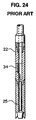
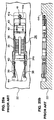
Figs. 23 to 25b are views showing the system disclosed in Japanese
Patent Laid-Open No. 8-130511 and Fig. 23 being a view showing the overall
construction of the oil well facility, Fig. 24 being a fragmental sectional view
showing the drill collar portion at the well bottom of the drill pipe, Fig. 25a being a
plan view and Fig. 25b being a sectional side view.
In Figures 23 - 25b, 100 shows a tower for digging an oil well. 24 is a
drill pipe inserted into the ground from the tower 100 and having straight
cylindrical pipes each having a length of about 8 meters connected to constitute
an assembly of a length of several hundred meters to several thousand meters,
the drill pipe being driven to rotate by an unillustrated drive unit mounted to the
well tower 100. Disposed within the drill collar 22 of the drill pipe 24 at the
bottom portion of the well is a magnetostriction oscillator 34. 25 is a sensor for
detecting various information necessary for drilling, the various information
signals from the sensor 25 at the well bottom are converted into digital signals so
that an electric current varying in accordance with the converted digital
information signal is supplied to an excitation coil 36 of the magnetostriction
oscillator 34, which converts the signal into an elastic wave (acoustic signal) to be
transmitted through the drill pipe 24 to the ground surface. 26 is a receiver
installed in the portion of the tower 100 of the drill pipe 24, 27 is a signal
processing apparatus for processing to demodulate the received signal of the
receiver 26 to monitor the state of the bottom of the well such as the temperature
of the well, the tilt of the drill bit or the like.
The mounting of the magnetostriction oscillator 34 to the drill collar 22 is
achieved by the cantilevered mounting as shown in the sectional side view of
Figs. 25a and 25b in which a clamping screws 39 and rock nuts 40 are used to
be canti-lever attachment (canti-levered system), so that when the
magnetostriction oscillator 34 is elongated by energization, the reaction force
from the inertia weight 42 disposed at the free end side is transmitted to the drill
collar 22 through the horn 38 to become an elastic wave. Therefore, the
injection efficiency of the elastic wave (acoustic) energy from the magnetostriction
oscillator 34 to the drill pipe 24 is in the order of 0.01 to 0.1, so that, when the
drill pipe 24 of several hundred meters to several thousand meters long is used
as a transmission medium in actuality, the elastic wave (acoustic wave) does not
reach the receiver 26 at the ground level and this system is not practically used in
the oil well digging but the pressure wave transmission or mud pulse system in
which digging mud water is used as a transmission medium is utilized.
Thus, according to the elastic wave generating device employing the
conventional magnetostriction oscillator 34, it is difficult to generate and inject a
large stress wave (elastic wave) of a desired size in a large structural body.
DISCLOSURE OF THE INVENTION
The present invention has been made in order to solve the above-discussed
problems and has as its object the provision of an elastic wave
generator, a magnetostriction oscillator mounting structure and a mounting
method free from the above-discussed problems.
With the above objects in view, the present invention resides in an elastic
wave generator comprising: an excitation coil; a magnetostriction oscillator
around which the excitation coil is wound and made of a lamination of
magnetostriction sheets having a metallic crystalline structure which exhibits
positive strain characteristics in which its length varies directionally upon
magnetic excitation; and an oscillator support having a first support surface
shrink-fit against a first end surface of the magnetostriction oscillator intersecting
the direction along which the length of the magnetostriction oscillator changes
and a second support surface shrink-fit against a second end surface of the
magnetostriction oscillator intersecting the direction along which the length of the
magnetostriction oscillator changes, whereby the changes in the length of the
magnetostriction oscillator due to the magnetic excitation of the excitation coil
appearing at the first and second end surfaces is directly supported by the first
and second support surfaces. Therefore, the elastic wave generator can be
realized in which the generation and the injection of a large stress wave (elastic
wave) that has not heretofore been solved.
The elastic wave generator may comprise an excitation coil; a
magnetostriction oscillator around which the excitation coil is wound and made of
a lamination of magnetostriction sheets having a metallic crystalline structure
which exhibits positive strain characteristics in which its length varies directionally
upon magnetic excitation; a magnetic bias device having a magnetic path in
common with the magnetostriction oscillator, and an oscillator support having a
first support surface shrink-fit against a first end surface of the magnetostriction
oscillator intersecting the direction along which the length of the magnetostriction
oscillator changes and a second support surface shrink-fit against a second end
surface of the magnetostriction oscillator intersecting the direction along which
the length of the magnetostriction oscillator changes, whereby the changes in the
length of the magnetostriction oscillator due to the magnetic excitation of the
excitation coil appearing at the first and second end surfaces is directly supported
by the first and second support surfaces. Therefore, the elastic wave generator
can be realized in which the generation and the injection of a large stress wave
(elastic wave) that has not heretofore been solved and the operating point can be
arbitrarily set.
The present invention also resides in an elastic wave generator mounting
structure for mounting a magnetostriction oscillator to an object to which an
elastic wave is irradiated, the magnetostriction oscillator comprising an excitation
coil wound around a stack of thin sheets of a metallic magnetostriction material
bonded together with an electrically insulating bonding agent for generating an
elastic wave in the direction parallel to the thin sheet by an excitation current
flowing through the excitation coil; the magnetostriction oscillator having two
parallel surfaces intersecting at right angles with an elastic wave radiation
direction and spaced apart from each other by a distance A at room temperature
and a distance A1 at a lower temperature; the object having a hole or a recess
having two parallel wall surfaces intersecting at right angles with the elastic wave
radiation direction and spaced apart from each other by a distance B at room
temperature; a relationship among the distances being A > B > A1; and the
magnetostriction oscillator being held in the hole or recess by the shrink-fit
against the wall surfaces in which the magnetostriction oscillator is cooled and
contracted and then returning to room temperature to expand the
magnetostriction oscillator within the hole or recess. Therefore, the
magnetostriction oscillator is held in the pre-stressed state by the shrink-fit, so
that the pre-stress incomparably stronger than that obtained by the conventional
tightening screw can be applied.
The present invention also resides in a method for mounting a
magnetostriction oscillator to an object to which an elastic wave is irradiated, the
magnetostriction oscillator comprising an excitation coil wound around a stack of
thin sheets of a metallic magnetostriction material bonded together with an
electrically insulating bonding agent for generating an elastic wave in the direction
parallel to the thin sheet by an excitation current flowing through the excitation
coil; the method comprising: a magnetostriction oscillator shaping step for
shaping two opposing elastic wave radiation surfaces formed by stacking the thin
sheets into two parallel surfaces intersecting at right angles with an elastic wave
radiation direction and spaced apart from each other by a distance A at room
temperature; an object shaping step for providing a hole or a recess having two
parallel wall surfaces intersecting at right angles with the elastic wave radiation
direction and spaced apart from each other by a distance B at room temperature
between two wall surfaces at room temperature which is smaller than the
distance A; a cooling step for cooling the magnetostriction oscillator until the
distance A becomes equal to a distance A1 smaller than the distance B of the
hole or the recess; and an insertion step for inserting the cooled magnetostriction
oscillator into the hole or recess. Therefore, the magnetostriction oscillator is
held between the wall surfaces of the recess or the hole in the shrink-fit state due
to the expansion at the room temperature before the cooling, so that it is held in
the pre-stressed state due to the shrink-fit that is incomparably stronger than that
obtained by the conventional tightening screw can be applied.
BRIEF DESCRIPTION OF THE DRAWINGS
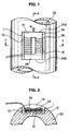
Fig. 1 is a plan view of an elastic wave generator of the first embodiment
of the present invention;
Fig. 2 is a sectional view taken along line A - A of Fig. 1;
Fig. 3 is a circuit diagram of the first embodiment of the present invention:
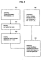
Fig. 4 is a flow chart showing the magnetostriction oscillator mounting
method according to the first embodiment of the present invention;
Figs. 5a and 5b are views for explaining the step S1 in the flow chart of
Fig. 4;
Fig. 6 is a view for explaining the abrading step of step S11 in the flow
chart of Fig. 4;
Fig. 7 is a view for explaining the winding step of step S21 in the flow
chart of Fig. 4;
Figs. 8a to 8c are views for explaining the machining step of step S41 in
the flow chart of Fig. 4;
Fig. 9 is a view for explaining the cooling step of step S31 in the flow
chart of Fig. 4;
Fig. 10 is a view for explaining the inserting step of step S51 in the flow
chart of Fig. 4;
Fig. 11 is a view for explaining the value of the pre-loading based on the
difference between the recess dimension and the core dimension;
Fig. 12 is a view for explaining the variation in saturation magnetostriction
strain rate due to the difference in the pre-loading;
Figs. 13a and 13b are sectional views for the hole for mounting the
magnetostriction oscillator according to the second embodiment of the present
invention;
Fig. 14 is a view for explaining the core stacking operation in the
magnetostriction oscillator mounting method according to the third embodiment of
the present invention;
Fig. 15 is a view for explaining the manner of mounting of Fig. 14;
Fig. 16 is a perspective view showing the elastic wave generator
according to the fourth embodiment of the present invention;
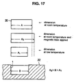
Fig. 17 is a view for explaining the dimensions used in the mounting
method of the fifth embodiment of the present invention;
Fig. 18 is a view for explaining the assembled state of the core in the
mounting method according t the fifth embodiment of the present invention;
Fig. 19 is a flow chart showing the operation of Fig. 18;
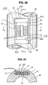
Fig. 20 is a plan view of an elastic wave generator of the sixth
embodiment of the present invention;
Fig. 21 is a sectional view taken along line A - A of Fig. 20;
Fig. 22 is a graph showing the characteristics of the magnetostriction
characteristics of the magnetostriction oscillator assembled by the pre-loading;
Fig. 23 is a view for explaining a conventional oil dig facility;
Fig. 24 is a detailed sectional view of the well bottom portion of the drill
pipe shown in Fig. 23; and
Figs. 25a and 25b are plan views showing the manner of mounting the
magnetostriction oscillator shown in Fig. 24.
DESCRIPTION OF THE PREFERRED EMBODIMENTS
Embodiment 1
The elastic wave generator of the present invention will now be described
in terms of the oil well facility, in which the oscillator support (object) is drill collar
(tubular body) used in the oil digging facility. Fig. 1 is a plan view showing the
state in which the magnetostriction oscillator is mounted, Fig. 2 is a sectional view
taken along line Y - Y of Fig. 1 and Fig. 3 is a circuit diagram elastic wave
generator.
In Figs. 1 - 3, 22 is a non-magnetic magnetostriction oscillator support to
which the object is to be mounted, which is the drill collar (tubular body) made of
stainless steel in the oil digging facility, and a recess 1 having a rectangular
shape in plan is formed in the front surface. 1A and 1B are precisely flat support
surfaces parallel to each other and are polished into a mirror finish. 1C is a flat
bottom surface of the recess 1 that is at right angles to the support surfaces 1A
and 1B. 1D and 1E are sidewall surfaces defining right angles with respect to
the support surfaces 1A and 1B and are parallel to each other.
34 is a magnetostriction oscillator having positive strain characteristics in
which its length directionally expands upon the excitation, the magnetostriction
thin sheets of a metallic crystalline structure such as an iron-chromium alloy, an
iron-cobalt alloy or the like are stacked into a lamination with an electric insulation
between each of the magnetostriction thin sheets and secured into a rigid body
by a thermo-setting resin.
A practically suitable magnetostriction thin sheet having a positive strain
characteristic includes a Fe-Co magnetostriction alloy (such as C: 008 wt%, Si:
0.08 wt%, Mn: 0.07 wt%, Co: 49.22 wt%, Vt: 1.546 wt% and Fe: residuary)
disclosed in Japanese Patent Laid-Open No. 10-88301 entitled "iron-cobalt alloy
plate manufacturing method". While an alloy of Fe-70 wt% Co is known as as
an iron-cobalt alloy and an alloy of Fe-Al is known as an alloy of low magnetic
permeability, these alloys are not suitable to be used for the purpose of the
present invention.
The magnetostriction oscillator 34 is firmly connected to the oscillator
support 22 within the recess 1, with one end surface 34A of the magnetostriction
oscillator 34 made shrink-fit against one of the support surface 1A of the recess 1
and the other end surface 34B made shrink-fit against the other end surface 34B.
Also, the respective end surfaces 34A and 34B of the magnetostriction oscillator
34 are polished into a flat mirror surface in a manner similar to the support
surfaces 1A and 1B of the oscillator support 22. The term "shrink-fit" herein
means cooling-fit and heating-fit. The pre-load (pressurization) applied to the
magnetostriction oscillator 34 by the shrink-fit at this time is 10 - 30 kg/mm2 and,
to obtain a pre-load of 30 kg/mm2, the material of the magnetostriction oscillator
34 needs to have a compression strength of about 125 kg/mm2.
36 is a magnetic excitation coil wound around the magnetostriction
oscillator 34 and is installed completely within the recess 1 without projecting
therefrom together with the magnetostriction oscillator 34. The excitation coil 36
is supplied with an output current representative of the well-bottom information
from the current supply apparatus 36S, which generates a current corresponding
to the digital signal modulated by the modulator 25M in accordance with the
output from the sensor 25 detecting the well-bottom information, such as the
temperature of the bottom of the oil well, the inclination or the azimuth of the drill
blades at the bottom end of the drill pipe 22.
When an output current corresponding to the well-bottom information is
supplied to the excitation coil 36, the excitation coil 36 generates a magnetic field
corresponding to the well-bottom information, causing the magnetostriction
oscillator 34 having positive strain characteristics to elongate in the direction of an
arrow W in Fig. 1 by the generated magnetic field corresponding to the well-bottom
information due to the alignment of the magnetic domain. As a result,
the large inner stresses (pre-stresses) in the magnetic restriction oscillator 34 and
the oscillator support 22 given by the shrink-fit are further increased to become a
large stress wave (elastic wave), which is transmitted at a high speed through the
drill collar and the drill pipes connected together to the receiver (the receiver 26 in
Fig. 21) on the ground surface so that the circumstances at the well-bottom may
be monitored according to the output from the demodulator 27 (Fig. 21) on the
ground surface.
As seen also from Fig. 1, the opposite end surfaces 34A of the
magnetostriction oscillator 34 and the opposing support surfaces 1A of the
oscillator support 22 are directed to intersect (intersect at right angles in Fig. 1)
with the direction of expansion (the direction of the arrow W) due to the excitation
of the magnetostriction oscillator 34 by the excitation coil 36.
According to the utility experiments conducted by the inventors of the
present invention, the magnetostriction oscillator 3 is constructed such that the
excitation coil 36 is wound around it and is made of the stack of magnetostriction
sheets having a metallic crystalline structure which exhibits positive strain
characteristics in which its length varies directionally upon magnetic excitation,
and the non-magnetic oscillator support 22 having the first support surface 1A
shrink-fit against the first end surface 34A of the magnetostriction oscillator 34
intersecting the direction along which the length of the magnetostriction oscillator
34 changes and the second support surface 1B shrink-fit against the second end
surface 34B of the magnetostriction oscillator 34 intersecting the direction along
which the length of the magnetostriction oscillator 34 changes are provided and
the changes in the length of the magnetostriction oscillator 34 due to the
magnetic excitation of the excitation coil 36 appearing at the first and second end
surfaces 1A and 1B are directly supported by the first and second support
surfaces 1A and 1B, so that a large stress such as a stress of 10 - 30 kgf/mm2
which has not heretofore been expected to be obtainable according to the
conventional technique can be realized at will.
Also, the injection efficiency of the elastic wave (stress wave, acoustic
wave) energy from the magnetostriction oscillator 34 into the oscillator support 22
(the drill collar, tubular body, object) is substantially equal to 1 which is
significantly reduced from 0.01 to 0.1 of that of the conventional design.
Also, although, in the oil digging, the transmission of the elastic wave
from the sensor at the well-bottom to the receiver 27 at the ground surface
through the drill pipes 24 of a length of several hundred meters to several
thousand meters as an elastic wave transmission medium has been considered
to be impossible according to the conventional technique, this transmission was
proved to be sufficiently realized according to the present invention.
Fig. 4 is a flow chart showing the basic steps of the mounting method
according to the present invention. In step S1, the core 35 of the
magnetostriction oscillator shown in Fig. 5a is manufactured. It is to be noted
that the material to be used must be those that endure the temperature of the
environment in which the magnetostriction oscillator 34 is used and also the
material must endure the cooling by a very low temperature of liquid nitrogen
(about -196°C). As previously discussed, practically suitable magnetostriction
thin sheet having a positive strain characteristic includes a Fe-Co
magnetostriction alloy (such as C: 008 wt%, Si: 0.08 wt%, Mn: 0.07 wt%, Co:
49.22 wt%, Vt: 1.546 wt% and Fe: residuary) disclosed in Japanese Patent Laid-Open
No. 10-88301 entitled "iron-cobalt alloy plate manufacturing method".
Then, the polishing step starts at a step S11.
In the polishing step S11, two surfaces (the acoustic radiation surfaces
34a) of the core 35 manufactured in the step S1 positioned at right angles with
the direction of vibration are finished to be precisely intersect at right angles and
parallel to each other as shown in Fig. 6. The distance between these two
surfaces is A at room temperature. The finished surfaces should be as smooth
as possible.
If the intersecting angle is not 90° and a vibration is applied, a component
force parallel to the contact surface is generated between the object and the
magnetostriction oscillator 34, posing a problem that the magnetostriction
oscillator 34 displaces during the vibration.
If the surfaces are not parallel, the acoustic radiation surface 34a of the
magnetostriction oscillator 34 may not be brought into an intimate contact with
the object 22, decreasing the acoustic transmission efficiency.
Then, a winding step initiates at a step S21 to wind the coil 36 around the
core 35 machined at the step S11 as shown in Fig. 7 to finish into the
magnetostriction oscillator 34. The material for the coil 36 should also endure
the liquid nitrogen temperature as in the step S1. The electrically insulating
material that endures - 200°C can be found among those well-known in the field
of superconducting engineering.
As a step separate from the above steps S1 - S21, a hole or a recess for
mounting the magnetostriction oscillator 34 is formed in the object in a step S41.
Fig. 8a shows an example in which the pipe body 22 is used as the object and
the recess 1 is machined in the surface 22a of the pipe body 22 so as to make
the direction of vibration parallel to the longitudinal direction of the pipe body 22,
Fig. 8b being a longitudinal cross-sectional view and Fig. 8c being a cross-sectional
view taken along a plane perpendicular to the pipe axis.
It is to be noted that the pipe body 22 is made of a non-magnetic metal
(stainless steel, for example) and the thickness of the pipe body 22 is made
sufficiently larger than the thickness h of the stack of the core 35 of the
magnetostriction oscillator 34.
The recess 1 has a length dimension B in the direction of acoustic
radiation, a width dimension C in the direction defining right angles with respect to
the length dimension and a depth dimension D. The dimension B is smaller
than the dimension A of the core 35. The dimensions C and D are preferably
slightly larger than the outer width of the coil 36 of the magnetostriction oscillator
34 (Fig. 7) to which the coil 36 is wound.
The next step S41 is a cooling step for cooling the magnetostriction
oscillator 34 of Fig. 7 by the liquid nitrogen 38 at a normal pressure within the
vessel 39 as shown in Fig. 9. The dimension A of the core 35 shrinks to A1 by
this cooling step.
The next step S51 is an insertion step, in which as shown in Fig. 10 the
magnetostriction oscillator 34 cooled in the step S31 is inserted into the recess 1
formed in the step S41.
When the distance B between the wall surfaces spaced in the vibration
direction (longitudinal direction of the pipe body 22) at room temperature is made
smaller than the distance A of the magnetostriction oscillator 34 at room
temperature and larger than the dimension A1 of the magnetostriction oscillator
34 at the liquid nitrogen temperature, the insertion can be easily carried out and it
is not necessary to carry out the pressure-fit operation.
When the dimension B at room temperature is selected to a value
between the dimensions A and A1 in the step S41, the amount of pre-load
applicable to the magnetostriction oscillator 34 on the basis of the selected
dimension is as shown in Fig. 11.
The difference between the dimensions A and A1 is about 0.2 % of the
dimension A as previously discussed, which is in the order of 0.2 mm when the
dimension A is 100 mm for example, so that the necessary and sufficient hole
machining accuracy is 2/100 mm and this is not difficult to attain.
The value of the dimension B should be determined on the basis of the
needed pre-load, but the actual value taking the machining accuracy and the
ease of the insertion into consideration may be selected to be some where about:
B = A - (A - A1) 2 / 3
While the dimension A1 of the magnetostriction oscillator 34 is to expand
to the original dimensions A by returning to room temperature, the expansion is
prevented by the wall surface of the dimension B of the recess 1, resulting in the
pre-load or pre-stress applied to the core 35 from the opposite ends of the core
35.
Since the thickness of the tubular body 22 is sufficiently large, the applied
pre-load does not cause the recess 1 to be deformed.
Fig. 1 is a plan view of the elastic wave generator 34 showing the state in
which it is inserted into the recess 1 as explained above, and Fig. 2 is a sectional
view taken along line Y - Y of Fig. 1.
The selection of the dimension B between the dimensions A and A1 of
Fig. 11 and the amount of the pre-load F may be varied according to the purpose
and the manner of application of the stress wave (elastic wave). The pre-load
generated is expressed as:
F = ES (A - B) / L
Where,
- S:
- cross-sectional area (2W1h in Fig. 5b)
- E:
- longitudinal elastic factor
- L:
- length of the core (shown in Fig. 5a)
Fig. 12 is a graph for showing the results of the experiments conducted
by the inventors of the present invention to show, in a simplified form for simplicity
of the explanation, the saturation magnetostriction characteristics under the
various pre-loading (compression loading). In the figure, a curve a represents
the magnetostriction factor as plotted against the intensity of the magnetization
with no pre-loading on the magnetostriction oscillator. A curve b represents the
magnetostriction factor as plotted against the intensity of the magnetization with a
small pre-loading applied to the magnetostriction oscillator in accordance with the
conventional structure shown in Fig. 23 (canti-levered structure). A curve c
represents the magnetostriction factor as plotted against the intensity of the
magnetization with a large pre-loading to the magnetostriction oscillator in
accordance with the present invention (large pre-loading).
As seen from Fig. 12, as the pre-load increases, hysterisis in the strain
factor against the magnetization intensity decreases, the strain factor in the
saturation magnetization increases and the relationship between the strain factor
and the magnetization becomes closer to a straight line. Therefore, in order to
obtain a large strain factor, it is necessary to research and develop a
magnetostriction oscillator that can apply a large pre-load to make the
magnetostriction characteristics close to that of the curve c. However, the
magnetostriction oscillators that have heretofore been developed are those of the
characteristics of the curve b of Fig. 12, resulting in that there is no
magnetostriction oscillator developed that can be used in a relatively large
structural body such as oil well digging structure or the like. According to the
characteristics curve c, the maximum oscillation of the strain obtained in
response to the magnetization signal is Ec, which has a strain output a few times
larger than that obtained without pre-loading.
Although the magnetostriction oscillator 34 in Figs. 1 and 2 is illustrated
as being inserted in the direction in which the surface of the piezoelectric material
35a of the magnetostriction oscillator 34 is parallel to the surface of the tubular
body 22, the oscillator 34 may be inserted so that the surface of the oscillator 34
is perpendicular or oblique to the surface of the tubular body 22. Also, two or
more magnetostriction oscillators 34 may be inserted into a single recess 1.
Embodiment 2
Figs. 13a and 13b illustrate a through hole 3 which extends through the
thickness of the tubular body 22 and which may be equally used instead of the
recess 1 shown in Fig. 6, from Figs. 13a and 13b, it is seen that the bottom wall
of the recess 1 shown in Fig. 6 is removed to form the through hole 3 extending
through the thickness of the tubular body 22. With the structure shown in these
figures, in order to prevent the magnetostriction oscillator 34 from falling into and
through the through hole 3 when the cooled magnetostriction oscillator 34 is to be
inserted and assembled into the through hole 34, a suitable stop for preventing
the oscillator 34 to fall through the through hole 3 may be provided on the wall
surface of the through hole 3.
Embodiment 3
Fig. 14 is a view for explaining the core stacking operation in the
magnetostriction oscillator mounting method according to the third embodiment of
the present invention. In Fig. 14, 135 is a curved core made of a stack of curved
magnetostriction sheets 135a of a predetermined radius of curvature. Here, the
predetermined radius of curvature refers to that of the curved magnetostriction
sheets 135a that is bent in the direction perpendicular to the oscillation and in
conformity with the radius of curvature of the surface of the object (the tubular
body 22) into which the oscillator is inserted.
Fig. 15 is a view showing a section when the curved magnetostriction
oscillator 135 in which the coil 36 is wound around the curved core 135 shown in
Fig. 14. The curved core 135 is advantageous in that the space within the
recess 1 can be effectively utilized so that the thickness h of the stack can be
made large to obtain a core of a maximum cross sectional area and that the
collapsing limit of the core 135 can be increased higher than that of the core 35
having the same cross-sectional area.
Embodiment 4
By inserting a plurality of magnetostriction oscillators 34 in the single hole
3 or the recess 1, or forming a plurality of holes 3 or the recesses 1 in the object
and inserting more than one magnetostriction oscillator 34 into the respective
holes 3 or recesses 1 and by driving them in a predetermined phase relationship,
a larger acoustic output can be radiated into the object.
When the object is the tubular body 22, a groove 4 having a width
dimension of B may be formed by continuously providing the recess 1
circumferentially around the tubular body 1 as shown in Fig. 16 and a plurality of
magnetostriction oscillators 34 may be inserted into this groove 4. In this case,
the pre-load is supported by the bottom portion of the groove 4 of the tubular
body 22, so that this bottom portion should have a suitable thickness.
Embodiment 5
A method for improving the linearity of the strain factor of the
magnetostriction oscillator 34 has heretofore been known, in which the operation
point of the magnetization is moved by applying a suitable magnetic bias.
When such the magnetic bias is to be applied, the core 35 deforms
(expands) by the magnetic bias and the pre-load acting on the core 35 mounted
in a manner shown in Figs. 1 and 2 increases further. It is to be noted that the
rate of elongation due to the saturation magnetization of the dimension A of the
core 35 at room temperature is of the order of 0.01%, which is similar to the
elongation at the temperature 10 , so that the effect of the magnetization
corresponding to the amount of the pre-load is not very large. However, in order
to obtain a good result, it is effective to determine of the dimension B of the hole 3
or the recess 1 or the groove 4 with the elongation due to the magnetic bias
taken into consideration.
Assuming that the dimension of the core 35 at room temperature is A, the
dimension after the cooling by liquid nitrogen is A1 and the dimension under the
magnetic bias at room temperature is A2, the dimension B of the hole 3 or the
recess 1 must be A2 > B > A1, otherwise the insertion is impossible or the
insertion is possible but a gap is generated failing to apply a pre-loading. This
relationship is illustrated in Fig. 17.
The amount of magnetic bias is generally of the order of one half of the
saturation magnetization level in order to obtain the widest linear operating range.
However, when the mounting method of the present invention is to be applied,
the magnetic bias must be set taking the increase in the saturation magnetization
level due to the application of the pre-load into consideration.
The procedure for applying the magnetic bias may be realized by a
suitable method such as a method utilizing a permanent magnet, a method
providing a direct current excitation coil or a method flowing an overlapping direct
current into the coil 36.
Fig. 18 illustrates an example of the magnetically biased core in which
the above is taken into consideration. In Fig. 18, 101 is a permanent magnet for
generating the biasing magnetic field and inserted into and held between open
ends 102 of a U-shaped core 137 made by a plurality of U-shaped magnetic
plates 136 stacked and fixed by resin.
Fig. 19 illustrates a step of manufacturing the magnetic core 137 of the
magnetically-biased elastic wave generating device shown in Fig. 18, from which
it is seen that the permanent magnet is inserted between the open ends 102 of
the magnetostriction U-shaped core 137 after the insertion step S51 out of the
manufacturing steps of the elastic wave generating device shown in Fig. 4.
Embodiment 6
In the embodiment shown in Figs. 20 and 21, non-magnetic spacers 50
are disposed in the spaces defined between the support surfaces 1A and 1B of
the oscillator support 22 and the end surfaces 34A and 34B of the
magnetostriction oscillator 34. As illustrated, the spacers 50 are secured by the
shrink-fit at the position between the support surface 1A of the recess 1 of the
tubular body 22 and the end surface 34A of the magnetostriction oscillator 34 as
well as at the position between the support surface 1B of the recess 1 of the
tubular body 22 and the end surface 34B of the magnetostriction oscillator 34 so
that they are positioned at the opposite ends of the magnetostriction member
within the recess 1.
The spacers 50 are made of a non-magnetic material such as a non-magnetic
metallic material such as a stainless steel and has, in the illustrated
example, the end surface 51A to be brought into contact with the support surface
1A or 1B and the end surface 51B to be brought into contact with the end surface
34A or 34B of the oscillator 34 that are mirror-finished surfaces parallel to each
other. Since the support surfaces 1A and 1B of the recess 1 are mirror-finished
surfaces parallel to each other, the support surfaces of the magnetostriction
oscillator 34 defined by the end surfaces 34A and 34B of the spacer 50 are
parallel to each other. In other words, the support surface of the support 22 for
supporting the magnetostriction oscillator 34 is defined by the surface 51B of the
non-magnetic spacer 50.
According to this structure, when the tubular member is made of a
magnetic material such as iron, steel or the like, its magnetic influence can be
avoided by the non-magnetic spacer 50. Therefore, the present invention can
be utilized when the oscillator support 22 is made of a magnetic material.
Upon inserting the spacer 50 together with the magnetostriction oscillator
34 in the recess 1 by the shrink-fit, either one or both of the magnetostriction
oscillator 34 and the spacer 50 are cooled as explained in connection with
previous embodiments and placed together within the recess 1 and heated to the
room temperature. When the tube 22 is to be heated, the magnetostriction
oscillator 34 and the spacer 50 are inserted together into the heat-expanded
recess 1 and then the tube 22 is returned to the room temperature, whereby the
magnetostriction oscillator 34 and the spacer 50 can be firmly shrink-fitted
together.
The technical gist of the explanations of the foregoing
embodiments 1 to
4 can be summarized as follows and the longitudinal elastic wave generator in
which the strain of the oscillator can be made to the necessary intensity and the
polarity and the frequency can be freely controlled.
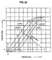
Fig. 22 is a graph showing the characteristics of the magnetostriction
characteristics of the magnetostriction oscillator assembled by the pre-loading.
Curve 1 is a magnetostriction curve in the state in which there is no magnetic bias
or external stress. Curves 2 to 4 are magnetostriction curves in the state in
which external stresses are applied. As the applied external stress increases,
the number of the curve increases. Vertical line A, A shows the value of the
magnetic bias by the permanent magnet or the direct current excitation.
Horizontal lines B, B and C, C shows the range of the strain to be controlled.
The value of the magnetic bias is to be set to the vertical line A, A of Fig. 1 when
positive and negative stress waves are to be generated, and to the vertical line D,
D when the stress is always positive or the stress is in the form of impulses.
The amount of external stress applied as a pre-load to the
magnetostriction oscillator should be equal to or larger than a magnetostriction
force corresponding to the maximum value of the magnetic field for controlling.
The external stress is determined on the basis of the cross-sectional area of the
stress-generating surface of the magnetostriction oscillator and the Young's
module and the contraction amount of the magnetostriction material. The
magnetostriction oscillator longer than that of the pocket by the amount of
contraction is cooled by a cryogenic coolant such as liquid nitrogen to shorten,
and the shortened oscillator is inserted into the pocket and then heated therein to
return the oscillator to its original length so that a static stress (pre-load) may
always be applied to the magnetostriction oscillator. When the magnetostriction
oscillator in this state is excited, the amount of strain of the oscillator generated
by the excitation is converted into a stress or a longitudinal elastic wave. On the
other hand, the magnetostriction material itself can generate only one way strain
of either positive (expansion) or negative (contraction). Therefore, in order to
generate an elastic wave in negative direction with the magnetostriction material
of the positive direction, a stress for the negative strain must be given in the
magnetostriction material. This stress is generated by a permanent magnet or a
flow of direct current excitation current through the excitation winding. Then,
when an excitation current is supplied to flow in the negative direction, the stress
decreases and thus a negative stress is generated. Thus, in order to control the
positive and negative stress or the longitudinal elastic wave, the adjustment and
the control of the magnetic characteristics of the magnetostriction oscillator is an
element. If the structure to be integrated has magnetic characteristics, the
characteristics of the magnetostriction oscillator, i. e., the control of the stress is
significantly affected, so that the structure for integrating is made of a non-magnetic
material.
Due to the application of a metallic magnetostriction material having
positive strain characteristics;
Due to the pre-loading by the cooling shrink-fitting;
While the present invention has been described as applied to the tubular
member of the drill string for use in the digging rig in the first to fourth
embodiments, the present invention should not be limited to such the tubular
member, but is equally applicable to a flat surface, such as iron plate, H-shaped
steel or the like. The device may be attached to one part of the iron frame of the
steel structure such as the bridge girder, building structural framework.
As has been described, an elastic wave generator of the present
invention comprises: an excitation coil; a magnetostriction oscillator around which
the excitation coil is wound and made of a lamination of magnetostriction sheets
having a metallic crystalline structure which exhibits positive strain characteristics
in which its length varies directionally upon magnetic excitation; and an oscillator
support having a first support surface shrink-fit against a first end surface of the
magnetostriction oscillator intersecting the direction along which the length of the
magnetostriction oscillator changes and a second support surface shrink-fit
against a second end surface of the magnetostriction oscillator intersecting the
direction along which the length of the magnetostriction oscillator changes,
whereby the changes in the length of the magnetostriction oscillator due to the
magnetic excitation of the excitation coil appearing at the first and second end
surfaces is directly supported by the first and second support surfaces.
Therefore, the elastic wave generator can be realized in which the generation
and the injection of a large stress wave that has not heretofore been solved.
According to the elastic wave generator mounting structure of the present
invention for mounting a magnetostriction oscillator to an object to which an
elastic wave is irradiated, the magnetostriction oscillator is inserted within the
hole or recess smaller than the magnetostriction oscillator so that the
magnetostriction oscillator is held in the state to which a pre-load is applied, so
that a pre-load much larger than that obtained by the conventional canti-levered
clamping screw.
Also, according to the method for mounting a magnetostriction oscillator
of the present invention, the pre-load is applied through the use of the expansion
and contraction force due to the temperature coefficient of the magnetostriction
material, a very large pre-load can be applied.
Also, according to the method for mounting the magnetostriction
oscillator of the present invention, the dimension of the hole or the recess is
made larger than the dimension when the magnetostriction oscillator is cooled by
the liquid nitrogen and is made smaller than the dimension when the magnetic
bias is applied at room temperature, so that the effect of the magnetostriction
deformation due to the magnetic bias can be utilized in generating the pre-load,
thereby increasing the pre-load.