EP1076231B1 - Device and method for determining unbalance - Google Patents
Device and method for determining unbalance Download PDFInfo
- Publication number
- EP1076231B1 EP1076231B1 EP00114139.9A EP00114139A EP1076231B1 EP 1076231 B1 EP1076231 B1 EP 1076231B1 EP 00114139 A EP00114139 A EP 00114139A EP 1076231 B1 EP1076231 B1 EP 1076231B1
- Authority
- EP
- European Patent Office
- Prior art keywords
- plate
- plane
- web
- axis
- unbalance
- Prior art date
- Legal status (The legal status is an assumption and is not a legal conclusion. Google has not performed a legal analysis and makes no representation as to the accuracy of the status listed.)
- Expired - Lifetime
Links
Images


Classifications
-
- G—PHYSICS
- G01—MEASURING; TESTING
- G01M—TESTING STATIC OR DYNAMIC BALANCE OF MACHINES OR STRUCTURES; TESTING OF STRUCTURES OR APPARATUS, NOT OTHERWISE PROVIDED FOR
- G01M1/00—Testing static or dynamic balance of machines or structures
- G01M1/02—Details of balancing machines or devices
- G01M1/04—Adaptation of bearing support assemblies for receiving the body to be tested
Definitions
- the invention relates to a device for determining the imbalance of a rotating body rotatably supported by a recording with a right angle to the axis of rotation arranged, the recording having, plate-shaped dynamometer element comprising an inner via webs connected to an outer frame member receiving plate and at least one between receiving plate and Frame member arranged vibration sensor which detects unbalance induced vibrations of the receiving plate relative to the frame member, web pairs are provided on both sides of the receptacle arranged webs, as well as a method for determining the imbalance of a rotating body, which is rotatably held by a recording of an unbalance detection device, with a recording having plate-shaped dynamometer element, in which the unbalance induced vibrations of Dynamometer Symposium Seten as translational vibrations and torsional vibrations are detected separately.
- a balancing machine which has a plate-shaped dynamometer element which is partially resiliently slotted and provided with webs.
- the inner plate has a receptacle for the rotary body, which is designed as a balancing spindle.
- the receiving plate is connected to both sides of the axis of the body of revolution in the plane of the plate arranged webs with the outer frame part of the dynamometer.
- the receiving plate is the vibrations resulting from the rotation of the rotating body vibration transducer on, of which one detects only the pivoting movement of the receiving plate about an axis corresponding to the imbalance component, which arises as a result of an unbalanced moment.
- an imbalance component resulting from an individual force is picked up by a further vibration converter whose measuring direction runs parallel to the plate plane.
- the dynamometer element is supported against a foundation.
- To support two flexible elastic flat springs and a further flexible elastic support are provided.
- the flat springs for absorbing forces in the direction of the axis of rotation are attached to both sides of the axis of the body of revolution on the receiving plate and extend at right angles away from the plate surface.
- In the known device are separate elements in the form of flexurally elastic supports for receiving forces acting in the axial direction, such.
- Axialschub- or weight forces provided, which can affect the oscillatory movements of the receiving plate and thus the accuracy of the unbalance determination in an undesirable manner.
- US 4,930,348 A is a vertical, hard-sprung balancing machine with a mounted on a machine table suspension cartridge known which has two spaced-apart spring plates which receive in bores the spindle housing of a balancing spindle.
- the spring plates have concentric slots to their holes, which are separated by two diametrically arranged resilient webs.
- the resilient webs of the two spring plates lie in the same plane containing the axis of rotation of the spindle.
- a force sensor is arranged to measure vibrations in the plate plane.
- the vibration signals of both force sensors by a static imbalance and an unbalance moment induced vibrations.
- the invention is therefore based on the object, a simple and inexpensive device for determining the imbalance of a To provide a rotating body that allows a disturbance free unbalance measurement and accurate evaluation of imbalance due to unbalance and static imbalance and in particular improves the accuracy in determining the static imbalance.
- the plate-shaped dynamometer element captures all the forces and moments emanating from the rotation body in itself, so that separate supports can be omitted in an advantageous manner.
- a device with a particularly compact design or height is obtained, which has a substantially symmetrical structure with regard to the stiffness distribution and the mass distribution and which, moreover, has one ensures particularly accurate unbalance determination due to improved level separation.
- the plate-shaped dynamometer element is particularly inexpensive, for example, as a sheet metal part by burning and forming or produced as a casting.
- the design according to the invention allows a very small distance of the rotor center of gravity from the reference plane of the dynamometer element, ie ultimately a more accurate result due to improved plane separation.
- the determination of the static imbalance is very accurate, since the structure is substantially symmetrical and the measurement plane of the vibration sensor is located in the plane of the plate of the dynamometer element.
- the embodiment according to the invention is particularly advantageous for the single-plane balancing.
- the pivot axis for the torsional vibrations of the dynamometer element is optimally positioned.
- the pivot axis formed by this pair of webs lies in the plane of the plate, so that no disturbing forces or moments can influence the measurement result.
- This pair of webs takes over by its rigid configuration in the simplest way, the support not unbalanced forces such as the weight or the forces, for example, in the axial direction of the rotating body due to the design of the rotor with axial force generating elements, such as rotor blades arise.
- the webs of this web pair have a high area moment of inertia about the transverse axis, which is the case, for example, in the case of a rectangular profile or two spaced webs forming a web.
- the invention allows in the simplest way the arrangement of the plate plane of the dynamometer in both the horizontal and in the vertical direction, so that special needs adapted balancing machines with vertical or horizontal axis of rotation can be realized very easily.
- the axis of rotation is arranged in an embodiment of the invention in the vertical direction and the plate plane thus extends in the horizontal, one obtains advantageously the possibility of the separate supporting elements free space below the dynamometer element for other elements of a balancing machine or an unbalance, e.g. for drive and control devices or also for clamping devices for fixing the rotating body to e.g. a balancing spindle or the receiving surfaces, resulting in an overall compact and service-friendly construction.
- dynamometer element 1 of a balancing machine not shown on an inner provided with a receptacle 2 for a rotary body 3 receiving plate 4 and an outer frame part 5, which are connected via web pairs 6 and 7, 7 'with each other.
- Dynamometer is understood in the balancing technique, a resilient support and measuring system.
- the receptacle 2 is fixed in a bore of the receiving plate 4 and may, for example, also have a balancing spindle, on which a rotational body 3 to be balanced can be mounted.
- the receptacle 2 receiving surfaces on which the rotary body 3 is attached.
- the receptacle 2 is driven in a conventional manner, for example via a belt drive or a flanged motor.
- the dynamometer element 1 is attached to the outer frame part 5 in the balancing machine and has two vibration sensors 11, 12, the signals of an unbalance measuring device for determining the imbalance compensation in two balancing planes by size and, taking into account the signals of a reference angle sensor, not shown, also fed to angular position become.
- the Vibration sensors can be, for example, electrodynamic speed sensors or piezo pickups.
- the unbalance induced vibrations of the receiving plate 4 are converted into translational oscillations and torsional vibrations.
- the conversion takes place in that the axis of rotation 8 of the rotary body 3, which extends at right angles to the plane of the plate receiving plate 4, is rotatable or pivotable about a lying in the median plane of the plate-shaped dynamometer element 1 pivot axis 10.
- the pivot axis 10 penetrates the axis of rotation 8 at right angles and, in the illustrated example, is arranged at right angles to the direction in which the unbalance-induced translatory vibrations are detected.
- it is also possible to determine the direction for detecting the translational vibrations e.g. to arrange in the direction of the pivot axis 10.
- the unbalance-induced torsional vibrations about the pivot axis 10 result from the unbalance moment of the rotating body to be examined.
- Imbalance-induced translational vibrations of the receiving plate 4 are caused by the static imbalance of the rotary body 3 and take place in a plane perpendicular to the axis of rotation 8 level.
- Einbenenauswuchtung only the signal of the translational oscillations detecting vibration sensor 12 is required; so that the torsional vibration detecting vibration sensor 11 can be omitted in single-plane machines.
- a web pair 6 is arranged in the pivot axis 10 for the rotational movement of the receiving plate 4 and equidistant thereto are two pairs of webs 7, 7 'at the ends of the longitudinal side of the example in plan view
- the arrangement of the web pair 6 in the pivot axis 10, the unbalance induced rotational movement of the receiving plate 4 is practically not affected, since no disturbance torque can arise.
- the arrangement of the second pair of webs 7, 7 ', together with that of the first pair of webs 6, constitutes a parallel link arrangement for vibrations of the receiving plate 4 in a direction perpendicular to the pivot axis 10.
- the two outer pairs of webs 7, 7' are bendable both in terms of bends the plate plane out due to the torsional vibrations of the receiving plate 4 as well as with respect to bends due to their parallel link function.
- the pair of webs 6 extending in the pivot axis 10 is flexible in terms of its parallel link function, but rigid with respect to bends out of the plane of the plate; This flexural rigidity allows the removal of all, that is, the non-unbalanced forces such as axial forces caused by the rotor or weight forces in the dynamometer element 1 itself, without additional support elements are required.
- a vibration sensor 11 For detecting the torsional vibrations of the receiving plate 4 about the pivot axis 10, a vibration sensor 11 is provided which is formed in the example as Tauchspulenaufsacrificing and whose measuring axis is parallel to the axis of rotation 8 of the rotary body 3.
- the vibration sensor 11 is fixed in the example shown on a recessed on the outer frame part 5 extension 13.
- an integrally formed on the receiving plate 4 plate extension 14 is movable and transmits over a flexurally elastic coupling rod 15, the unbalance induced torsional vibrations on the vibration sensor 11.
- it can also provide an arrangement with an offset in the plate extension and in the otherwise planar running frame part or both parts may have an offset in the vertical direction.
- the measuring axis of the vibration sensor 12 provided for detecting the translational vibrations is at right angles to the web axes and the axis of rotation 8 of the rotary body 3 and in the median plane of the plate-shaped dynamometer 1.
- the vibration sensor 12 is arranged in the recess shown on the outer frame circumference in the illustrated embodiment and protrudes a flexurally elastic coupling rod 16 with the narrow side of the receiving plate 4 in conjunction.
- the axis of at least one of the two vibration sensors 11, 12 can be parallel-displaced and the transducer is then attached.
- this can be accomplished by moving the transducer with its flange on the associated frame surface at the bottom of the recess on the outer frame circumference. It can be so mechanically eliminate any possible phase error of the two pickup signals, for example due to material anisotropies or manufacturing asymmetries.
- piezo pickups which are arranged directly between the receiving plate and the frame part, can be provided and geometrically provides a higher degree of symmetry of the device. Further, you can order pickup for detecting the pivotal movements on both sides of the pivot axis, which further improves the degree of symmetry.
- Similar recesses 21 in the offset by 90 ° surfaces can serve as adjustment for the mobility of the receiving plate 4 in terms of translational vibrations. In Fig. 4 this is exemplified for the pair of webs 6 forming the pivot axis.
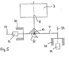
- the rotary body 3 is rotatably mounted with its axis of rotation 8 about the horizontal pivot axis 10; the axis of rotation 8 and the receiving plate 4 can be illustrated by an angle lever with mutually perpendicular lever arms.
- the dynamometer system has a horizontal stiffness indicated by the spring symbol 30, a vertical stiffness indicated by the spring symbol 31, and a rotational rigidity arranged by the rotary spring symbol 32.
- the dash-dotted line 33 shows the active plane of the vibration pickup 11 for the vertical direction, the dotted line 34, the active plane of the vibration pickup 12 for the horizontal direction.
- the horizontal vibration sensor 12 measures the vibration path in the horizontal direction due to the static imbalance.
- the pivot axis 10 remains in the working plane 34 of the horizontal vibration sensor 12, i. in the median plane of the plate-shaped dynamometer.
- the horizontal vibration sensor 12 measures the vibration path in the horizontal direction due to the static unbalance, while the vertical vibration sensor by the pivotal movement of the bell crank assembly. 8 4 measures vibration displacement resulting from the moment unbalance in the vertical direction.
- the pivot axis 10 remains in the active plane 34 of the horizontal vibration 12th
- the pivot axis 10 of this system is no longer in the working plane of the horizontal vibration sensor 12, but outside, resulting in the measurement of e.g. leads to large vibration paths.
Description
Die Erfindung bezieht sich auf eine Einrichtung zur Ermittlung der Unwucht eines von einer Aufnahme rotierbar gehaltenen Rotationskörpers mit einem rechtwinklig zur Rotationsachse angeordneten, die Aufnahme aufweisenden, plattenförmigen Dynamometerelement, das eine innere über Stege mit einem äußeren Rahmenteil verbundene Aufnahmeplatte umfaßt sowie zumindest einen zwischen Aufnahmeplatte und Rahmenteil angeordneten Schwingungsaufnehmer, der unwuchtinduzierte Schwingungen der Aufnahmeplatte gegenüber dem Rahmenteil erfaßt, wobei Stegpaare aus beiderseits der Aufnahme angeordneten Stegen vorgesehen sind, sowie auf ein Verfahren zur Ermittlung der Unwucht eines Rotationskörpers, der von einer Aufnahme einer Unwuchtermittlungseinrichtung rotierbar gehalten wird, mit einem die Aufnahme aufweisenden plattenförmigen Dynamometerelement, bei dem die unwuchtinduzierten Schwingungen von Dynamometerbereichen als Translationsschwingungen und Drehschwingungen getrennt erfaßbar sind.The invention relates to a device for determining the imbalance of a rotating body rotatably supported by a recording with a right angle to the axis of rotation arranged, the recording having, plate-shaped dynamometer element comprising an inner via webs connected to an outer frame member receiving plate and at least one between receiving plate and Frame member arranged vibration sensor which detects unbalance induced vibrations of the receiving plate relative to the frame member, web pairs are provided on both sides of the receptacle arranged webs, as well as a method for determining the imbalance of a rotating body, which is rotatably held by a recording of an unbalance detection device, with a recording having plate-shaped dynamometer element, in which the unbalance induced vibrations of Dynamometerbereichen as translational vibrations and torsional vibrations are detected separately.
Aus der
Aus
Der Erfindung liegt daher die Aufgabe zugrunde, eine einfache und kostengünstige Einrichtung zur Ermittlung der Unwucht eines Rotationskörpers zu schaffen, die eine störeinflußfreie Unwuchtmessung und eine genaue Auswertung der Unwuchtanteile aufgrund von Unwuchtmoment und statischer Unwucht ermöglicht und die insbesondere die Genauigkeit bei der Ermittlung der statischen Unwucht verbessert.The invention is therefore based on the object, a simple and inexpensive device for determining the imbalance of a To provide a rotating body that allows a disturbance free unbalance measurement and accurate evaluation of imbalance due to unbalance and static imbalance and in particular improves the accuracy in determining the static imbalance.
Erfindungsgemäß wird diese Aufgabe durch die Merkmale des unabhängigen Patentanspruchs 1 gelöst. Bei der erfindungsgemäßen Einrichtung fängt das plattenförmige Dynamometerelement alle vom Rotationskörper ausgehenden Kräfte und Momente in sich ab, so daß gesonderte Abstützungen in vorteilhafter Weise entfallen können. Auf einfachste Weise erhält man durch Ausgestaltungen der Stegpaare sowohl für die Axialschub- oder Gewichtskraftabstützung als auch für die schwingfähige Abstützung eine Einrichtung mit besonders kompakter Bauform bzw. Bauhöhe die einen im Hinblick auf die Steifigkeitsverteilung und die Massenverteilung im wesentlichen symmetrischen Aufbau aufweist und die darüberhinaus eine besonders genaue Unwuchtermittlung aufgrund verbesserter Ebenentrennung sicherstellt. Das plattenförmige Dynamometerelement ist besonders kostengünstig z.B. als Blechteil durch Ausbrennen und Umformen oder als Gußteil herstellbar. Die erfindungsgemäße Bauform ermöglicht einen sehr geringen Abstand des Rotorschwerpunkts von der Bezugsebene des Dynamometerelements, d.h. letztendlich aufgrund verbesserter Ebenentrennung ein genaueres Ergebnis. Die Bestimmung der statischen Unwucht erfolgt sehr genau, da der Aufbau im wesentlichen symmetrisch ist und die Meßebene des Schwingungsaufnehmers in der Plattenebene des Dynamometerelements liegt. Die Ausgestaltung nach der Erfindung ist speziell für die Einebenenauswuchtung vorteilhaft.According to the invention this object is solved by the features of
Durch die Anordnung des ersten Stegpaares in der Plattenebene und in einer die Rotationsachse enthaltenden Ebene gemäß einer Ausgestaltung der Erfindung ist die Schwenkachse für die Drehschwingungen des Dynamometerelements optimal positioniert. Die durch dieses Stegpaar gebildete Schwenkachse liegt in der Plattenebene, so daß keine störenden Kräfte oder Momente das Meßergebnis beeinflussen können. Dieses Stegpaar übernimmt durch seine biegesteife Ausgestaltung auf einfachste Weise die Abstützung nicht unwuchtinduzierter Kräfte wie z.B. der Gewichtskraft oder der Kräfte, die z.B. in Achsrichtung des Rotationskörpers aufgrund der Ausgestaltung des Rotors mit Axialkraft erzeugenden Elementen, z.B. Rotorschaufeln, entstehen. Die Stege dieses Stegpaares weisen hierzu ein hohes Flächenträgheitsmoment um die Querachse auf, was z.B. bei einem Rechteckprofil oder bei zwei, einen Steg bildenden, beabstandeten Stäben der Fall ist.Due to the arrangement of the first pair of webs in the plate plane and in a plane containing the axis of rotation according to an embodiment of the invention, the pivot axis for the torsional vibrations of the dynamometer element is optimally positioned. The pivot axis formed by this pair of webs lies in the plane of the plate, so that no disturbing forces or moments can influence the measurement result. This pair of webs takes over by its rigid configuration in the simplest way, the support not unbalanced forces such as the weight or the forces, for example, in the axial direction of the rotating body due to the design of the rotor with axial force generating elements, such as rotor blades arise. For this purpose, the webs of this web pair have a high area moment of inertia about the transverse axis, which is the case, for example, in the case of a rectangular profile or two spaced webs forming a web.
Ordnet man in weiterer Ausgestaltung der Erfindung beiderseits des die Schwenkachse bildenden Stegpaares zwei weitere parallel laufende Stegpaare an, so ergibt sich eine sowohl hinsichtlich der Auslegung als auch hinsichtlich der Herstellung, der Kalibrierung und der Meßgenauigkeit besonders vorteilhafte symmetrische Ausführungsform. Dieses gilt auch für eine Weiterbildung der Erfindung, bei der die Aufnahmeplatte rechteckförmig ausgebildet ist und die Stegpaare an den Enden sowie in der Mitte der längeren Rechteckseite angeordnet sind.Assigning in a further embodiment of the invention on both sides of the pivot axis forming web pair two more parallel web pairs, so there is a particularly advantageous in terms of both design and in terms of manufacturing, calibration and accuracy of measurement symmetrical embodiment. This also applies to a development of the invention, in which the receiving plate is rectangular and the web pairs are arranged at the ends and in the middle of the longer side of the rectangle.
Die Ausgestaltung nach den Merkmalen des Patentanspruchs 12 ergibt ein sehr kompaktes, genau messendes Dynamometerelement.The embodiment according to the features of
Die Erfindung läßt auf einfachste Weise die Anordnung der Plattenebene des Dynamometerelements sowohl in horizontaler als auch in vertikaler Richtung zu, so daß speziellen Bedürfnissen angepaßte Auswuchtmaschinen mit vertikaler oder horizontaler Rotationsachse sich sehr einfach verwirklichen lassen.The invention allows in the simplest way the arrangement of the plate plane of the dynamometer in both the horizontal and in the vertical direction, so that special needs adapted balancing machines with vertical or horizontal axis of rotation can be realized very easily.
Wird die Rotationsachse in Ausgestaltung der Erfindung in vertikaler Richtung angeordnet und verläuft die Plattenebene damit in der Horizontalen, erhält man in vorteilhafter Weise die Möglichkeit, den von gesonderten Abstützelementen freien Raum unterhalb des Dynamometerelements für weitere Elemente einer Auswuchtmaschine bzw. einer Unwuchtmeßmaschine z.B. für Antriebs- und Steuerungseinrichtungen oder auch für Spanneinrichtungen für die Befestigung des Rotationskörpers auf z.B. einer Wuchtspindel oder den Aufnahmeflächen zu nutzen, was insgesamt zu einem kompakten und servicefreundlichen Aufbau führt.If the axis of rotation is arranged in an embodiment of the invention in the vertical direction and the plate plane thus extends in the horizontal, one obtains advantageously the possibility of the separate supporting elements free space below the dynamometer element for other elements of a balancing machine or an unbalance, e.g. for drive and control devices or also for clamping devices for fixing the rotating body to e.g. a balancing spindle or the receiving surfaces, resulting in an overall compact and service-friendly construction.
Weitere vorteilhafte Ausführungsformen ergeben sich aus den Unteransprüchen und aus der nachfolgenden Beschreibung.Further advantageous embodiments will become apparent from the subclaims and from the following description.
Die Erfindung wird nachstehend mit Bezug auf die Zeichnung näher erläutert. Es zeigen:
- Fig. 1
- das Dynamometerelement in perspektivischer Darstellung,
- Fig. 2
- eine Schnittdarstellung längs der Linie II-II
- Fig. 3
- eine Schnittdarstellung längs der Linie III-III
- Fig. 4
- einen Steg in Draufsicht
- Fig. 5
- eine Prinzipdarstellung der erfindungsgemäßen Einrichtung
- Fig. 1
- the dynamometer element in perspective view,
- Fig. 2
- a sectional view taken along the line II-II
- Fig. 3
- a sectional view taken along the line III-III
- Fig. 4
- a jetty in top view
- Fig. 5
- a schematic diagram of the device according to the invention
Nach
Die unwuchtinduzierten Schwingungen der Aufnahmeplatte 4 werden in translatorische Schwingungen und Drehschwingungen umgewandelt. Die Umwandlung erfolgt dadurch, daß die Rotationsachse 8 des Rotationskörpers 3, die rechtwinklig zur Plattenebene der Aufnahmeplatte 4 verläuft, um eine in der Mittelebene des plattenförmigen Dynamometerelements 1 liegende Schwenkachse 10 drehbar bzw. schwenkbar ist. Die Schwenkachse 10 durchdringt die Rotationsachse 8 rechtwinklig und ist im dargestellten Beispiel rechtwinklig zu der Richtung, in der die unwuchtinduzierten Translationsschwingungen erfaßt werden, angeordnet. Es ist jedoch auch möglich, die Richtung zur Erfassung der Translationsschwingungen z.B. in Richtung der Schwenkachse 10 anzuordnen. Die unwuchtinduzierten Drehschwingungen um die Schwenkachse 10 resultieren aus dem Unwuchtmoment des zu untersuchenden Rotationskörpers. Unwuchtinduzierte translatorische Schwingungen der Aufnahmeplatte 4 werden durch die statische Unwucht des Rotationskörpers 3 hervorgerufen und erfolgen in einer senkrecht zur Rotationsachse 8 liegenden Ebene. Bei der Einebenenauswuchtung wird lediglich das Signal des die translatorischen Schwingungen erfassenden Schwingungsaufnehmers 12 benötigt; so daß der die Drehschwingungen erfassende Schwingungsaufnehmer 11 bei Einebenenmaschinen entfallen kann.The unbalance induced vibrations of the
Die Anordnung und Auslegung der Stegpaare 6 und 7, 7' stellt das im wesentlichen unbeeinflußte unwuchtinduzierte Translations- und Drehverhalten der Aufnahmeplatte 4 in Bezug auf das äußere Rahmenteil 5 sicher. Hierzu ist ein Stegpaar 6 in der Schwenkachse 10 für die Drehbewegung der Aufnahmeplatte 4 angeordnet und äquidistant hierzu sind zwei Stegpaare 7, 7' an den Enden der Längsseite der im Beispiel in der Draufsicht rechteckförmigen Aufnahmeplatte 4 angeordnet und erstrecken sich in Richtung der Erstreckung des ersten Stegpaares 6. Durch die Anordnung des Stegpaares 6 in der Schwenkachse 10 wird die unwuchtinduzierte Drehbewegung der Aufnahmeplatte 4 praktisch nicht beeinflußt, da kein Störmoment entstehen kann. Die Anordnung des zweiten Stegpaares 7, 7' stellt zusammen mit der des ersten Stegpaares 6 eine Parallellenkeranordnung für Schwingungen der Aufnahmeplatte 4 in einer senkrecht zur Schwenkachse 10 liegenden Richtung dar. Die beiden äußeren Stegpaare 7, 7' sind biegeweich sowohl in Bezug auf Biegungen aus der Plattenebene heraus aufgrund der Drehschwingungen der Aufnahmeplatte 4 als auch in Bezug auf Biegungen aufgrund ihrer Parallellenkerfunktion. Das in der Schwenkachse 10 verlaufende Stegpaar 6 ist biegeweich im Hinblick auf seine Parallellenkerfunktion, aber biegesteif in Bezug auf Biegungen aus der Plattenebene heraus; diese Biegesteifigkeit ermöglicht die Abtragung aller, d.h. auch der nicht unwuchtinduzierten Kräfte wie rotorbedingte Axialkräfte oder Gewichtskräfte im Dynamometerelement 1 selbst, ohne daß zusätzliche Abstützelemente erforderlich sind.The arrangement and design of the web pairs 6 and 7, 7 'ensures the substantially uninfluenced unbalance induced translational and rotational behavior of the receiving
Zur Erfassung der Drehschwingungen der Aufnahmeplatte 4 um die Schwenkachse 10 ist ein Schwingungsaufnehmer 11 vorgesehen, der im Beispiel als Tauchspulenaufnehmer ausgebildet ist und dessen Meßachse parallel zur Rotationsachse 8 des Rotationskörpers 3 verläuft. Der Schwingungsaufnehmer 11 ist im dargestellten Beispiel an einem am äußeren Rahmenteil 5 vertieft angeformten Fortsatz 13 befestigt. In dieser Vertiefung ist ein an der Aufnahmeplatte 4 angeformter Plattenfortsatz 14 bewegbar und überträgt über eine biegeelastische Koppelstange 15 die unwuchtinduzierten Drehschwingungen auf den Schwingungsaufnehmer 11. Es kann jedoch auch eine Anordnung mit einem Versatz im Plattenfortsatz und im ansonsten eben verlaufenden Rahmenteil vorgesehen werden oder beide Teile können einen Versatz in Vertikalrichtung aufweisen.For detecting the torsional vibrations of the receiving
Die Meßachse des zur Erfassung der translatorischen Schwingungen vorgesehenen Schwingungsaufnehmers 12 liegt rechtwinklig zu den Stegachsen und der Rotationsachse 8 des Rotationskörpers 3 und in der Mittelebene des plattenförmigen Dynamometers 1. Der Schwingungsaufnehmer 12 ist in dem dargestellten Ausführungsbeispiel in einer Vertiefung am äußeren Rahmenumfang angeordnet und steht über eine biegeelastische Koppelstange 16 mit der Schmalseite der Aufnahmeplatte 4 in Verbindung.The measuring axis of the
Nicht näher dargestellt ist eine Ausführungsform, bei der die Achse zumindest eines der beiden Schwingungsaufnehmer 11, 12 parallelverschoben werden kann und der Aufnehmer dann befestigt wird. Bei dem Schwingungsaufnehmer 12 läßt sich dies durch Verschieben des Aufnehmers mit seiner Flanschfläche auf der zugeordneten Rahmenfläche am Boden der Vertiefung am äußeren Rahmenumfang bewerkstelligen. Es lassen sich so eventuelle Phasenfehler der beiden Aufnehmersignale beispielsweise aufgrund von Werkstoffanisotropien oder Herstellungsunsymmetrien auf einfache Weise mechanisch beseitigen.Not shown in detail is an embodiment in which the axis of at least one of the two
Auch die Verwendung von Piezoaufnehmern, die unmittelbar zwischen der Aufnahmeplatte und dem Rahmenteil angeordnet werden, kann vorgesehen werden und liefert geometrisch betrachtet einen höheren Symmetriegrad der Einrichtung. Ferner kann man Aufnehmer zur Erfassung der Schwenkbewegungen beiderseits der Schwenkachse anordnen, was den Symmetriegrad weiter verbessert. Als Einstellmöglichkeit für die Drehsteifigkeit des Dynamometerelements 1 sind, wie aus
Wie aus der
Bei einer Einebenenmessung, also der Ermittlung einer statischen Unwucht, mißt der horizontale Schwingungsaufnehmer 12 den Schwingweg in horizontaler Richtung aufgrund der statischen Unwucht. Die Schwenkachse 10 bleibt dabei in der Wirkebene 34 des horizontalen Schwingungsaufnehmers 12, d.h. in der Mittelebene des plattenförmigen Dynamometers.In a single plane measurement, ie the determination of a static unbalance, the
Bei einer Zweiebenenmessung, also der Ermittlung einer dynamischen Unwucht, die als Überlagerung einer statischen Unwucht und einer Momentenunwucht betrachtet werden kann, mißt der horizontale Schwingungsaufnehmer 12 den Schwingweg in horizontaler Richtung aufgrund der statischen Unwucht, während der vertikale Schwingungsaufnehmer den durch die Schwenkbewegung der Winkelhebelanordnung 8, 4 aufgrund der Momentenunwucht sich ergebenden Schwingweg in vertikaler Richtung mißt. Die Schwenkachse 10 bleibt dabei in der Wirkebene 34 des horizontalen Schwingungsaufnehmers 12.In a two-level measurement, ie the determination of a dynamic imbalance, which can be regarded as a superposition of static imbalance and a moment unbalance, the
Bei einem von Störeinflüssen z.B. aufgrund zusätzlicher Abstützungen beeinflußten System, das im Vergleich zum erfindungsgemäßen System nur einen geringen Symmetriegrad im Hinblick auf die Massenverteilung und die Steifigkeitsverteilung aufweist, liegt die Schwenkachse 10 dieses Systems nicht mehr in der Wirkebene des horizontalen Schwingungsaufnehmers 12, sondern außerhalb, was zur Messung von z.B. zu großen Schwingwegen führt.In case of any interference, e.g. Due to additional supports influenced system, which has compared to the inventive system only a small degree of symmetry in terms of mass distribution and stiffness distribution, the
Mit der Erfindung ist erstmals sichergestellt, daß die Schwenkachse d.h. die Bezugsebene des plattenförmigen Dynamometerelements 1 in der Wirkebene 34 des horizontalen Schwingungsaufnehmers 12 bleibt, so daß eine ideale Trennung der von einer dynamischen Unwucht induzierten Schwenkbewegungen und damit eine genaue Unwuchtermittlung der statischen Unwucht erfolgt.With the invention it is first ensured that the pivot axis i. the reference plane of the plate-shaped
Claims (11)
- An unbalance measuring device for determining the unbalance of a rotary body (3), with a plate-shaped dynamometer element (1) arranged at right angles to said body's axis of rotation (8) and including a mounting fixture (2) which supports the rotary body (3) to enable rotation about its axis of rotation (8) and is adapted to be driven in conventional manner by a motor, and comprising an inner mounting plate (4) connected to an outer frame member (5) by means of web members, as well as at least two vibration sensors (11, 12) arranged between the mounting plate (4) and the frame member (5) for detecting any unbalance-induced vibrations of the mounting plate (4) relative to the frame member (5), with a first one of said vibrations sensors (11, 12) being arranged in the plane of the plate to detect vibrations in the plane of the plate, there being arranged on either side of the mounting plate (4) web pairs (6, 7, 7') constructed to support non-unbalance-induced forces of the mounting plate (4) and to support the mounting plate (4) in a manner enabling it to vibrate, and wherein a first pair of webs (6) extends in a plane containing the axis of rotation (8) and in the plane of the plate, characterized in that the first web pair (6) defines a pivot axis (10) arranged at right angles to the axis of ro tation (8) for a rotary motion of the mounting plate (4) and exhibits, for supporting the non-unbalance-induced forces, a profile that is flexurally stiff relative to flexure out of the plane of the plate and flexurally soft in the direction of the plane of the plate, and that second web pairs (7, 7') arranged equidistantly on either side of the first web pair (6) extend in the plane of the plate and in the direction of extension of the first web pair (6), said second web pairs exhibiting a profile that is flexurally soft relative to flexure out of the plane of the plate and in the direction of the plane of the plate, and that a second one of the vibration sensors (11, 12) detects the unbalance-induced vibrations of the mounting plate (4) relative to the frame member (5) essentially at right angles to the plane of the plate.
- The device according to claim 1, characterized in that the flexurally stiff profile of the first web pair (6) defining the pivot axis (10) is a rectangular profile, with the long side of the rectangle extending perpendicularly to the plane of the plate.
- The device according to claim 1, characterized in that the second web pairs (7, 7') extending parallel to each other have a flexurally soft profile shaped in a square, polygonal or circular configuration.
- The device according to one or several ones of the preceding claims, characterized in that the mounting plate (4) is of a rectangular configuration and the first web pairs (6) are arranged in the center and the second web pairs (7, 7') at the ends of the long side of the rectangle.
- The device according to one or several ones of the preceding claims, characterized in that the parallel extending second web pairs (7, 7') include recesses (20) to improve their flexural property in a direction perpendicular to the plane of the plate.
- The device according to one or several ones of the preceding claims, characterized in that one or several ones of the first or second web pairs (6, 7, 7') include recesses (21) to improve their flexural property in the plane of the plate.
- The device according to one or several ones of the preceding claims, characterized in that a vibration sensor (11) detecting the pivotal motion (10) is supported in a socket of the frame member (5) at the end of an extension of the frame member (5).
- The device according to one or several ones of the preceding claims, characterized in that at least one vibration sensor (11, 12) is attachable in a manner displaced parallel to its axis.
- The device according to one or several ones of the preceding claims, characterized in that vibration sensors detecting the pivotal motion are arranged in the form of piezo elements equidistantly on either side of the pivot axis (10).
- The device according to one or several ones of the preceding claims, characterized in that, for coupling the vibration sensors (11, 12), elastic, preferably flexurally elastic coupling elements (15, 16, 16') are provided between the mounting plate (4) and the vibration sensors (11, 12).
- The device according to one or several ones of the preceding claims, characterized in that the axis of rotation (8) of the rotary body (3) extends in a vertical direction.
Applications Claiming Priority (2)
| Application Number | Priority Date | Filing Date | Title |
|---|---|---|---|
| DE19937495A DE19937495A1 (en) | 1999-08-07 | 1999-08-07 | Device and method for determining the unbalance |
| DE19937495 | 1999-08-07 |
Publications (3)
| Publication Number | Publication Date |
|---|---|
| EP1076231A2 EP1076231A2 (en) | 2001-02-14 |
| EP1076231A3 EP1076231A3 (en) | 2003-01-15 |
| EP1076231B1 true EP1076231B1 (en) | 2016-08-17 |
Family
ID=7917697
Family Applications (1)
| Application Number | Title | Priority Date | Filing Date |
|---|---|---|---|
| EP00114139.9A Expired - Lifetime EP1076231B1 (en) | 1999-08-07 | 2000-07-10 | Device and method for determining unbalance |
Country Status (4)
| Country | Link |
|---|---|
| US (1) | US6779400B1 (en) |
| EP (1) | EP1076231B1 (en) |
| JP (1) | JP3990098B2 (en) |
| DE (1) | DE19937495A1 (en) |
Families Citing this family (14)
| Publication number | Priority date | Publication date | Assignee | Title |
|---|---|---|---|---|
| DE102004056367B4 (en) * | 2004-11-22 | 2015-07-02 | Schenck Rotec Gmbh | Bearing device for a device for determining the imbalance and the nonuniformity of a rotating body |
| US8272265B2 (en) * | 2005-07-12 | 2012-09-25 | Technion Research And Development Foundation Ltd. | System and method for active detection of asymmetry in rotating structures |
| ITMI20061000A1 (en) * | 2006-05-22 | 2007-11-23 | Milano Politecnico | ELASTIC COUPLING WITH SPHERICAL HINGE TRANSLATOR AND SENSOR OF FORCES AND MOMENTS PERFECTED WITH THIS JOINT |
| US7775107B2 (en) * | 2007-10-03 | 2010-08-17 | Hamilton Sundstrand Corporation | Measuring rotor imbalance via blade clearance sensors |
| ITMI20130343A1 (en) | 2013-03-07 | 2014-09-08 | Carlo Buzzi | DEVICE FOR WHEEL BALANCING. |
| CN103604563B (en) * | 2013-12-01 | 2016-02-17 | 北京航空航天大学 | A kind of magnetic suspension rotor amount of unbalance on-line identification method based on electric current test mass |
| CN104764551B (en) * | 2015-04-14 | 2017-08-04 | 南京理工大学 | A kind of unbalance dynamic momentum test device |
| US9816899B2 (en) | 2015-07-24 | 2017-11-14 | Snap-On Equipment Srl A Unico Socio | Communication system for a tyre service machine and measuring unit for being used with such communication system |
| US9829407B2 (en) | 2015-07-24 | 2017-11-28 | Snap-On Equipment Srl A Unico Socio | Measuring unit and measuring assembly for measuring unbalance forces |
| EP3121578B1 (en) * | 2015-07-24 | 2023-05-10 | Snap-on Equipment Srl a unico socio | Communication system for a tyre service machine and measuring unit for being used with such communication system |
| EP3121577B1 (en) * | 2015-07-24 | 2020-02-12 | Snap-on Equipment Srl a unico socio | Measuring unit and measuring assembly for measuring unbalance forces |
| AU2017365703B2 (en) * | 2016-11-24 | 2022-09-08 | The University Of Queensland | Force sensing device |
| CN111157107B (en) * | 2020-02-05 | 2021-11-30 | 山东联合电力产业发展有限公司 | High-stability generator swing measuring device |
| CN112834091A (en) * | 2020-12-31 | 2021-05-25 | 苏州大学 | Micro-force sensor for micro-assembly and piezoelectric ceramic driving micro-gripper |
Citations (2)
| Publication number | Priority date | Publication date | Assignee | Title |
|---|---|---|---|---|
| GB1388047A (en) * | 1971-03-22 | 1975-03-19 | Dunlop Ltd | Uniformity testing machines |
| US4930348A (en) * | 1988-11-25 | 1990-06-05 | Balance Engineering Corporation | Vertical balancing machine with cartridge assembly |
Family Cites Families (11)
| Publication number | Priority date | Publication date | Assignee | Title |
|---|---|---|---|---|
| DE1237807B (en) * | 1961-10-13 | 1967-03-30 | Schenck Gmbh Carl | Balancing machine |
| DE1937865B2 (en) * | 1969-07-25 | 1974-05-16 | Carl Schenck Maschinenfabrik Gmbh, 6100 Darmstadt | Storage racks for balancing machines |
| DE2114770B1 (en) * | 1971-03-26 | 1972-06-29 | Gebr Hofmann Kg Maschinenfabrik | Device for balancing unbalanced bodies |
| DE2608891C2 (en) * | 1976-03-04 | 1979-11-29 | Carl Schenck Ag, 6100 Darmstadt | Spring arrangement for the oscillating support of the recirculating body bearing in a balancing machine |
| DE2847295C2 (en) | 1978-10-31 | 1983-02-03 | Schenck Auto-Service-Geräte GmbH, 6100 Darmstadt | Device for determining the unbalance of a rotating body held by a receptacle of a balancing machine with a bearing stand |
| DE2942379A1 (en) * | 1979-10-19 | 1981-04-23 | Gebr. Hofmann Gmbh & Co Kg Maschinenfabrik, 6100 Darmstadt | Balancing rotating body in two or more planes - is by measuring oscillator of rod spring mounted bearings |
| DE3330974C2 (en) * | 1983-08-27 | 1986-07-24 | Hofmann Werkstatt-Technik GmbH, 6102 Pfungstadt | Device for determining the static unbalance of a test piece |
| US4640138A (en) * | 1985-03-06 | 1987-02-03 | Mts Systems Corporation | Multiple axis load sensitive transducer |
| EP0381712B1 (en) * | 1988-07-18 | 1992-03-04 | Wirth Gallo Messtechnik Ag | A mass and force meter with elastic reduction |
| US5677487A (en) * | 1995-10-13 | 1997-10-14 | A/S Bruel & Kjaer | Method and apparatus for measuring acceleration or mechanical forces |
| US5784929A (en) * | 1996-09-10 | 1998-07-28 | Illinois Tool Works Inc. | Dynamometer torsional damping apparatus |
-
1999
- 1999-08-07 DE DE19937495A patent/DE19937495A1/en not_active Withdrawn
-
2000
- 2000-07-10 EP EP00114139.9A patent/EP1076231B1/en not_active Expired - Lifetime
- 2000-08-07 US US09/633,681 patent/US6779400B1/en not_active Expired - Fee Related
- 2000-08-07 JP JP2000239018A patent/JP3990098B2/en not_active Expired - Fee Related
Patent Citations (2)
| Publication number | Priority date | Publication date | Assignee | Title |
|---|---|---|---|---|
| GB1388047A (en) * | 1971-03-22 | 1975-03-19 | Dunlop Ltd | Uniformity testing machines |
| US4930348A (en) * | 1988-11-25 | 1990-06-05 | Balance Engineering Corporation | Vertical balancing machine with cartridge assembly |
Also Published As
| Publication number | Publication date |
|---|---|
| JP3990098B2 (en) | 2007-10-10 |
| JP2001074584A (en) | 2001-03-23 |
| US6779400B1 (en) | 2004-08-24 |
| EP1076231A3 (en) | 2003-01-15 |
| EP1076231A2 (en) | 2001-02-14 |
| DE19937495A1 (en) | 2001-02-08 |
Similar Documents
| Publication | Publication Date | Title |
|---|---|---|
| EP1076231B1 (en) | Device and method for determining unbalance | |
| EP1376086B1 (en) | Torque sensor | |
| EP1108204B1 (en) | Rotor imbalance measuring devices with at least one virtual bearing point | |
| EP2944966B1 (en) | Vibration sensor | |
| DE2453292C2 (en) | Sub-critical balanced balancing machine | |
| DE102008043796A1 (en) | Yaw rate sensor | |
| EP2428788B1 (en) | Device for providing a rotating bearing for a rotor to be balanced | |
| DE4342667C2 (en) | Device for the oscillatory support of a rotor bearing for a rotor to be balanced in a balancing machine | |
| EP2470873B1 (en) | Test stand having a vibration damper | |
| DE2215002A1 (en) | BALANCING MACHINE | |
| EP0010785B1 (en) | Method and device for detecting the balance error of a rotating body | |
| WO2002044652A1 (en) | Micromechanical inertial sensor | |
| DE2254272A1 (en) | DEVICE FOR TESTING VEHICLE SUSPENSIONS | |
| DE102004056367B4 (en) | Bearing device for a device for determining the imbalance and the nonuniformity of a rotating body | |
| EP0343265B1 (en) | A support producing method for a balancing machine | |
| DE4428758C1 (en) | Elastic component transfer characteristic measuring device | |
| DE19844975C2 (en) | Device for measuring forces which are generated by an imbalance of a rotor | |
| DE2732574A1 (en) | ROTATING ANGULAR SPEED-SENSITIVE INERTIAL SENSORS WITH MOUNTING STRUCTURE AND PROCESS FOR THEIR PRODUCTION AND ATTACHMENT | |
| DE2608891B1 (en) | SPRING ARRANGEMENT FOR THE VIBRATING SUPPORT OF THE ROTATING BODY BEARING IN A BALANCING MACHINE | |
| DE10001356A1 (en) | Centrifugal force meter for vehicle wheel, has measurement transmitter arranged at force application location and positioned on tangent of circle | |
| DE2221648C2 (en) | Balancing machine bearings | |
| WO2010072502A1 (en) | Balancing device having additional bearing | |
| DE4126032C2 (en) | Machining device that can be driven by a motor, in particular a grinding or milling device suitable for a robot with a sensory force and / or torque detection | |
| DE2700098A1 (en) | Rotating body balancing machine - has interconnecting motor to base supporting structure containing force transducer generating electrical signal when imbalance forces occur | |
| DE3490680C2 (en) | Vibration rheometer |
Legal Events
| Date | Code | Title | Description |
|---|---|---|---|
| PUAI | Public reference made under article 153(3) epc to a published international application that has entered the european phase |
Free format text: ORIGINAL CODE: 0009012 |
|
| AK | Designated contracting states |
Kind code of ref document: A2 Designated state(s): AT BE CH CY DE DK ES FI FR GB GR IE IT LI LU MC NL PT SE |
|
| AX | Request for extension of the european patent |
Free format text: AL;LT;LV;MK;RO;SI |
|
| PUAL | Search report despatched |
Free format text: ORIGINAL CODE: 0009013 |
|
| AK | Designated contracting states |
Kind code of ref document: A3 Designated state(s): AT BE CH CY DE DK ES FI FR GB GR IE IT LI LU MC NL PT SE |
|
| AX | Request for extension of the european patent |
Free format text: AL;LT;LV;MK;RO;SI |
|
| 17P | Request for examination filed |
Effective date: 20030412 |
|
| AKX | Designation fees paid |
Designated state(s): AT BE CH CY DE DK ES FI FR GB GR IE IT LI LU MC NL PT SE |
|
| 17Q | First examination report despatched |
Effective date: 20080312 |
|
| GRAP | Despatch of communication of intention to grant a patent |
Free format text: ORIGINAL CODE: EPIDOSNIGR1 |
|
| INTG | Intention to grant announced |
Effective date: 20160316 |
|
| GRAS | Grant fee paid |
Free format text: ORIGINAL CODE: EPIDOSNIGR3 |
|
| GRAA | (expected) grant |
Free format text: ORIGINAL CODE: 0009210 |
|
| AK | Designated contracting states |
Kind code of ref document: B1 Designated state(s): AT BE CH CY DE DK ES FI FR GB GR IE IT LI LU MC NL PT SE |
|
| REG | Reference to a national code |
Ref country code: GB Ref legal event code: FG4D Free format text: NOT ENGLISH |
|
| REG | Reference to a national code |
Ref country code: CH Ref legal event code: EP |
|
| REG | Reference to a national code |
Ref country code: IE Ref legal event code: FG4D Free format text: LANGUAGE OF EP DOCUMENT: GERMAN |
|
| REG | Reference to a national code |
Ref country code: AT Ref legal event code: REF Ref document number: 821553 Country of ref document: AT Kind code of ref document: T Effective date: 20160915 |
|
| REG | Reference to a national code |
Ref country code: DE Ref legal event code: R096 Ref document number: 50016456 Country of ref document: DE |
|
| REG | Reference to a national code |
Ref country code: NL Ref legal event code: MP Effective date: 20160817 |
|
| PG25 | Lapsed in a contracting state [announced via postgrant information from national office to epo] |
Ref country code: IT Free format text: LAPSE BECAUSE OF FAILURE TO SUBMIT A TRANSLATION OF THE DESCRIPTION OR TO PAY THE FEE WITHIN THE PRESCRIBED TIME-LIMIT Effective date: 20160817 Ref country code: FI Free format text: LAPSE BECAUSE OF FAILURE TO SUBMIT A TRANSLATION OF THE DESCRIPTION OR TO PAY THE FEE WITHIN THE PRESCRIBED TIME-LIMIT Effective date: 20160817 Ref country code: NL Free format text: LAPSE BECAUSE OF FAILURE TO SUBMIT A TRANSLATION OF THE DESCRIPTION OR TO PAY THE FEE WITHIN THE PRESCRIBED TIME-LIMIT Effective date: 20160817 |
|
| PG25 | Lapsed in a contracting state [announced via postgrant information from national office to epo] |
Ref country code: GR Free format text: LAPSE BECAUSE OF FAILURE TO SUBMIT A TRANSLATION OF THE DESCRIPTION OR TO PAY THE FEE WITHIN THE PRESCRIBED TIME-LIMIT Effective date: 20161118 Ref country code: PT Free format text: LAPSE BECAUSE OF FAILURE TO SUBMIT A TRANSLATION OF THE DESCRIPTION OR TO PAY THE FEE WITHIN THE PRESCRIBED TIME-LIMIT Effective date: 20161219 Ref country code: ES Free format text: LAPSE BECAUSE OF FAILURE TO SUBMIT A TRANSLATION OF THE DESCRIPTION OR TO PAY THE FEE WITHIN THE PRESCRIBED TIME-LIMIT Effective date: 20160817 Ref country code: SE Free format text: LAPSE BECAUSE OF FAILURE TO SUBMIT A TRANSLATION OF THE DESCRIPTION OR TO PAY THE FEE WITHIN THE PRESCRIBED TIME-LIMIT Effective date: 20160817 |
|
| REG | Reference to a national code |
Ref country code: DE Ref legal event code: R097 Ref document number: 50016456 Country of ref document: DE |
|
| PG25 | Lapsed in a contracting state [announced via postgrant information from national office to epo] |
Ref country code: DK Free format text: LAPSE BECAUSE OF FAILURE TO SUBMIT A TRANSLATION OF THE DESCRIPTION OR TO PAY THE FEE WITHIN THE PRESCRIBED TIME-LIMIT Effective date: 20160817 |
|
| PLBE | No opposition filed within time limit |
Free format text: ORIGINAL CODE: 0009261 |
|
| STAA | Information on the status of an ep patent application or granted ep patent |
Free format text: STATUS: NO OPPOSITION FILED WITHIN TIME LIMIT |
|
| 26N | No opposition filed |
Effective date: 20170518 |
|
| REG | Reference to a national code |
Ref country code: CH Ref legal event code: PL |
|
| GBPC | Gb: european patent ceased through non-payment of renewal fee |
Effective date: 20170710 |
|
| REG | Reference to a national code |
Ref country code: IE Ref legal event code: MM4A |
|
| REG | Reference to a national code |
Ref country code: FR Ref legal event code: ST Effective date: 20180330 |
|
| PG25 | Lapsed in a contracting state [announced via postgrant information from national office to epo] |
Ref country code: IE Free format text: LAPSE BECAUSE OF NON-PAYMENT OF DUE FEES Effective date: 20170710 Ref country code: CH Free format text: LAPSE BECAUSE OF NON-PAYMENT OF DUE FEES Effective date: 20170731 Ref country code: LI Free format text: LAPSE BECAUSE OF NON-PAYMENT OF DUE FEES Effective date: 20170731 Ref country code: GB Free format text: LAPSE BECAUSE OF NON-PAYMENT OF DUE FEES Effective date: 20170710 |
|
| PG25 | Lapsed in a contracting state [announced via postgrant information from national office to epo] |
Ref country code: FR Free format text: LAPSE BECAUSE OF NON-PAYMENT OF DUE FEES Effective date: 20170731 |
|
| REG | Reference to a national code |
Ref country code: BE Ref legal event code: MM Effective date: 20170731 |
|
| PG25 | Lapsed in a contracting state [announced via postgrant information from national office to epo] |
Ref country code: LU Free format text: LAPSE BECAUSE OF NON-PAYMENT OF DUE FEES Effective date: 20170710 |
|
| PG25 | Lapsed in a contracting state [announced via postgrant information from national office to epo] |
Ref country code: BE Free format text: LAPSE BECAUSE OF NON-PAYMENT OF DUE FEES Effective date: 20170731 |
|
| REG | Reference to a national code |
Ref country code: AT Ref legal event code: MM01 Ref document number: 821553 Country of ref document: AT Kind code of ref document: T Effective date: 20170710 |
|
| PGFP | Annual fee paid to national office [announced via postgrant information from national office to epo] |
Ref country code: DE Payment date: 20180910 Year of fee payment: 19 |
|
| PG25 | Lapsed in a contracting state [announced via postgrant information from national office to epo] |
Ref country code: AT Free format text: LAPSE BECAUSE OF NON-PAYMENT OF DUE FEES Effective date: 20170710 |
|
| PG25 | Lapsed in a contracting state [announced via postgrant information from national office to epo] |
Ref country code: MC Free format text: LAPSE BECAUSE OF FAILURE TO SUBMIT A TRANSLATION OF THE DESCRIPTION OR TO PAY THE FEE WITHIN THE PRESCRIBED TIME-LIMIT Effective date: 20160817 |
|
| PG25 | Lapsed in a contracting state [announced via postgrant information from national office to epo] |
Ref country code: CY Free format text: LAPSE BECAUSE OF NON-PAYMENT OF DUE FEES Effective date: 20160817 |
|
| REG | Reference to a national code |
Ref country code: DE Ref legal event code: R119 Ref document number: 50016456 Country of ref document: DE |
|
| PG25 | Lapsed in a contracting state [announced via postgrant information from national office to epo] |
Ref country code: DE Free format text: LAPSE BECAUSE OF NON-PAYMENT OF DUE FEES Effective date: 20200201 |