EP1076225A2 - Magnetic displacement detector - Google Patents
Magnetic displacement detector Download PDFInfo
- Publication number
- EP1076225A2 EP1076225A2 EP00306205A EP00306205A EP1076225A2 EP 1076225 A2 EP1076225 A2 EP 1076225A2 EP 00306205 A EP00306205 A EP 00306205A EP 00306205 A EP00306205 A EP 00306205A EP 1076225 A2 EP1076225 A2 EP 1076225A2
- Authority
- EP
- European Patent Office
- Prior art keywords
- magnet
- magnetic
- detecting means
- detection member
- rotator
- Prior art date
- Legal status (The legal status is an assumption and is not a legal conclusion. Google has not performed a legal analysis and makes no representation as to the accuracy of the status listed.)
- Granted
Links
Images

Classifications
-
- G—PHYSICS
- G01—MEASURING; TESTING
- G01V—GEOPHYSICS; GRAVITATIONAL MEASUREMENTS; DETECTING MASSES OR OBJECTS; TAGS
- G01V3/00—Electric or magnetic prospecting or detecting; Measuring magnetic field characteristics of the earth, e.g. declination, deviation
- G01V3/08—Electric or magnetic prospecting or detecting; Measuring magnetic field characteristics of the earth, e.g. declination, deviation operating with magnetic or electric fields produced or modified by objects or geological structures or by detecting devices
- G01V3/081—Electric or magnetic prospecting or detecting; Measuring magnetic field characteristics of the earth, e.g. declination, deviation operating with magnetic or electric fields produced or modified by objects or geological structures or by detecting devices the magnetic field is produced by the objects or geological structures
-
- G—PHYSICS
- G01—MEASURING; TESTING
- G01D—MEASURING NOT SPECIALLY ADAPTED FOR A SPECIFIC VARIABLE; ARRANGEMENTS FOR MEASURING TWO OR MORE VARIABLES NOT COVERED IN A SINGLE OTHER SUBCLASS; TARIFF METERING APPARATUS; MEASURING OR TESTING NOT OTHERWISE PROVIDED FOR
- G01D5/00—Mechanical means for transferring the output of a sensing member; Means for converting the output of a sensing member to another variable where the form or nature of the sensing member does not constrain the means for converting; Transducers not specially adapted for a specific variable
- G01D5/12—Mechanical means for transferring the output of a sensing member; Means for converting the output of a sensing member to another variable where the form or nature of the sensing member does not constrain the means for converting; Transducers not specially adapted for a specific variable using electric or magnetic means
- G01D5/14—Mechanical means for transferring the output of a sensing member; Means for converting the output of a sensing member to another variable where the form or nature of the sensing member does not constrain the means for converting; Transducers not specially adapted for a specific variable using electric or magnetic means influencing the magnitude of a current or voltage
- G01D5/142—Mechanical means for transferring the output of a sensing member; Means for converting the output of a sensing member to another variable where the form or nature of the sensing member does not constrain the means for converting; Transducers not specially adapted for a specific variable using electric or magnetic means influencing the magnitude of a current or voltage using Hall-effect devices
- G01D5/145—Mechanical means for transferring the output of a sensing member; Means for converting the output of a sensing member to another variable where the form or nature of the sensing member does not constrain the means for converting; Transducers not specially adapted for a specific variable using electric or magnetic means influencing the magnitude of a current or voltage using Hall-effect devices influenced by the relative movement between the Hall device and magnetic fields
Definitions
- the present invention relates to a magnetic displacement detecting device coupled to a steering shaft of, for example, an automobile, to detect a steering angle of a steering wheel and, more particularly, to a magnetic displacement detecting device that permits highly accurate detection of a moving object that linearly moves.
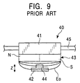
- Fig. 9 is a top plan view showing a conventional magnetic displacement detecting device 40.
- the magnetic displacement detecting device 40 has a detection member 41, a fixed member 42, a magnet 43, and a Hall element 44 serving as a magnetic detecting means.
- the detection member 41 is supported by a rod-shaped guiding member 45, and the detection member 41 linearly moves along the guiding member 45.
- the detection member 41 is provided with the magnet 43 having a hexahedron shape, which has been magnetized so that one end in a traveling direction of the detection member 41 carries the north pole, while the other end carries the south pole.
- the fixed member 42 is secured to a surface of a case (not shown) that opposes the magnet 43.
- the Hall element 44 is provided on surface of the fixed member 42 that opposes the magnet 43. The Hall element 44 detects an intensity of a component in a direction of z of a magnetic force emitted from the magnet 43.
- a torque of a rotator that rotates together with the steering wheel is converted into a linear moving force of the detection member 41.
- the magnet 43 moves together with the detection member 41, opposing the Hall element 44, and a changing rate in the z-direction component of a magnetic field emitted from the magnet 43 at this time is detected through the Hall element 44, thereby allowing a rotational angle of the steering wheel to be known.
- the Hall element 44 detects the intensity of a magnetic field in the z-direction, i.e., a direction orthogonal to a traveling direction of the detection member 41. Based on a changing rate in detection values of the magnetic field in the z-direction, a travel amount of the detection member 41 is recognized.
- the surface of the conventional magnet 43 that opposes the Hall element 44 is flat in the traveling direction. Therefore, a changing rate in the intensity of the magnetic field in the z-direction with respect to a traveling distance is relatively large in the vicinity of both ends in the traveling directions of the magnet 43. In contrast, at a central portion of the magnet 43 in the traveling direction, an area wherein a magnetic force line E0 is substantially flat in the traveling direction expands, and a changing rate in the intensity of the magnetic field in the z-direction with respect to the traveling distance of the magnet 43 becomes extremely small.
- the detection member 41 is moved by the rotator that rotates together with the steering wheel.
- Another rotation detecting means is provided that detects the rotational angle of the rotator with a higher resolution than that of the Hall element 44. In a range wherein the Hall element 44 moves from the center of the magnet 43 to a front or rear end thereof, rough detection of ⁇ 720 degrees of the rotator is performed. During the rough detection, more accurate rotational angle of the rotator is detected by the foregoing rotation detecting means. At this time, a further accurate angle is recognized by the rotation detecting means, by using a detection angle based on a detection value supplied from the Hall element 44.
- the present invention has been made with a view toward solving the problem described above, and it is an object of the present invention to provide a magnetic displacement detecting device for detecting a relative travel amount as linearly as possible by a magnetic detecting means in a case where a detection member having a magnet and a magnetic detecting means relatively move.
- a magnetic displacement detecting device having a detection member that linearly moves and a fixed member provided such that it opposes the detection member, one of the detection member or the fixed member being provided with a magnet having a north pole and a south pole in a traveling direction of the detection member, while the other being provided with a magnetic detecting means, and a magnetic force emitted from the magnet being detected by the magnetic detecting means thereby to detect a movement of the detection member, wherein a distance between the magnet and the magnetic detecting means is the smallest in the vicinity of a center of the magnet and increases toward ends of the magnet.
- Shaping the magnet so that it bulges at its center toward the magnetic detecting means causes a changing rate of a magnetic field in a direction orthogonal to a traveling direction of the magnet to be linear or nearly linear over a longitudinal full length of the magnet in the traveling direction.
- the relative travel distances of the detection member and the magnetic detecting device can be detected with higher accuracy by making use of a changing rate in the magnetic field.
- a surface of the magnet that opposes the magnetic detecting means has a radius shape, including a convex surface in addition to a precise radius shape.
- the surface of the magnet that opposes the magnetic detecting means is trapezoidal.
- the detection member is provided with a rotator, and the detection member linearly is operated by a rotational operation of the rotator, and further provided with an additional detecting means for detecting a rotational angle of the rotator with a higher resolution than that of a detection output obtained by the magnet and the magnetic detecting means together.
- a detailed rotational angle of the rotator is determined from a detection output from the additional detecting means.
- highly accurate positional detection can be achieved by the detection member and the magnetic detecting means. This prevents variations in a reference value for determining a more detailed rotational angle, permitting highly accurate detection of a rotational angle of the rotator.
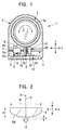
- Fig. 1 is a top plan view showing an internal structure of an angle sensor in which a magnetic displacement detecting device in accordance with the present invention has been installed
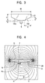
- Fig. 2 is a top plan view showing a shape of a magnet used in the magnetic displacement detecting device in accordance with the present invention
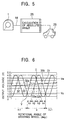
- Fig. 3 is a top plan view showing an example of a modified shape of the magnet
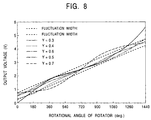
- Fig. 4 is a schematic diagram virtually showing magnetic force lines emitted from the magnet shown in Fig. 2.
- the following will describe an angle sensor capable of detecting a steering angle of an automotive steering wheel with high accuracy.
- An angle sensor 1 shown in Fig. 1 includes a magnetic displacement detecting device 10 housed in a case 2 composed of a synthetic resin material, such as a plastic material.
- the magnetic displacement detecting device 10 has a detection member 4, a magnet 5, a Hall element or a magnetic detecting means 6, and a fixed member 7.
- the magnetic displacement detecting device 10 is further provided with a rotator 3. A rotational operation of the rotator 3 is converted into a linear operation of the detection member 4, and a displacement of the linear operation at that time is detected by the Hall element 6.
- the rotator 3 which is cylindrical, is formed of a synthetic resin material or the like, and rotatably supported with respect to the case 2.
- a plurality of helical gears 3a are formed over an entire peripheral surface of the rotator 3.
- the rotator 3 is further provided with a discoid reduction gear 8 made of a synthetic resin material.
- the reduction gear 8 has a D-shaped through hole (not shown) at a central portion of the discoid body, and is provided with a plurality of helical gears 8a formed on an entire peripheral surface.
- the helical gears 8a mesh with the helical gears 3a.
- a rod-shaped rotating shaft 9 is rotatably installed to the reduction gear 8.
- a section of a portion of the rotating shaft 9 on which the reduction gear 8 is mounted is D-shaped.
- the D-shaped portion of the reduction gear 8 is fitted with the D-shaped portion of the rotating shaft 9, and fixed in the vicinity of the center of the rotating shaft 9.
- the rotating shaft 9 is formed of a metal material, such as brass or aluminum, has a spiral thread groove 9a formed from a central portion to one end, and is rotatably supported with respect to the case 2.
- the rotating shaft 9 is provided with the detection member 4.
- the detection member 4 has a through hole drilled from one end surface to the other end surface in the traveling direction.
- the through hole has, on its inner peripheral surface, a thread (not shown) that engages the thread groove 9a formed in the rotating shaft 9.
- the magnet 5 is mounted on a bottom surface of the detection member 4 by insert molding or the like.
- the detection member 4 is guided in the case 2 such that it linearly moves in the x-direction. Hence, when the rotator 3 rotates and the reduction gear 8 and the rotating shaft 9 rotate, the detection member 4 and the magnet 5 reciprocate in a direction indicated by an arrow B or in the x-direction.
- the magnet 5 is formed of a magnetic material, such as ferrite, and shaped so that it is lengthy in traveling directions. One end of the magnet 5 in the traveling directions has been magnetized to a north pole 5a, while the other end thereof has been magnetized to a south pole 5b. In other words, the magnet 5 has been magnetized to be polarized so that one end thereof in the x-direction carries the north pole, while the other end thereof carries the south pole.
- the fixed member 7 is provided, opposing the magnet 5, and the fixed member 7 is secured to the case 2.
- the fixed member 7 is formed of a plane insulating board, a desired conductive pattern being formed on the insulating board. Electric components, including resistors and capacitors (not shown), that constitute an electric circuit are mounted on the conductive pattern.
- the Hall element 6 is provided on the fixed member 7 at a side opposing the magnet 5.
- the Hall element 6 which is a magneto-electric element for converting magnetic energy into electric energy, is retained by a holder 16 supported by the fixed member 7.
- the Hall element 6 detects a magnetic field intensity of a z-axis component of a magnetic field obtained from the magnet 5.
- the magnet 5 is shaped so that a section thereof cut by an x-z plane or a plane observed from a side is radius-shaped.
- the section is radius-shaped or convex on one lengthwise side of the rectangular shape.
- the radius shape may have a precise arc surface or a convex surface approximating to an arc surface.
- W a width of the magnet 5 in the x-direction
- H a thickness of the curved surface
- R a diameter of the curved surface
- a distance (L) between the magnet 5 and the Hall element 6 serving as the magnetic detecting means is fixed to 0.8 mm.
- the magnet 5 emitting virtual lines of magnetic force E shown in Fig. 4 is obtained. More specifically, the magnet 5 radiates lines of magnetic force from the north pole to the south pole. As illustrated, the lines of magnetic force E radiated from the magnet 5 having the shape shown in Fig. 4 are emitted not only from both ends of the magnet 5 but from the curved surface portion 5A of the magnet 5 also.
- a point P on the lines of magnetic force E in the vicinity of the center of the magnet 5 if a magnitude and a direction of a magnetic force in a tangential direction of the lines of magnetic forces E are represented by a magnetic field H, then a vector component of the magnetic field H in the z-direction can be represented by a magnetic field Hz.
- a magnetic force having a sufficiently large vector component can be output to the Hall element 6 or in the z-direction.
- the vector components in the z-direction of the magnetic forces which have hardly been emitted from the conventional magnet having the hexahedral shape, can be emitted in the vicinity of the center of the magnet 5. Furthermore, a density of lines of magnetic force is lower than that in the conventional magnet having the hexahedral shape in which the lines of magnetic force becomes denser toward ends of the magnet 5. Hence, a sudden changing rate in an output of the Hall element 6 no longer occurs.
- a changing rate of the vector component Hz of a magnetic field in the z-direction with respect to a scanning distance or a moving distance can be made more linear than in the past when the Hall element 6 is scanned from one end to the other end of the magnet 5.
- Fig. 3 shows a modification example of the shape of the magnet 5.
- a section of a magnet 15 cut by a plane of an x-z axis of the magnet may be trapezoidal as illustrated.
- the magnet 15 has slant or tapered surfaces 15c and 15c formed by equally cutting off both corners of the hexahedral magnet that face the Hall element 6 as illustrated.
- W a width of the magnet 15 in the x-direction
- H a z-direction
- X a cutoff length in an x-axis direction of the slant surfaces 15c
- Y a cutoff length in the z-direction of the slant surfaces 15c
- Fig. 7 shows a changing rate in detected intensity of the vector component Hz, with the Hall element 6 in relation to a rotational angle of the rotator 3 when the opposing surface has the radius shape as shown in Fig. 2.
- a distance between the magnetic detecting means and a distal end of the magnet that is adjacent the magnetic detecting means is fixed to 0.8 mm (the same applies also to Fig. 8).
- the predetermined fluctuation range means a permissible range in achieving commercialization, namely, a range of ⁇ 5% in relation to output changes from 0 to 1440 degrees in Fig. 7 according to this embodiment.
- the fluctuation significantly deviates from the above fluctuation range if R is 15mm, which is smaller than the above predetermined range, or 55 mm, which is larger than the above predetermined range.
- a preferable value of R is determined.
- the value of R ranges from 20 to 50 mm, and the thickness H in this case ranges from 1 to 5 mm.
- Fig. 8 shows a changing rate in detected intensity of the vector component Hz, with the Hall element 6 in relation to a rotational angle of the rotator 3 when the opposing surface of the magnet is trapezoidal as shown in Fig. 3.
- Y is in a range of 0.4 to 0.6 mm, fluctuation in intensity can be controlled approximately to a predetermined fluctuation range (the range of ⁇ 5% in relation to output changes from 0 to 1440 degrees as set forth above) without great deviation from the predetermined range when the rotator is at any angle from 0 to 1440 degrees.
- Y is smaller than 0.4 mm or larger than 0.6 mm, then an output voltage significantly deviates from the fluctuation range.
- a preferable value of Y is determined as described above, and a conclusion is reached that the value of Y preferably ranges from 0.4 to 0.6 mm. If the value of Y is fixed, while the value of X is changed, it is concluded that X preferably ranges from 4.25 to 4.75 mm. Regardless of whether the value of Y or X is fixed, it is preferable to set W to 10 to 20 mm, and H to 1 to 5 mm.
- the angle sensor 1 is provided with another magnetic rotation detecting device 20.
- the rotation detecting device 20 is formed by a second magnet 21, a second Hall element 22, and a third Hall element 23.
- the second magnet 21, which is annular, is formed of a magnetic material, such as ferrite, as in the case of the foregoing magnet 5 or 15.
- An outer peripheral surface of the second magnet 21 has been magnetized such that a north pole and a south pole pass by the Hall element 22 once or twice while the magnet 21 rotates once.
- the second magnet 21 is secured to the rotating shaft 9 in the vicinity of the reduction gear 8.
- the arrangement described above enables the magnetic displacement detecting device 10 to detect an approximate rotational angle of the rotator 3, and the rotation detecting device 20 to detect a more accurate rotational angle of the rotator 3.
- the Hall element 6, the second Hall element 22, and the third Hall element 23 are mounted on the fixed member 7 provided in the case 2.
- the third Hall element 23 is installed to the second magnet 21 so that it is positioned at an angle of 90 degrees relative to the second Hall element 22.
- the reduction gear 8 is fitted to the rotating shaft 9, and the annular second magnet 21 is also fitted thereto.
- the detection member 4 is screwed onto the rotating shaft 9 on a side opposite from the side where the second magnet 21 of the reduction gear 8 is installed, and the detection member 4 is supported by the rotating shaft 9 so that the magnet 5 is positioned at a central portion of the thread groove 9a.
- the rotating shaft 9 is rotatably supported in the case 2.
- the rotator 3 is placed in the case 2 in such a manner that the helical gears 3a of the rotator 3 mesh with the helical gears 8a of the reduction gear 8, and the case 2 is covered by a covering member (not shown).
- the third Hall element 23 may alternatively be provided on the covering member.
- the rotator 3 is adapted to rotate twice clockwise and counterclockwise, respectively, from a neutral state.
- the number of rotations is not limited to two.
- the reduction gear 8 and the rotating shaft 9 rotate together.
- the reduction gear 8 rotates four times while the rotator 3 rotates once.
- the rotational operation of the rotator 3 causes the reduction gear 8 to rotate in one direction, and the rotating shaft 9 rotates in one direction together with the reduction gear 8.
- the rotating shaft 9 rotates with the thread groove 9a meshed with a thread (not shown) of the detection member 4, thereby converting the rotational motion of the rotating shaft 9 into a linear motion of the detection member 4.
- the detection member 4 moves, together with the magnet 5, along the rotating shaft 9 in a direction indicated by the arrow B and reaches one end of the thread groove 9a.
- the reduction gear 8 and the rotating shaft 9 rotate in the opposite direction from the foregoing direction. This causes the detection member 4 to move in the opposite direction from the foregoing direction, and reach a center of the thread groove 9a.
- the detection member 4 reaches the other end of the thread groove 9a.
- the magnet 5 and the Hall element 6 constitute a first detecting means.
- the second magnet 21, the second Hall element 22, and the third Hall element 23 constitute a second detecting means and a third detecting means.
- the Hall element 6 detects a movement of the magnet 5 and generates a first detection signal 31 that gradually increases or decreases.
- the first detection signal 31 linearly changes from 0.5 bolts (V) to 4.5 V while the steering wheel rotates four times. This makes it possible to detect a rough or approximate rotational angle of the steering wheel, which rotates with the rotator 3 as one piece, from a neutral position and a rotational direction thereof.
- a microcomputer 25 shown in Fig. 5 serves as a means for calculating a rotational angle of the steering wheel.
- the angle sensor 1 is mounted on an automobile, and connected to a control device 26 of an automotive suspension, automatic transmission, etc.
- the microcomputer 25 receives first, second, and third detection signals 31, 32, and 33 as input signals via a cable 18, and superimpose these signals to detect an approximate rotational angle from the neutral position and a rotational direction of the steering wheel by referring to the first detection signal 31, and to detect a detailed or accurate rotational angle of the steering wheel by referring to the second detection signal 32 and the third detection signal 33.
- rough detection of the rotational angle is performed mainly by determining whether the rotational angle of the steering wheel falls within an angle range of an n-th zone ("n" is a positive number), an (n-1)th zone, or an (n+1)th zone shown in Fig. 6. Further, as shown in Fig. 6, the rotating shaft 9 rotates four times while the steering wheel rotates once; therefore, four sine curves are generated in one zone.
- Vz-Vw range the other signal falls within the range defined by Vz and Vw (hereinafter referred to as "Vz-Vw range").
- the other signal is processed as the signal for detecting an accurate rotational angle of the steering wheel.
- the microcomputer 25 determines whether the other signal that lies in the Vz-Vw range is the second detection signal 32 or the third detection signal 33, and also determines whether the signal that is out of the Vz-Vw range is larger than the voltage value Vw or smaller than the voltage value Vz thereby to determine which one of zones h1, h2, h3, and h4 the other signal that lies in the Vz-Vw range belongs to.
- slope sections 32a, 33a, 32b, and 33b indicated by thick lines in the range "n" of Fig. 6 are obtained.
- the microcomputer 25 uses the slope sections 32a, 33a, 32b, and 33b of the second and third detection signals 32 and 33 to detect the accurate rotational angle of the steering wheel.
- the first detection signal 31 can be complemented all over the area (-720° to 720° in this case) owing to the absence of a signal-free area, because the second and third detection signals 32 and 33 share the same cycle, and a phase of the second detection signal 32 and a phase of the third detection signal 33 are set so that they are shifted by a 1/4 cycle.
- an accurate rotational angle can be detected by making use of the slope sections 32a, 33a, 32b, and 33b that always exhibit large and linear changes in output voltage in relation to changes in the angle of the steering wheel.
- the rotational angle of the steering wheel can be detected over the entire area with high accuracy in a realtime mode.
- the rotational angle and direction of the steering wheel that have been detected as described above are sent from the microcomputer 25 to the control device 26 of the automobile so as to carry out detailed control of the automotive suspension, automatic transmission, etc.
- the present invention is not limited to the embodiment set forth above.
- the magnet 5 may have a stepped shape or a hill-like shape. Not only the surface of the magnet that opposes the Hall element 6, but a shape of an opposite surface thereof may be modified as necessary as long as linear outputs are obtained from the Hall element 6.
- a magnet having a shape that causes a density of magnetic fluxes to change linearly is employed. This makes it possible to obtain linear outputs at any rotational angles when a rotator is rotated, so that obtained output values can be directly processed, permitting realtime processing.
- the magnetic displacement detecting device in accordance with the present invention may be attached to a steering shaft of an automobile to accurately detect angles of clockwise and counterclockwise rotations from a neutral position.
- an attitude of the automobile can be controlled by controlling tightness of a suspension, a transmission gear ratio of an automatic transmission, etc.
Landscapes
- Physics & Mathematics (AREA)
- Engineering & Computer Science (AREA)
- Remote Sensing (AREA)
- General Physics & Mathematics (AREA)
- Life Sciences & Earth Sciences (AREA)
- Electromagnetism (AREA)
- Environmental & Geological Engineering (AREA)
- Geology (AREA)
- General Life Sciences & Earth Sciences (AREA)
- Geophysics (AREA)
- Transmission And Conversion Of Sensor Element Output (AREA)
- Measurement Of Length, Angles, Or The Like Using Electric Or Magnetic Means (AREA)
Abstract
Description
Claims (6)
- A magnetic displacement detecting device comprising a detection member that linearly moves and a fixed member provided such that it opposes the detection member, one of the detection member or the fixed member being provided with a magnet having a north pole and a south pole in a traveling direction of the detection member, while the other being provided with magnetic detecting means, and a magnetic force emitted from the magnet being detected by the magnetic detecting means thereby to detect a movement of the detection member,
wherein a distance between the magnet and the magnetic detecting means is the smallest in the vicinity of a center of the magnet and larger at end portions of the magnet than in the vicinity of the center. - A magnetic displacement detecting device according to Claim 1, wherein a surface of the magnet that opposes the magnetic detecting means has a radius shape.
- A magnetic displacement detecting device according to Claim1 or 2, wherein, if a width of the magnet in a direction in which the magnet or the magnetic detecting means moves is denoted by W, and a thickness of the magnet in a direction in which the magnet and the magnetic detecting means face each other is denoted by H, then a shape proportion of the magnet has a relationship represented as W = 10 to 20, H = 1 to 5, and R = 20 to 50.
- A magnetic displacement detecting device according to Claim 1, wherein the surface of the magnet that opposes the magnetic detecting means is trapezoidal.
- A magnetic displacement detecting device according to Claim 4, wherein, if a width of the magnet in a direction in which the magnet or the magnetic detecting means moves is denoted by W, a thickness of the magnet in a direction in which the magnet and the magnetic detecting means face each other is denoted by H, a length of cutoffs in the H-direction of tapers at both ends of the trapezoid is denoted by Y, and a length of cutoffs in the W-direction of the tapers is denoted by X, then a shape proportion of the magnet has a relationship represented by W = 10 to 20, H = 1 to 5, X = 4.25 to 4.75, and Y = 0.4 to 0.6.
- A magnetic displacement detecting device according to any preceding claim, wherein the detection member is provided with a rotator, the detection member linearly operating by a rotational operation of the rotator, and further provided with an additional detecting means for detecting a rotational angle of the rotator with a higher resolution than that of a detection output obtained by the magnet and the magnetic detecting means together.
Applications Claiming Priority (2)
| Application Number | Priority Date | Filing Date | Title |
|---|---|---|---|
| JP22518599A JP3597733B2 (en) | 1999-08-09 | 1999-08-09 | Magnetic displacement detector |
| JP22518599 | 1999-08-09 |
Publications (3)
| Publication Number | Publication Date |
|---|---|
| EP1076225A2 true EP1076225A2 (en) | 2001-02-14 |
| EP1076225A3 EP1076225A3 (en) | 2004-04-21 |
| EP1076225B1 EP1076225B1 (en) | 2006-06-07 |
Family
ID=16825305
Family Applications (1)
| Application Number | Title | Priority Date | Filing Date |
|---|---|---|---|
| EP00306205A Expired - Lifetime EP1076225B1 (en) | 1999-08-09 | 2000-07-21 | Magnetic displacement detector |
Country Status (4)
| Country | Link |
|---|---|
| US (1) | US6496003B1 (en) |
| EP (1) | EP1076225B1 (en) |
| JP (1) | JP3597733B2 (en) |
| DE (1) | DE60028472T2 (en) |
Cited By (9)
| Publication number | Priority date | Publication date | Assignee | Title |
|---|---|---|---|---|
| WO2005064281A1 (en) * | 2003-12-30 | 2005-07-14 | Nct Engineering Gmbh | Position sensor |
| WO2005088267A1 (en) * | 2004-03-10 | 2005-09-22 | Robert Bosch Gmbh | Connector element |
| EP1832783A1 (en) * | 2006-03-02 | 2007-09-12 | GETRAG Getriebe- und Zahnradfabrik Hermann Hagenmeyer GmbH & Cie KG | Sensor assembly and switching assembly |
| DE102007009389A1 (en) | 2007-02-20 | 2008-08-21 | Bizerba Gmbh & Co. Kg | Force measuring device and method for signal evaluation |
| US7598862B2 (en) | 2006-12-16 | 2009-10-06 | Roc2Loc, Inc. | Methods and apparatus for security device coupling |
| US7663483B2 (en) | 2006-12-16 | 2010-02-16 | Roc2Loc, Inc. | Methods and apparatus for security device portal sensing |
| US7667600B2 (en) | 2006-12-16 | 2010-02-23 | Roc2Loc, Inc. | Methods and apparatus for security device removal detection |
| WO2010141420A2 (en) | 2009-06-04 | 2010-12-09 | Key Safety Systems, Inc. | Temperature tolerant magnetic linear displacement sensor |
| EP2365290A3 (en) * | 2010-01-18 | 2014-02-26 | Bourns, Inc. | High resolution non-contacting multi-turn position sensor |
Families Citing this family (30)
| Publication number | Priority date | Publication date | Assignee | Title |
|---|---|---|---|---|
| US9155544B2 (en) | 2002-03-20 | 2015-10-13 | P Tech, Llc | Robotic systems and methods |
| US7497864B2 (en) | 2003-04-30 | 2009-03-03 | Marctec, Llc. | Tissue fastener and methods for using same |
| US20040250934A1 (en) * | 2003-06-11 | 2004-12-16 | Randy Hamdan | Tires with magnetic strips |
| US7088095B1 (en) | 2004-02-04 | 2006-08-08 | Honeywell International Inc. | Balanced magnetic linear displacement sensor |
| US20050194967A1 (en) * | 2004-03-03 | 2005-09-08 | Arquimedes Godoy | Apparatus for sensing angular positions of an object |
| JP4911889B2 (en) * | 2004-10-14 | 2012-04-04 | ヤマハ発動機株式会社 | Relative position detection device and saddle riding type vehicle |
| DE102004060920B4 (en) * | 2004-12-17 | 2007-03-22 | Woco Industrietechnik Gmbh | Bar magnet for measuring device, measuring device |
| WO2006115129A1 (en) | 2005-04-19 | 2006-11-02 | Matsushita Electric Industrial Co., Ltd. | Position sensor, optical head device, head moving mechanism, information recording/reproducing device and position control system |
| JP5022724B2 (en) * | 2006-03-07 | 2012-09-12 | 株式会社ミツトヨ | Absolute position measuring device |
| US7443160B2 (en) * | 2006-09-28 | 2008-10-28 | Wolf Ronald J | Position sensor |
| EP2088397A4 (en) * | 2006-10-26 | 2011-06-08 | Furukawa Electric Co Ltd | Rotation angle detector |
| JP4832358B2 (en) * | 2007-05-16 | 2011-12-07 | アルプス電気株式会社 | Position detection device |
| JP4853496B2 (en) * | 2007-07-30 | 2012-01-11 | 株式会社デンソー | Position detection sensor |
| JP2009276230A (en) * | 2008-05-15 | 2009-11-26 | Asmo Co Ltd | Stroke sensor, actuator and vehicle headlight device |
| JP4606485B2 (en) * | 2008-09-02 | 2011-01-05 | アルプス電気株式会社 | Movement detection device using magnets |
| JP5036669B2 (en) * | 2008-09-12 | 2012-09-26 | 三菱電機株式会社 | Position detection device for moving parts, 2-DOF actuator |
| US8004277B2 (en) * | 2008-12-30 | 2011-08-23 | Honeywell International Inc. | Rotary position sensing apparatus |
| KR101047304B1 (en) * | 2010-08-26 | 2011-07-07 | 주식회사 유니크 | Magnet and position sensor |
| US9080895B2 (en) * | 2011-05-25 | 2015-07-14 | Sensata Technologies, Inc. | Magnetic position sensor assembly for measurement of rotational angular position of a rotating structure |
| JP6109834B2 (en) * | 2011-10-07 | 2017-04-05 | ノボ・ノルデイスク・エー/エス | System for determining the position of an element based on a three-axis magnetic sensor |
| US9448087B2 (en) * | 2011-10-10 | 2016-09-20 | Methode Electronics, Inc. | Contactless magnetic linear position sensor |
| EP2981310B1 (en) | 2013-04-05 | 2017-07-12 | Novo Nordisk A/S | Dose logging device for a drug delivery device |
| JP6262620B2 (en) * | 2014-08-29 | 2018-01-17 | 株式会社デンソー | Position detection device |
| JP6476700B2 (en) * | 2014-09-30 | 2019-03-06 | 日立金属株式会社 | Permanent magnet, position sensor, permanent magnet manufacturing method and magnetizing apparatus |
| US10058393B2 (en) | 2015-10-21 | 2018-08-28 | P Tech, Llc | Systems and methods for navigation and visualization |
| JP6492193B2 (en) * | 2015-10-28 | 2019-03-27 | アルプスアルパイン株式会社 | Position detection device |
| US11874140B2 (en) | 2016-02-17 | 2024-01-16 | Infineon Technologies Ag | Tapered magnet |
| US20190063951A1 (en) * | 2017-08-29 | 2019-02-28 | Littelfuse, Inc. | Sensitivity enhanced gear absolute position sensor |
| GB2592611B (en) * | 2020-03-03 | 2024-11-27 | Zf Automotive Uk Ltd | A magnetic encoder |
| WO2023058356A1 (en) * | 2021-10-04 | 2023-04-13 | 株式会社村田製作所 | Position detecting device |
Family Cites Families (13)
| Publication number | Priority date | Publication date | Assignee | Title |
|---|---|---|---|---|
| DE1303818C2 (en) * | 1966-09-22 | 1973-08-02 | Siemens Ag | ANALOG HYSTERESIS-FREE TRANSDUCER WITH HALL GENERATOR |
| US4107604A (en) * | 1976-12-01 | 1978-08-15 | Compunetics, Incorporated | Hall effect displacement transducer using a bar magnet parallel to the plane of the Hall device |
| JPS54103372A (en) * | 1978-01-31 | 1979-08-14 | Matsushita Electric Works Ltd | Magnetic sensor |
| JPS61134601A (en) * | 1984-12-06 | 1986-06-21 | Kokusan Denki Co Ltd | Magnetic type displacement sensor |
| JPS62229002A (en) | 1986-03-31 | 1987-10-07 | Matsushita Electric Ind Co Ltd | Position detector |
| CH674058A5 (en) * | 1986-10-22 | 1990-04-30 | Festo Kg | |
| JPH04166906A (en) * | 1990-10-31 | 1992-06-12 | Sony Corp | Original position detecting device for lens barrel |
| US5159268A (en) * | 1991-02-21 | 1992-10-27 | Honeywell Inc. | Rotational position sensor with a Hall effect device and shaped magnet |
| US5493216A (en) * | 1993-09-08 | 1996-02-20 | Asa Electronic Industry Co., Ltd. | Magnetic position detector |
| JP3395402B2 (en) * | 1994-10-14 | 2003-04-14 | 住友電気工業株式会社 | Travel detector |
| US5929631A (en) * | 1997-07-02 | 1999-07-27 | Ford Global Technologies, Inc. | Method of position sensing utilizing giant magneto resistance elements and solid state switch array |
| GB9720911D0 (en) * | 1997-10-03 | 1997-12-03 | Britax Rainsfords Pty Ltd | Hall effect sensor system |
| US6218828B1 (en) * | 1998-12-21 | 2001-04-17 | Caterpillar Inc. | Sensing system for determining an articulation angle between two elements |
-
1999
- 1999-08-09 JP JP22518599A patent/JP3597733B2/en not_active Expired - Lifetime
-
2000
- 2000-07-21 EP EP00306205A patent/EP1076225B1/en not_active Expired - Lifetime
- 2000-07-21 DE DE60028472T patent/DE60028472T2/en not_active Expired - Lifetime
- 2000-08-09 US US09/635,347 patent/US6496003B1/en not_active Expired - Fee Related
Cited By (15)
| Publication number | Priority date | Publication date | Assignee | Title |
|---|---|---|---|---|
| WO2005064281A1 (en) * | 2003-12-30 | 2005-07-14 | Nct Engineering Gmbh | Position sensor |
| US7243557B2 (en) | 2003-12-30 | 2007-07-17 | Nctengineering Gmbh | Torque sensor |
| US7685891B2 (en) | 2003-12-30 | 2010-03-30 | Nct Engineering Gmbh | Magnetic principle based torque sensor |
| WO2005088267A1 (en) * | 2004-03-10 | 2005-09-22 | Robert Bosch Gmbh | Connector element |
| EP1832783A1 (en) * | 2006-03-02 | 2007-09-12 | GETRAG Getriebe- und Zahnradfabrik Hermann Hagenmeyer GmbH & Cie KG | Sensor assembly and switching assembly |
| US7663483B2 (en) | 2006-12-16 | 2010-02-16 | Roc2Loc, Inc. | Methods and apparatus for security device portal sensing |
| US7598862B2 (en) | 2006-12-16 | 2009-10-06 | Roc2Loc, Inc. | Methods and apparatus for security device coupling |
| US7667600B2 (en) | 2006-12-16 | 2010-02-23 | Roc2Loc, Inc. | Methods and apparatus for security device removal detection |
| DE102007009389A1 (en) | 2007-02-20 | 2008-08-21 | Bizerba Gmbh & Co. Kg | Force measuring device and method for signal evaluation |
| WO2010141420A2 (en) | 2009-06-04 | 2010-12-09 | Key Safety Systems, Inc. | Temperature tolerant magnetic linear displacement sensor |
| EP2438391A4 (en) * | 2009-06-04 | 2015-01-21 | Key Safety Systems Inc | Temperature tolerant magnetic linear displacement sensor |
| EP3171126A1 (en) * | 2009-06-04 | 2017-05-24 | Littelfuse, Inc. | Temperature tolerant magnetic linear displacement sensor |
| EP2365290A3 (en) * | 2010-01-18 | 2014-02-26 | Bourns, Inc. | High resolution non-contacting multi-turn position sensor |
| US8947076B2 (en) | 2010-01-18 | 2015-02-03 | Bourns, Inc. | High resolution non-contacting multi-turn position sensor |
| US9518840B2 (en) | 2010-01-18 | 2016-12-13 | Bourns, Inc. | High resolution non-contacting multi-turn position sensor |
Also Published As
| Publication number | Publication date |
|---|---|
| US6496003B1 (en) | 2002-12-17 |
| EP1076225B1 (en) | 2006-06-07 |
| JP3597733B2 (en) | 2004-12-08 |
| JP2001050703A (en) | 2001-02-23 |
| DE60028472D1 (en) | 2006-07-20 |
| DE60028472T2 (en) | 2007-01-04 |
| EP1076225A3 (en) | 2004-04-21 |
Similar Documents
| Publication | Publication Date | Title |
|---|---|---|
| EP1076225B1 (en) | Magnetic displacement detector | |
| US6630823B2 (en) | Rotation angle detector | |
| US5955881A (en) | Linkage position sensor having a magnet with two ramped sections for providing variable magnetic field | |
| US6909282B2 (en) | Rotation angle detector | |
| US6400143B1 (en) | Digital sensor of relative position | |
| KR101721087B1 (en) | Multi-periodic absolute position sensor | |
| US7994742B2 (en) | Position measurement using magnetic fields | |
| KR101410196B1 (en) | Bidirectional magnetic position sensor having field rotation | |
| CN105992933B (en) | Sensor module for the rotation angle for obtaining the rotating member in vehicle | |
| US6229299B1 (en) | System and method for computing the angular velocity and direction of a rotational body | |
| EP2103909A1 (en) | Rotation angle detection device | |
| US6218829B1 (en) | Linear drive having a device for registering the displacement travel and/or position | |
| EP1108987B1 (en) | Rotational angle detecting device | |
| US20030088989A1 (en) | Rotational angle detector and rotational angle detecting method | |
| US12111220B2 (en) | Sensor assembly for sensing a steering torque and an absolute angular position, and sensor device having said sensor assembly | |
| US20070241742A1 (en) | Rotation angle detection apparatus | |
| JPH11248486A (en) | Pickup of rotating shaft position and speed | |
| US11150109B2 (en) | Displacement detecting device and continuously variable transmission device | |
| EP1845343B1 (en) | Rotational angle detector | |
| EP2080993A1 (en) | Rotation angle determining apparatus | |
| US7463023B1 (en) | Non-contacting rotary and linear travel sensor | |
| US7211999B2 (en) | Rotation angle detector | |
| US6501263B1 (en) | Rotary position sensor | |
| JP2010181310A (en) | Rotational angle/torque detection device | |
| US20030137291A1 (en) | Angle sensor with a magnetoelectrical converter element |
Legal Events
| Date | Code | Title | Description |
|---|---|---|---|
| PUAI | Public reference made under article 153(3) epc to a published international application that has entered the european phase |
Free format text: ORIGINAL CODE: 0009012 |
|
| AK | Designated contracting states |
Kind code of ref document: A2 Designated state(s): AT BE CH CY DE DK ES FI FR GB GR IE IT LI LU MC NL PT SE |
|
| AX | Request for extension of the european patent |
Free format text: AL;LT;LV;MK;RO;SI |
|
| PUAL | Search report despatched |
Free format text: ORIGINAL CODE: 0009013 |
|
| AK | Designated contracting states |
Kind code of ref document: A3 Designated state(s): AT BE CH CY DE DK ES FI FR GB GR IE IT LI LU MC NL PT SE |
|
| AX | Request for extension of the european patent |
Extension state: AL LT LV MK RO SI |
|
| 17P | Request for examination filed |
Effective date: 20040605 |
|
| AKX | Designation fees paid |
Designated state(s): DE FR GB SE |
|
| 17Q | First examination report despatched |
Effective date: 20050217 |
|
| GRAP | Despatch of communication of intention to grant a patent |
Free format text: ORIGINAL CODE: EPIDOSNIGR1 |
|
| GRAS | Grant fee paid |
Free format text: ORIGINAL CODE: EPIDOSNIGR3 |
|
| GRAA | (expected) grant |
Free format text: ORIGINAL CODE: 0009210 |
|
| AK | Designated contracting states |
Kind code of ref document: B1 Designated state(s): DE FR GB SE |
|
| REG | Reference to a national code |
Ref country code: GB Ref legal event code: FG4D |
|
| REF | Corresponds to: |
Ref document number: 60028472 Country of ref document: DE Date of ref document: 20060720 Kind code of ref document: P |
|
| REG | Reference to a national code |
Ref country code: SE Ref legal event code: TRGR |
|
| ET | Fr: translation filed | ||
| PLBE | No opposition filed within time limit |
Free format text: ORIGINAL CODE: 0009261 |
|
| STAA | Information on the status of an ep patent application or granted ep patent |
Free format text: STATUS: NO OPPOSITION FILED WITHIN TIME LIMIT |
|
| 26N | No opposition filed |
Effective date: 20070308 |
|
| EUG | Se: european patent has lapsed | ||
| PG25 | Lapsed in a contracting state [announced via postgrant information from national office to epo] |
Ref country code: SE Free format text: LAPSE BECAUSE OF NON-PAYMENT OF DUE FEES Effective date: 20070722 |
|
| REG | Reference to a national code |
Ref country code: FR Ref legal event code: ST Effective date: 20080331 |
|
| PGFP | Annual fee paid to national office [announced via postgrant information from national office to epo] |
Ref country code: SE Payment date: 20060724 Year of fee payment: 7 |
|
| PG25 | Lapsed in a contracting state [announced via postgrant information from national office to epo] |
Ref country code: FR Free format text: LAPSE BECAUSE OF NON-PAYMENT OF DUE FEES Effective date: 20070731 |
|
| PG25 | Lapsed in a contracting state [announced via postgrant information from national office to epo] |
Ref country code: FR Free format text: LAPSE BECAUSE OF NON-PAYMENT OF DUE FEES Effective date: 20060731 |
|
| PGFP | Annual fee paid to national office [announced via postgrant information from national office to epo] |
Ref country code: GB Payment date: 20120625 Year of fee payment: 13 |
|
| GBPC | Gb: european patent ceased through non-payment of renewal fee |
Effective date: 20130721 |
|
| PG25 | Lapsed in a contracting state [announced via postgrant information from national office to epo] |
Ref country code: GB Free format text: LAPSE BECAUSE OF NON-PAYMENT OF DUE FEES Effective date: 20130721 |
|
| PGFP | Annual fee paid to national office [announced via postgrant information from national office to epo] |
Ref country code: DE Payment date: 20140731 Year of fee payment: 15 |
|
| REG | Reference to a national code |
Ref country code: DE Ref legal event code: R119 Ref document number: 60028472 Country of ref document: DE |
|
| PG25 | Lapsed in a contracting state [announced via postgrant information from national office to epo] |
Ref country code: DE Free format text: LAPSE BECAUSE OF NON-PAYMENT OF DUE FEES Effective date: 20160202 |