EP1076173A2 - Fuel pump - Google Patents
Fuel pump Download PDFInfo
- Publication number
- EP1076173A2 EP1076173A2 EP00306748A EP00306748A EP1076173A2 EP 1076173 A2 EP1076173 A2 EP 1076173A2 EP 00306748 A EP00306748 A EP 00306748A EP 00306748 A EP00306748 A EP 00306748A EP 1076173 A2 EP1076173 A2 EP 1076173A2
- Authority
- EP
- European Patent Office
- Prior art keywords
- tappet
- fuel pump
- bore
- plunger
- chamber
- Prior art date
- Legal status (The legal status is an assumption and is not a legal conclusion. Google has not performed a legal analysis and makes no representation as to the accuracy of the status listed.)
- Withdrawn
Links
- 239000000446 fuel Substances 0.000 title claims abstract description 70
- 238000005086 pumping Methods 0.000 claims abstract description 50
- 230000009471 action Effects 0.000 claims abstract description 10
- 230000004323 axial length Effects 0.000 claims abstract description 9
- 239000012530 fluid Substances 0.000 claims description 10
- 230000004044 response Effects 0.000 claims description 2
- 239000010687 lubricating oil Substances 0.000 description 8
- 239000003921 oil Substances 0.000 description 8
- 238000000034 method Methods 0.000 description 5
- 238000002347 injection Methods 0.000 description 3
- 239000007924 injection Substances 0.000 description 3
- 230000004048 modification Effects 0.000 description 3
- 238000012986 modification Methods 0.000 description 3
- 238000002485 combustion reaction Methods 0.000 description 2
- 238000004891 communication Methods 0.000 description 2
- 230000001419 dependent effect Effects 0.000 description 2
- 238000005553 drilling Methods 0.000 description 2
- 230000008901 benefit Effects 0.000 description 1
- 230000015572 biosynthetic process Effects 0.000 description 1
- 230000006835 compression Effects 0.000 description 1
- 238000007906 compression Methods 0.000 description 1
- 238000006073 displacement reaction Methods 0.000 description 1
- 210000002969 egg yolk Anatomy 0.000 description 1
- 230000008569 process Effects 0.000 description 1
- 230000009467 reduction Effects 0.000 description 1
- 230000000717 retained effect Effects 0.000 description 1
- 239000000779 smoke Substances 0.000 description 1
- 239000000243 solution Substances 0.000 description 1
Images



Classifications
-
- F—MECHANICAL ENGINEERING; LIGHTING; HEATING; WEAPONS; BLASTING
- F02—COMBUSTION ENGINES; HOT-GAS OR COMBUSTION-PRODUCT ENGINE PLANTS
- F02M—SUPPLYING COMBUSTION ENGINES IN GENERAL WITH COMBUSTIBLE MIXTURES OR CONSTITUENTS THEREOF
- F02M59/00—Pumps specially adapted for fuel-injection and not provided for in groups F02M39/00 -F02M57/00, e.g. rotary cylinder-block type of pumps
- F02M59/02—Pumps specially adapted for fuel-injection and not provided for in groups F02M39/00 -F02M57/00, e.g. rotary cylinder-block type of pumps of reciprocating-piston or reciprocating-cylinder type
- F02M59/10—Pumps specially adapted for fuel-injection and not provided for in groups F02M39/00 -F02M57/00, e.g. rotary cylinder-block type of pumps of reciprocating-piston or reciprocating-cylinder type characterised by the piston-drive
- F02M59/102—Mechanical drive, e.g. tappets or cams
-
- F—MECHANICAL ENGINEERING; LIGHTING; HEATING; WEAPONS; BLASTING
- F02—COMBUSTION ENGINES; HOT-GAS OR COMBUSTION-PRODUCT ENGINE PLANTS
- F02M—SUPPLYING COMBUSTION ENGINES IN GENERAL WITH COMBUSTIBLE MIXTURES OR CONSTITUENTS THEREOF
- F02M59/00—Pumps specially adapted for fuel-injection and not provided for in groups F02M39/00 -F02M57/00, e.g. rotary cylinder-block type of pumps
- F02M59/20—Varying fuel delivery in quantity or timing
- F02M59/30—Varying fuel delivery in quantity or timing with variable-length-stroke pistons
Definitions
- This invention relates to a fuel pump for use in supplying fuel under high pressure for injection into a combustion space of an associated compression ignition internal combustion engine.
- the invention is particularly applicable to unit pump/injectors or to unit pumps, each being intended to deliver fuel to a single associated fuel injector. It will be appreciated, however, that the invention is also applicable to other types of fuel pump, for example in-line pumps.
- the pump of a unit pump/injector typically comprises a pumping plunger reciprocable within a bore under the action of a cam drive arrangement. Motion of the plunger, in use, is dependent upon the cam profile and the speed of operation of the cam drive arrangement. It is desirable to be able to modify the operation of the pump, for example to permit the timing of the delivery of fuel to be controlled, thereby permitting a reduction in the levels of white smoke, particulate emissions and noise produced when the engine is cold, and reducing the risk of miss-fires.
- a fuel pump comprising a pumping plunger reciprocable within a plunger bore under the action of a cam drive arrangement, the cam drive arrangement comprising first and second surfaces defining therebetween a chamber, the volume of which can be controlled to control the spacing of the first and second surfaces, thereby permitting control of the axial length of the cam drive arrangement.
- the pump is of the type in which a filling port is provided, the filling port being obscured, in use, by the pumping plunger
- adjustment of the axial length of the drive arrangement permits the timing at which the filling port is closed by the pumping plunger, and hence the timing of commencement of pressurisation of fuel by the pump, to be controlled.
- the timing of commencement of pressurisation of fuel can be controlled.
- an arrangement is possible in which the timing of fuel delivery can be advanced, for example when the associated engine is cold.
- the first surface is conveniently defined by a tappet member which acts to transmit a force from the cam drive arrangement to the pumping plunger.
- the second surface may be defined by a piston member slidable within a tappet bore formed in the tappet member.
- the fuel pump comprises a spring arrangement arranged to apply a biasing force to the piston member which tends to minimise the volume of the chamber.
- the plunger bore defines a pumping chamber for fuel, reciprocal movement of the pumping plunger within the plunger bore causing fuel pressurisation within the pumping chamber, in use.
- the fuel pump may further comprise a further spring arrangement which is arranged to urge the tappet member in a direction to withdraw the pumping plunger from the plunger bore, thereby tending to maximise the volume of the pumping chamber.
- the cam drive arrangement may include a drive member which carries the piston member, a force from the piston member being transmitted to the pumping plunger through the drive member.
- the drive member and the piston member may be integrally formed.
- the piston member may be secured directly to the pumping plunger.
- the tappet member may be shaped to define, at least in part, a relief passage which communicates with the chamber upon movement of the piston member beyond a predetermined position.
- the tappet member may be provided with a circlip which is engageable with the piston member upon movement of the piston member beyond a predetermined amount.
- the tappet member is slidable within a further bore provided in a housing, the fuel pump preferably comprising means for substantially preventing angular movement of the tappet member within the further bore.
- one of the tappet member and the housing may be provided with a member which extends into a recess provided in the other of the tappet member and the housing so as to substantially prevent angular movement of the tappet member within the further bore.
- the member may take the form of a peg carried by the tappet member, the peg extending through an opening provided in a drive member forming part of the drive arrangement so as to substantially prevent angular movement of the tappet member within the further bore.
- the pump may comprise a yoke secured to the housing, the yoke having at least one projection extending into the further bore provided in the housing, the or each projection cooperating with the tappet member so as to substantially prevent angular movement of the tappet member within the further bore.
- the piston member may include a region of part-spherical form which is cooperable with the tappet bore to permit axial misalignment between the piston member and the tappet member.
- the chamber is arranged to receive fluid through a supply passage, fluid pressure within the chamber applying a force to the first and second surfaces which serves to increase the volume of the chamber.
- the fuel pump may further comprise a temperature sensitive valve arrangement, the pressure of fluid supplied to the chamber being controlled in response to an output from the temperature sensitive valve arrangement.
- an arrangement for use in a fuel pump comprising a pumping plunger which is reciprocable within a plunger bore under the action of a drive arrangement and a tappet member which is slidable within a further bore provided in a housing for transmitting a force from the drive arrangement to the pumping plunger, the arrangement comprising a yoke secured to the housing, the yoke having at least one projection extending into the bore provided in the housing, the or each projection cooperating with the tappet member so as to substantially prevent angular movement of the tappet member within the further bore.
- this aspect of the invention is not limited to use in a fuel pump driven by means of a cam drive arrangement, nor is it limited to use in a fuel pump in which first and second surfaces of the drive arrangement define a chamber, the volume of which can be controlled to control the spacing of the first and second surfaces.
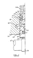
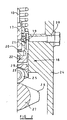
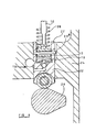
- the fuel pump illustrated in Figures 1, 2 and 3 is intended to form part of a unit pump/injector and comprises a pumping plunger 10 which is reciprocable within a bore 11 formed in a pump body 12.
- the plunger 10 and bore 11 together define a pumping chamber 13 which communicates with an outlet passage 14 and, depending upon the axial position occupied by the pumping plunger 10, with a feed or filling port 15.
- the feed port 15 communicates with a suitable low pressure fuel reservoir 16.
- the plunger 10 is secured to a drive member 17 forming part of a drive arrangement 18.
- the drive member 17 carries a piston member 19, a shim 20 being located between the piston member 19 and the drive member 17 such that the axial position of the piston member 19 relative to the drive member 17 can be set during the assembly process of the drive arrangement 18.
- the piston member is slidable within a bore 21 formed in a tappet 22, the tappet 22 being slidable within a bore 23 formed in a housing member 24.
- the tappet 22 carries a roller 25, the outer periphery of which is engageable with a cam 26 mounted upon a drive shaft 27.
- the bore 21 provided in the tappet 22 defines, with the piston member 19, a chamber 28 of variable volume.
- the tappet 22 is provided with drillings defining a flow passage 29 whereby engine lubricating oil or another fluid can be supplied to the chamber 28.
- a ball valve arrangement 30 is provided to restrict the flow of fluid from the chamber 28 along the passage 29, but to permit fuel flow towards the chamber 28 at a substantially unrestricted rate.
- the ball valve arrangement 30 is conveniently spring-biased closed.
- the flow passage 29 communicates with an annular recess 31 defined between the tappet 22 and the wall of the bore 23, the recess 31 communicating, in turn, with a supply passage 32 which is arranged such that, in use, lubricating oil or another fluid at a desired pressure can be applied thereto.
- a supply passage 32 which is arranged such that, in use, lubricating oil or another fluid at a desired pressure can be applied thereto.
- the tappet 22 is shaped to define a relief passage 33 which communicates with the chamber 28 upon movement of the piston member 19 beyond a predetermined position.
- the relief passage 33 communicates with the interior of the cam housing and is thus under relatively low oil pressure.
- the open end of the bore 21 provided in the tappet 22 is closed by means of a cap 34 which is retained in position using a spring clip 35 or any other suitable technique.
- a spring 36 is engaged between the cap 34 and a spring abutment member 37 carried by the drive member 17 to apply a biasing force to the piston member 19 urging the piston member 19 into engagement with the blind end of the bore 21 formed in the tappet 22.
- the spring 36 therefore urges the piston member 19 towards a position in which the chamber 28 is of minimum volume.
- the cap 34 further engages a return spring 38 which is positioned to urge the tappet 22 in a direction to withdraw the plunger 10 from the bore 11, urging the plunger 10 towards a position in which the pumping chamber 13 is of maximum volume.
- the housing 24 is provided with a screw-threaded pin 39, an end of which projects into the bore 23 and rides within a slot formed in the tappet 22 to hold the tappet 22 against angular movement within the bore 23, but to allow axial movement of the tappet 22 in a substantially unrestricted manner. It will be appreciated that by holding the tappet 22 against angular movement, the roller 25 is held such that its axis of rotation lies substantially parallel to the axis of rotation of the drive shaft 27.
- the chamber 28 In use, with the supply passage 32 being supplied with engine lubricating oil at a relatively low pressure, the chamber 28 is at relatively low pressure and the spring 36 urges the piston member 19 towards the position shown in which the end surface thereof engages the surface defined by the blind end of the bore 21.
- the roller 25 is in engagement with the base of the cam 26, the roller 25 being urged into engagement with the cam 26 by the return spring 38.
- the tappet 22 occupies its outermost position, and likewise the plunger 10 occupies its outermost position. As illustrated in Figure 3, in this position the pumping chamber 13 communicates with the feed port 15, the pumping chamber 13 being charged with fuel to a relatively low pressure.
- Rotation of the drive shaft 27 causes the roller 25 to move into engagement with the cam lobe, causing the tappet 22 to move upwardly in the orientation illustrated in Figures 1 and 2, the movement of the tappet 22 being transmitted directly to the piston member 19, and through the shim 20 to the drive member 17 from where it is transmitted to the pumping plunger 10 urging the pumping plunger 10 in an upwards direction in the orientation illustrated in Figure 3.
- the initial movement of the pumping plunger 10 displaces fuel from the pumping chamber 13 through the feed port 15 to the reservoir 16. Displacement of fuel from the pumping chamber 13 in this manner continues until the pumping plunger 10 has moved by a sufficient distance to close the feed port 15.
- Fuel delivery at high pressure continues until either a spill valve connected to the outlet passage 14 is opened or the plunger 10 reaches an inner position, or more preferably by a spill passage or groove, conveniently of angled or helical form, provided in the plunger aligns with the feed port provided in the housing to allow fuel to escape from the pumping chamber to a low pressure reservoir. Once the plunger reaches an inner position, movement of the plunger 10 to the position illustrated occurs under the action of the return spring 38.
- lubricating oil under relatively high pressure is applied to the supply passage 32.
- Such an application of lubricating oil under pressure permits oil to flow through the passage 29 past the non-return valve 30 to the chamber 28.
- the oil under pressure acts upon the surfaces of the piston member 19 and the blind end of the bore 21 formed in the tappet 22 urging these surfaces away from one another, movement of the piston member 19 relative to the tappet 22 continuing until a position is reached in which the chamber 28 communicates with the relief passage 33.
- the movement of the piston member 19 away from the blind end of the bore 21 formed in the tappet 22 occurs against the action of the spring 36.
- the movement of the piston member 19 is intended to occur when the tappet 22 occupies substantially the position illustrated in Figures 1 and 2 and the movement of the piston member 19 is transmitted to the plunger 10, thereby moving the plunger 10 from its outermost position by a small distance, for example to the position illustrated by a dotted line in Figure 3.
- the inward movement of the tappet 22 causes inward movement of the plunger 10 as described hereinbefore.
- the axial length of the drive arrangement 18 is increased by moving the piston member 19 relative to the tappet 22 as described hereinbefore, the point at which the feed port 15 is closed by the pumping plunger 10 will occur at an earlier instant than would be the case if the drive arrangement 18 were of shorter axial length.
- the timing at which the feed port 15 is closed by the plunger 10 being advanced, the timing of commencement of fuel pressurization is advanced, and this can be used to advance the timing at which fuel is delivered by an associated fuel injector.
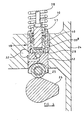
- Figure 4 illustrates a modification to the arrangement illustrated in Figures 1 to 3.
- the distance through which the piston member 19 can move relative to the tappet 22 is not controlled by controlling the point at which the chamber 28 moves into communication with a relief passage, but rather by providing the tappet 22 with a circlip 40 which is engageable with the piston member 19 upon movement of the piston member 19 by a predetermined distance.
- the screw-threaded pin 39 is replaced by a peg 39 a carried by the tappet 22 and slidable within a slot formed in the bore 23.
- Figure 5 illustrates an arrangement which is similar to that of Figure 4 but in which the piston member 19 and drive member 17 are formed integrally with one another, and denoted by reference numeral 19 a .
- a shim 20 a is provided to set the normal outermost position for the pumping plunger 10 and a shim 20 b is provided to set the position occupied by the pumping plunger 10 when the pump is operating under circumstances in which the timing of fuel delivery by the pump is advanced.
- the peg 39 a is of increased length and extends across the diameter of the tappet 22, extending through an opening formed in the drive member 17.
- the dimensions of the opening formed in the drive member 17 are chosen to limit the distance through which the piston member 19 can move relative to the tappet 22, thereby avoiding the necessity to provide the circlip or stop 40.
- Figure 7 illustrates a modification to the arrangement of Figure 6 in which the drive member 17 and piston member 19 are formed integrally with one another. Operation of these embodiments is substantially as described hereinbefore and so will not be described in further detail.
- Figure 8 illustrates an arrangement which operates in a manner similar to that of Figures 1 to 3, but in which a peg 39 a is used to ensure that the tappet 22 cannot move angularly relative to the housing 24, the peg 39 a extending into a recess formed in the piston member 19 to retain the piston member 19 in position, during assembly, but to allow free movement of the piston member 19 in use.
- the piston member 19 is of sufficient axial length that the drive member 17 can be omitted, the piston member 19 being secured to the pumping plunger 10.
- the relief passage 33 is defined by drillings formed in the piston member 19, the relief passage 33 being closed by the tappet 22 when the piston member 19 occupies a lower position relative to the tappet 32 and opening when the piston member 19 occupies a raised position relative to the tappet 22.
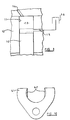
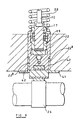
- Figures 9 and 10 illustrate an alternative technique for securing the tappet 22 against rotation or angular movement relative to the housing 24.
- the tappet 22 is shaped to define a pair of flats 22 a
- the housing 24 has secured thereto a yolk 41 including a pair of projections 42 which extend into the recesses defined between the flats 22 a of the tappet 22 and the bore 23.
- the cooperation between the flats 22 a and the projections 42 holds the tappet 22 against angular movement relative to the housing 24.
- One advantage of using this technique for holding the tappet 22 against angular movement is that there is no necessity to provide a tappet location feature at the upper end of the tappet 22 in the orientation illustrated.
- piston member 19 may be formed to include a region of part-spherical form, the part-spherical region engaging or cooperating with the surface of the bore formed in the tappet in such a manner that the axis of the piston member 19 need not be exactly coaxial with that of the tappet, but may be angled slightly thereto.
- the invention is particularly suitable for use in controlling the timing of fuel delivery and permitting the timing of such delivery to be advanced when an associated engine is cold.
- the oil pressure supplied to the supply passage 32 may be controlled using a suitable temperature sensitive valve. It will be appreciated, however, that the invention is suitable for use in other arrangements in which the timing of fuel delivery is to be controlled, and is not restricted to arrangements in which the timing of fuel delivery is modified to compensate for the engine operating temperature.
Landscapes
- Engineering & Computer Science (AREA)
- Chemical & Material Sciences (AREA)
- Combustion & Propulsion (AREA)
- Mechanical Engineering (AREA)
- General Engineering & Computer Science (AREA)
- Fuel-Injection Apparatus (AREA)
- High-Pressure Fuel Injection Pump Control (AREA)
Abstract
Description
Claims (19)
- A fuel pump comprising a pumping plunger (10) reciprocable within a plunger bore (11) under the action of a cam drive arrangement (18), the cam drive arrangement (18) comprising first and second surfaces defining therebetween a chamber (28), the volume of which can be controlled to control the spacing of the first and second surfaces, thereby permitting control of the axial length of the cam drive arrangement (18).
- The fuel pump as claimed in Claim 1, further comprising a filling port (15), the filling port (15) being obscured, in use, by the pumping plunger (10), whereby adjustment of the axial length of the cam drive arrangement (18) permits the timing at which the filling port (15) is obscured by the pumping plunger (10), and hence the timing of commencement of pressurisation of fuel by the pump, to be controlled.
- The fuel pump as claimed in Claim 1 or Claim 2, wherein the first surface is defined by a tappet member (22) which acts to transmit a force from the cam drive arrangement (18) to the pumping plunger (10).
- The fuel pump as claimed in Claim 3, wherein the second surface is defined by a piston member (19) slidable within a tappet bore (21) formed in the tappet member (22).
- The fuel pump as claimed in Claim 4, comprising a spring arrangement (36) arranged to apply a biasing force to the piston member (19) which tends to minimise the volume of the chamber (28).
- The fuel pump as claimed in Claim 4 or Claim 5, wherein the plunger bore (11) defines a pumping chamber (13) for fuel, reciprocal movement of the pumping plunger (10) within the plunger bore (11) causing fuel pressurisation within the pumping chamber (13), in use, the fuel pump further comprising a further spring arrangement (38) which is arranged to urge the tappet member (22) in a direction to withdraw the pumping plunger (10) from the plunger bore (11), thereby tending to maximise the volume of the pumping chamber (13).
- The fuel pump as claimed in any of Claims 4 to 6, wherein the cam drive arrangement (18) includes a drive member (17) which carries the piston member (19), a force from the piston member (19) being transmitted to the pumping plunger (10) through the drive member (17).
- The fuel pump as claimed in Claim 7, wherein the drive member (17) and the piston member (19) are integrally formed.
- The fuel pump as claimed in any of Claims 4 to 6, wherein the piston member (19) is secured directly to the pumping plunger (10).
- The fuel pump as claimed in any of Claims 4 to 9, wherein the tappet member (21) is shaped to define, at least in part, a relief passage (33) which communicates with the chamber (28) upon movement of the piston member (19) beyond a predetermined position.
- The fuel pump as claimed in any of Claims 4 to 9, wherein the tappet member (22) is provided with a circlip (40) which is engageable with the piston member (19) upon movement of the piston member (19) beyond a predetermined amount.
- The fuel pump as claimed in any of Claims 3 to 10, wherein the tappet member (22) is slidable within a further bore (23) provided in a housing (24), the fuel pump further comprising means (39, 39a) for substantially preventing angular movement of the tappet member (22) within the further bore (23).
- The fuel pump as claimed in Claim 12, wherein one of the tappet member (22) and the housing (24) is provided with a member (39, 39a) which extends into a recess provided in the other of the tappet member (22) and the housing (24) so as to substantially prevent angular movement of the tappet member (22) within the further bore (23).
- The fuel pump as claimed in Claim 12, wherein the tappet member (22) is provided with a peg (39a) which extends through an opening provided in a drive member (17) forming part of the drive arrangement (18) so as to substantially prevent angular movement of the tappet member (22) within the further bore (23).
- The fuel pump as claimed in Claim 12, comprising a yoke (41) secured to the housing (24), the yoke (41) having at least one projection (42) extending into the further bore (23) provided in the housing (24), the or each projection (42) cooperating with the tappet member (22) so as to substantially prevent angular movement of the tappet member (22) within the further bore (23).
- The fuel pump as claimed in any of Claims 4 to 15, wherein the piston member (19) includes a region of part-spherical form which is cooperable with the tappet bore (21) to permit axial misalignment between the piston member (19) and the tappet member (22).
- The fuel pump as claimed in any of Claims 1 to 16, wherein the chamber (28) is arranged to receive fluid through a supply passage (32), fluid pressure within the chamber (28) applying a force to the first and second surfaces which serves to increase the volume of the chamber (28).
- The fuel pump as claimed in Claim 17, further comprising a temperature sensitive valve arrangement, the pressure of fluid supplied to the chamber (28) being controlled in response to an output from the temperature sensitive valve arrangement.
- An arrangement (41, 42) for use in a fuel pump comprising a pumping plunger (10) which is reciprocable within a plunger bore (11) under the action of a drive arrangement (18) and a tappet member (22) which is slidable within a further bore (23) provided in a housing (24) for transmitting a force from the drive arrangement (18) to the pumping plunger (10), the arrangement comprising a yoke (41) secured to the housing (24), the yoke (41) having at least one projection (42) extending into the bore (23) provided in the housing (24), the or each projection (42) cooperating with the tappet member (22) so as to substantially prevent angular movement of the tappet member (22) within the further bore (23).
Applications Claiming Priority (2)
| Application Number | Priority Date | Filing Date | Title |
|---|---|---|---|
| GBGB9918871.6A GB9918871D0 (en) | 1999-08-10 | 1999-08-10 | Fuel pump |
| GB9918871 | 1999-08-10 |
Publications (2)
| Publication Number | Publication Date |
|---|---|
| EP1076173A2 true EP1076173A2 (en) | 2001-02-14 |
| EP1076173A3 EP1076173A3 (en) | 2003-01-15 |
Family
ID=10858921
Family Applications (1)
| Application Number | Title | Priority Date | Filing Date |
|---|---|---|---|
| EP00306748A Withdrawn EP1076173A3 (en) | 1999-08-10 | 2000-08-08 | Fuel pump |
Country Status (4)
| Country | Link |
|---|---|
| US (1) | US6406269B1 (en) |
| EP (1) | EP1076173A3 (en) |
| JP (1) | JP2001090632A (en) |
| GB (1) | GB9918871D0 (en) |
Cited By (3)
| Publication number | Priority date | Publication date | Assignee | Title |
|---|---|---|---|---|
| WO2004007948A1 (en) * | 2002-07-15 | 2004-01-22 | Robert Bosch Gmbh | Roller tappet with cold advance |
| EP1835168A1 (en) * | 2006-03-17 | 2007-09-19 | Delphi Technologies, Inc. | Fuel injection pump |
| WO2012104236A3 (en) * | 2011-01-31 | 2012-11-01 | Continental Automotive Gmbh | Pump unit for a high-pressure pump |
Families Citing this family (7)
| Publication number | Priority date | Publication date | Assignee | Title |
|---|---|---|---|---|
| US6619186B2 (en) * | 2000-11-09 | 2003-09-16 | Stanadyne Corporation | Servo controlled timing advance for unit pump or unit injector |
| US6733249B2 (en) | 2001-05-17 | 2004-05-11 | Delphi Technologies, Inc. | Multi-stage internal gear fuel pump |
| US6758656B2 (en) | 2001-05-17 | 2004-07-06 | Delphi Technologies, Inc. | Multi-stage internal gear/turbine fuel pump |
| US7513756B2 (en) * | 2002-10-29 | 2009-04-07 | Bosch Automotive Systems Corporation | Fuel supply pump and tappet structure body |
| US7311087B2 (en) * | 2004-11-23 | 2007-12-25 | Cummins Inc. | Fuel pump with a guided tappet assembly and methods for guiding and assembly |
| JP5984303B2 (en) * | 2011-12-28 | 2016-09-06 | 株式会社赤阪鉄工所 | Fuel injection auxiliary device and fuel injection pump provided with fuel injection auxiliary device |
| GB2534397A (en) * | 2015-01-22 | 2016-07-27 | Gm Global Tech Operations | Unit pump for use in a combustion engine |
Family Cites Families (7)
| Publication number | Priority date | Publication date | Assignee | Title |
|---|---|---|---|---|
| GB825136A (en) * | 1956-07-09 | 1959-12-09 | Napier & Son Ltd | Timing of fuel injection pumps |
| DE3206429C2 (en) * | 1982-02-23 | 1983-12-22 | Daimler-Benz Ag, 7000 Stuttgart | Hydraulic adjusting device for influencing the start of injection of an injection pump intended for compression-ignition internal combustion engines |
| DE3510223A1 (en) * | 1985-03-21 | 1986-10-02 | Daimler-Benz Ag, 7000 Stuttgart | Hydraulic adjusting device for influencing the start of injection of an injection pump intended for self-ignition internal combustion engines |
| US4861243A (en) * | 1988-04-08 | 1989-08-29 | Ford Motor Company | Diesel fuel injection pump with variable injection timing |
| DE4118555A1 (en) * | 1991-06-06 | 1992-12-10 | Bosch Gmbh Robert | CONVEYOR ADJUSTMENT DEVICE OF A FUEL INJECTION PUMP |
| DE4215665A1 (en) * | 1992-05-13 | 1993-11-18 | Bosch Gmbh Robert | Fuel injection pump for IC engine - has non-return valve, which is opened dependent upon engine temperature by expansion element |
| DE4227853C2 (en) * | 1992-08-22 | 1996-05-30 | Bosch Gmbh Robert | Fuel injection pump for internal combustion engines |
-
1999
- 1999-08-10 GB GBGB9918871.6A patent/GB9918871D0/en not_active Ceased
-
2000
- 2000-08-08 EP EP00306748A patent/EP1076173A3/en not_active Withdrawn
- 2000-08-08 US US09/634,517 patent/US6406269B1/en not_active Expired - Lifetime
- 2000-08-10 JP JP2000242966A patent/JP2001090632A/en not_active Withdrawn
Cited By (9)
| Publication number | Priority date | Publication date | Assignee | Title |
|---|---|---|---|---|
| WO2004007948A1 (en) * | 2002-07-15 | 2004-01-22 | Robert Bosch Gmbh | Roller tappet with cold advance |
| US7044095B2 (en) | 2002-07-15 | 2006-05-16 | Robert Bosch Gmbh | Roller tappet with cold advance |
| EP1835168A1 (en) * | 2006-03-17 | 2007-09-19 | Delphi Technologies, Inc. | Fuel injection pump |
| US7509947B2 (en) | 2006-03-17 | 2009-03-31 | Delphi Technologies, Inc. | Fuel injection pump |
| WO2012104236A3 (en) * | 2011-01-31 | 2012-11-01 | Continental Automotive Gmbh | Pump unit for a high-pressure pump |
| CN103443440A (en) * | 2011-01-31 | 2013-12-11 | 大陆汽车有限公司 | Pump unit for a high-pressure pump |
| CN103443440B (en) * | 2011-01-31 | 2016-02-24 | 大陆汽车有限公司 | For the pump unit of high-pressure service pump |
| EP3059438A1 (en) * | 2011-01-31 | 2016-08-24 | Continental Automotive GmbH | Pump unit for a high-pressure pump |
| US10047740B2 (en) | 2011-01-31 | 2018-08-14 | Continental Automotive Gmbh | Pump unit for a high-pressure pump |
Also Published As
| Publication number | Publication date |
|---|---|
| GB9918871D0 (en) | 1999-10-13 |
| EP1076173A3 (en) | 2003-01-15 |
| JP2001090632A (en) | 2001-04-03 |
| US6406269B1 (en) | 2002-06-18 |
Similar Documents
| Publication | Publication Date | Title |
|---|---|---|
| US6457957B1 (en) | Radial piston pump for generating high fuel pressure | |
| EP0943797A1 (en) | Fuel injector | |
| EP0889230A2 (en) | Fuel injector | |
| US6406269B1 (en) | Fuel pump | |
| EP1651863B1 (en) | Common rail fuel pump | |
| EP0957261A2 (en) | Fuel system and pump suitable for use therein | |
| US6439204B1 (en) | Timing advance piston for unit pump or unit injector and method thereof | |
| EP1098087B1 (en) | Fuel Injector | |
| US7850435B2 (en) | Fuel injection device for an internal combustion engine | |
| WO1993006361A1 (en) | Fuel injection pump | |
| CN1466655A (en) | Fuel injection devices for internal combustion engines | |
| EP1072785A2 (en) | Fuel pump | |
| US5546906A (en) | Fuel injection pump | |
| EP1065368A2 (en) | Fuel injector | |
| EP0821154A1 (en) | Fuel pumping apparatus | |
| JPS6146459A (en) | Fuel jet pump of internal combustion engine | |
| JPS61190164A (en) | Fuel injection pump for diesel engine | |
| US6447263B1 (en) | Fuel pump with auxiliary pumping chamber | |
| US6908043B2 (en) | Fuel injection device for internal combustion engines | |
| JPH01203651A (en) | Fuel injection pump | |
| EP0458529A1 (en) | Fuel pumping apparatus | |
| JPH0223822Y2 (en) | ||
| WO1993021439A1 (en) | Fuel pump | |
| GB2283539A (en) | Fuel pumping apparatus | |
| WO1993019292A1 (en) | Fuel pump |
Legal Events
| Date | Code | Title | Description |
|---|---|---|---|
| PUAI | Public reference made under article 153(3) epc to a published international application that has entered the european phase |
Free format text: ORIGINAL CODE: 0009012 |
|
| AK | Designated contracting states |
Kind code of ref document: A2 Designated state(s): AT BE CH CY DE DK ES FI FR GB GR IE IT LI LU MC NL PT SE |
|
| AX | Request for extension of the european patent |
Free format text: AL;LT;LV;MK;RO;SI |
|
| PUAL | Search report despatched |
Free format text: ORIGINAL CODE: 0009013 |
|
| AK | Designated contracting states |
Kind code of ref document: A3 Designated state(s): AT BE CH CY DE DK ES FI FR GB GR IE IT LI LU MC NL PT SE |
|
| AX | Request for extension of the european patent |
Free format text: AL;LT;LV;MK;RO;SI |
|
| RIC1 | Information provided on ipc code assigned before grant |
Free format text: 7F 02M 57/02 A, 7F 02M 59/10 B, 7F 02M 59/30 B |
|
| AKX | Designation fees paid | ||
| REG | Reference to a national code |
Ref country code: DE Ref legal event code: 8566 |
|
| STAA | Information on the status of an ep patent application or granted ep patent |
Free format text: STATUS: THE APPLICATION IS DEEMED TO BE WITHDRAWN |
|
| 18D | Application deemed to be withdrawn |
Effective date: 20030716 |