EP1075608B1 - Braking system incorporating a liquid-cooled brake - Google Patents
Braking system incorporating a liquid-cooled brake Download PDFInfo
- Publication number
- EP1075608B1 EP1075608B1 EP99918185A EP99918185A EP1075608B1 EP 1075608 B1 EP1075608 B1 EP 1075608B1 EP 99918185 A EP99918185 A EP 99918185A EP 99918185 A EP99918185 A EP 99918185A EP 1075608 B1 EP1075608 B1 EP 1075608B1
- Authority
- EP
- European Patent Office
- Prior art keywords
- brake
- circuit
- braking system
- cooling liquid
- liquid
- Prior art date
- Legal status (The legal status is an assumption and is not a legal conclusion. Google has not performed a legal analysis and makes no representation as to the accuracy of the status listed.)
- Expired - Lifetime
Links
- 239000000110 cooling liquid Substances 0.000 claims description 17
- 239000007788 liquid Substances 0.000 claims description 7
- 230000001419 dependent effect Effects 0.000 claims description 2
- 239000012809 cooling fluid Substances 0.000 claims 2
- 238000001816 cooling Methods 0.000 description 6
- 238000009434 installation Methods 0.000 description 2
- 230000004913 activation Effects 0.000 description 1
- 230000001934 delay Effects 0.000 description 1
- 230000003111 delayed effect Effects 0.000 description 1
- 230000000994 depressogenic effect Effects 0.000 description 1
- 230000000694 effects Effects 0.000 description 1
- 238000013021 overheating Methods 0.000 description 1
- 238000005086 pumping Methods 0.000 description 1
Images
Classifications
-
- F—MECHANICAL ENGINEERING; LIGHTING; HEATING; WEAPONS; BLASTING
- F16—ENGINEERING ELEMENTS AND UNITS; GENERAL MEASURES FOR PRODUCING AND MAINTAINING EFFECTIVE FUNCTIONING OF MACHINES OR INSTALLATIONS; THERMAL INSULATION IN GENERAL
- F16D—COUPLINGS FOR TRANSMITTING ROTATION; CLUTCHES; BRAKES
- F16D65/00—Parts or details
- F16D65/78—Features relating to cooling
-
- F—MECHANICAL ENGINEERING; LIGHTING; HEATING; WEAPONS; BLASTING
- F16—ENGINEERING ELEMENTS AND UNITS; GENERAL MEASURES FOR PRODUCING AND MAINTAINING EFFECTIVE FUNCTIONING OF MACHINES OR INSTALLATIONS; THERMAL INSULATION IN GENERAL
- F16D—COUPLINGS FOR TRANSMITTING ROTATION; CLUTCHES; BRAKES
- F16D65/00—Parts or details
- F16D65/78—Features relating to cooling
- F16D2065/783—Features relating to cooling cooling control or adjustment
-
- F—MECHANICAL ENGINEERING; LIGHTING; HEATING; WEAPONS; BLASTING
- F16—ENGINEERING ELEMENTS AND UNITS; GENERAL MEASURES FOR PRODUCING AND MAINTAINING EFFECTIVE FUNCTIONING OF MACHINES OR INSTALLATIONS; THERMAL INSULATION IN GENERAL
- F16D—COUPLINGS FOR TRANSMITTING ROTATION; CLUTCHES; BRAKES
- F16D65/00—Parts or details
- F16D65/78—Features relating to cooling
- F16D2065/787—Pumps
Definitions
- This invention relates to a braking system of the kind incorporating a liquid-cooled brake, primarily for a vehicle, the brake having a housing within which are provided cooperating fixed and rotatable braking surfaces which are brought into braking engagement upon operation of actuating means.
- US3882930 shows a brake, wherein a variable cooling flow to the brake can be provided depending upon operation parameters.
- the cooling liquid in the first circuit is supplied to the brake at relatively low pressure and the cooling liquid in the second circuit is supplied to the brake at relatively high pressure.
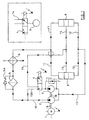
- the braking system illustrated in Figure 1 includes a drive motor 1 having a driving connection, illustrated at 1A, 1B with a pair of pumps 2, 3 which respectively provide a relatively high liquid flow rate at relatively low pressure and a relatively low flow rate at relatively high pressure.
- the pumps may, alternatively, be driven independently by separate motors.
- the cooling liquid would, in practice, be oil present in the hydraulic system and/or gearbox of a vehicle on which the system is installed.
- the output from the pump 2 enters a low pressure line 10 and is directed through a filter 5, which is protected against excessive pressure by a non-return valve 5A, the filtered oil leaving the filter 5 passing through a heat exchanger 6 of any appropriate type and thence to a branch line 11 which directs the oil through a pair of brakes 8.
- the pump motor is controlled, in a manner to be described hereafter, to be switched on whenever the temperature of the oil leaving the brake exceeds a predetermined value, e.g. 70°C, or during brake application. Oil heated by passage through the brakes is directed by lines 12 into a return line 13, from which it re-enters the pumps 2 and 3 for re-circulation.
- a predetermined value e.g. 70°C
- the output from the pump 3 is fed via a two-position solenoid-operated valve 4, conveniently a spool valve, which, in the position illustrated, directs the output from the pump 3 to the low pressure line 10 via a branch line 10A.
- a pressure relief valve 7 may be provided in parallel with the pump 3 to protect against excessively high pressure peaks in the high pressure circuit.
- the oil may conveniently be fed along the shaft to a central region of the brake adjacent the friction plates. Heated oil from the brakes leaves via the lines 12 and is directed via line 13 to the pumps and recirculated through the brakes via the heat exchanger 6.
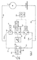
- the supply of cooling liquid in the braking system of the invention is controlled by the circuit illustrated in Figure 2, in which the drive motor/pump unit is designated M.
- An electrical supply circuit is established through lines 30 and 31 and a temperature sensitive switch device 32 incorporating a switch 33.
- the switch device 32 incorporates a temperature sensing thermostat 34 and a timer device 35.
- the lines 31 also supply, via branches 31A.
- the solenoid 4A operating the valve 4 the operation of the solenoid being dependent upon a switch 36 activated by a driver-operated control B, such as a pedal, the switch itself being controlled by a timer device 37 incorporating a delay device 37A.
- Both the timer 37 and switch 38 are subject to a speed sensitive device 39, switch 38 being closed only if the vehicle speed is greater than 1 metre per second.
- the switch 36 may conveniently be a pressure switch, a brake light switch or any other appropriate switch device. If the vehicle is stationary, or its speed is less than 1 metre per second, the heat generated therein is not sufficiently high to require the supply of high pressure cooling oil and the switch 38 remains open, preventing activation of the solenoid 4A, so that the valve 4 is in the position illustrated in the main part of Figure 1. Both pumps then supply oil to the low pressure circuit, the pump 3 via the branch 10A.
- the brake is cooled by the supply of low pressure oil, until such time as the temperature of the oil leaving the brakes, as sensed by the thermostat 34 of the switch device 32, is 70°C or less, whereupon the thermostat provides a signal which first activates the timer 35, enabling the supply of low pressure oil to continue for a short time, e.g. 10 seconds, before the switch 33 is operated to de-activate the motor/pump unit.
- switch 38 closes and switch 36 is closed by the brake pedal to actuate the solenoid 4A, which changes over the valve 4 to its alternative position illustrated inset in Figure 1, enabling high pressure oil to be supplied to the brakes for cooling.
- the brake pedal B is released, if the vehicle is still travelling at more than 1 metre per second, opening of the switch 36 will be delayed for a predetermined time set by the delay device 37A, permitting the continued supply of high pressure oil to ensure that the linings are cooled to the temperature of the cooling oil.
- the effect of this is to ensure that heat transfer from the linings into the low pressure oil circuit during each brake application takes place at the lowest possible temperature level. Furthermore, it prevents the pump drive motor from overheating when the brake is re-applied at intervals of less than the delay set by the timer, such as may occur in dense traffic conditions, for example, when pumping of the brake pedal may take place.
- twin cooling circuits of the system of the invention may be controlled to operate in any convenient manner in order to fulfil the requirements of a particular installation and the described sequence of switching according to timed delays may be varied as required, both as regards the sequence itself and the control means employed.
Landscapes
- Engineering & Computer Science (AREA)
- General Engineering & Computer Science (AREA)
- Mechanical Engineering (AREA)
- Braking Arrangements (AREA)
Description
Claims (9)
- A braking system comprising a liquid-cooled brake (8) having a housing within which are provided co-operating fixed and rotatable braking surfaces which are brought into braking engagement upon operation of actuating means, a first flow circuit (10, 10A, 11 ) arranged to supply cooling liquid to the brake via the first flow circuit in dependence upon a temperature dependent operational parameter for maintaining the temperature of cooling liquid in the system below a predetermined maximum value, and a second flow circuit (14, 15) controllable to supply cooling liquid to the brake via the second flow circuit, separate from the first flow circuit, upon brake actuation.
- A braking system as claimed in claim 1, wherein the cooling liquid in the first circuit is supplied to the brake at relatively low pressure and the cooling liquid in the second circuit is simultaneously supplied to the brake at relatively high pressure.
- A braking system as claimed in claim 2 wherein the liquid cooled brake is an oil immersed disc brake having a central drive shaft and the cooling liquid in the second circuit is supplied to the brake at relatively high pressure by being fed along the shaft to a central region of the brake adjacent friction plates.
- A braking system as claimed in any one of the preceding claims, wherein the first circuit includes a heat exchanger (6) through which the cooling liquid in that circuit passes.
- A braking system as claimed in any one of the preceding claims, wherein the cooling liquid is circulated in the low flow circuits by electrically driven (1) liquid propulsion means (2, 3) operated by an electrical supply circuit serving to control the supply of cooling liquid to the brake.
- A braking system as claimed in Claim 5, wherein the liquid propulsion means comprises at least one electric motor (1) and pumps (23) driven by at least one motor for respectively circulating cooling liquid in the first and second flow circuits.
- A braking system as claimed in claim 6, wherein the electrical supply circuit serves to cause cooling fluid to be supplied from both pumps to the brake through the first flow circuit when no cooling fluid is circulating in the second flow circuit.
- A braking system as claimed in claim 5, 6 or 7 wherein the electrical supply circuit comprises a temperature sensitive switch (32) in parallel with a further switch (36) operated by a driver-operated control device (B) for actuating the brake, the further switch being connected to an electrically operated valve (4) serving to control the flow of cooling liquid in the second liquid circuit.
- A braking system according to claim 8, wherein the electrically operated valve (4) is influenced by a speed-sensitive device sensing vehicle speed.
Applications Claiming Priority (3)
| Application Number | Priority Date | Filing Date | Title |
|---|---|---|---|
| GB9808984 | 1998-04-29 | ||
| GBGB9808984.0A GB9808984D0 (en) | 1998-04-29 | 1998-04-29 | Braking system incorporating a liquid cooled brake |
| PCT/GB1999/001331 WO1999056032A1 (en) | 1998-04-29 | 1999-04-29 | Braking system incorporating a liquid-cooled brake |
Publications (2)
| Publication Number | Publication Date |
|---|---|
| EP1075608A1 EP1075608A1 (en) | 2001-02-14 |
| EP1075608B1 true EP1075608B1 (en) | 2004-06-23 |
Family
ID=10831062
Family Applications (1)
| Application Number | Title | Priority Date | Filing Date |
|---|---|---|---|
| EP99918185A Expired - Lifetime EP1075608B1 (en) | 1998-04-29 | 1999-04-29 | Braking system incorporating a liquid-cooled brake |
Country Status (4)
| Country | Link |
|---|---|
| EP (1) | EP1075608B1 (en) |
| DE (1) | DE69918294T2 (en) |
| GB (1) | GB9808984D0 (en) |
| WO (1) | WO1999056032A1 (en) |
Cited By (1)
| Publication number | Priority date | Publication date | Assignee | Title |
|---|---|---|---|---|
| DE102009015937A1 (en) * | 2009-04-02 | 2010-10-14 | Knorr-Bremse Systeme für Nutzfahrzeuge GmbH | Wet running multi-disc brake |
Families Citing this family (3)
| Publication number | Priority date | Publication date | Assignee | Title |
|---|---|---|---|---|
| DE102009026985A1 (en) * | 2009-06-17 | 2011-03-31 | Zf Friedrichshafen Ag | Arrangement for cooling and/or lubricating lamella package of e.g. multi-disk clutch of industrial lorry, has pump providing coolant and/or lubricant stream whose flow rate is electronically controlled by electronic control device |
| US10850960B2 (en) | 2015-12-08 | 2020-12-01 | Doosan Corporation | Cooling device for forklift brake system |
| FR3107869B1 (en) * | 2020-03-03 | 2022-02-11 | Psa Automobiles Sa | MECHATRONIC BRAKING ASSISTANCE DEVICE WITH COOLING CONTROL, SYSTEM AND VEHICLE COMPRISING SUCH A DEVICE |
Family Cites Families (5)
| Publication number | Priority date | Publication date | Assignee | Title |
|---|---|---|---|---|
| GB1291722A (en) * | 1969-07-29 | 1972-10-04 | Ferodo Ltd | Vehicle retarder systems |
| US3882930A (en) * | 1973-11-01 | 1975-05-13 | Caterpillar Tractor Co | Cooling system for brakes |
| US3949844A (en) * | 1974-11-15 | 1976-04-13 | Caterpillar Tractor Co. | Brake cooling system with a common fluid mixing chamber |
| DE3518795A1 (en) * | 1985-05-24 | 1986-11-27 | Lucas Industries P.L.C., Birmingham, West Midlands | DEVICE FOR COOLING THE HYDRAULIC LIQUID OF A BRAKE SYSTEM |
| US5445242A (en) * | 1993-08-27 | 1995-08-29 | Pogorzelski; Thomas J. | Disc brake caliper with auxiliary system to cool brake fluid |
-
1998
- 1998-04-29 GB GBGB9808984.0A patent/GB9808984D0/en not_active Ceased
-
1999
- 1999-04-29 WO PCT/GB1999/001331 patent/WO1999056032A1/en not_active Ceased
- 1999-04-29 DE DE69918294T patent/DE69918294T2/en not_active Expired - Fee Related
- 1999-04-29 EP EP99918185A patent/EP1075608B1/en not_active Expired - Lifetime
Cited By (1)
| Publication number | Priority date | Publication date | Assignee | Title |
|---|---|---|---|---|
| DE102009015937A1 (en) * | 2009-04-02 | 2010-10-14 | Knorr-Bremse Systeme für Nutzfahrzeuge GmbH | Wet running multi-disc brake |
Also Published As
| Publication number | Publication date |
|---|---|
| WO1999056032A1 (en) | 1999-11-04 |
| DE69918294D1 (en) | 2004-07-29 |
| GB9808984D0 (en) | 1998-06-24 |
| DE69918294T2 (en) | 2005-08-04 |
| EP1075608A1 (en) | 2001-02-14 |
Similar Documents
| Publication | Publication Date | Title |
|---|---|---|
| JP4257880B2 (en) | Hydraulic control unit | |
| US5169214A (en) | Hydraulic multi-circuit brake system including a traction and anti-skid control device for motor vehicles | |
| EP0812280B1 (en) | Automotive hydraulic system and method | |
| CA2178980C (en) | Electrohydraulic parking brake control system for preventing brake engagement when vehicle is in motion | |
| CN101541601A (en) | Control device for cooling fan for vehicle | |
| KR960700165A (en) | Vehicle hydraulio brake system operating with power assistance | |
| JP2009541128A (en) | Fluid retarder | |
| CN112065564B (en) | A vehicle cooling system, control method and vehicle | |
| KR100347645B1 (en) | Brake unit with vehicle anti-lock brake system | |
| US4817767A (en) | Hydraulic brake system for automotive vehicles | |
| US4088208A (en) | Transmission disconnect system | |
| US5507360A (en) | Hydraulic system for dynamic braking and secondary steering system supply | |
| WO1999056032A1 (en) | Braking system incorporating a liquid-cooled brake | |
| GB1459886A (en) | Motor vehicle braking systems | |
| US7526916B2 (en) | Drive train | |
| CN114787005A (en) | Speed reducer with heat exchanger | |
| EP1561963B1 (en) | Method and circuit for controlling the flow rate of the hydraulic oil in the brake cooling system of a vehicle | |
| JPH10114243A (en) | Drive unit with motor and retarder | |
| EP0507745A2 (en) | A control system for a hydraulic retarder for commercial vehicles and a vehicle with the system | |
| US4453512A (en) | Engine overheat prevention system | |
| JP2005289158A (en) | Wheel-in motor cooling method, foil-in motor cooling device | |
| JP2000065106A (en) | Electronically controlled ventilation system for disc brakes | |
| RU2273570C2 (en) | Wheeled vehicle | |
| JPH1076930A (en) | Multi-circuit type vehicle brake system | |
| CN116985772A (en) | Braking systems and motor vehicles with bypass lines |
Legal Events
| Date | Code | Title | Description |
|---|---|---|---|
| PUAI | Public reference made under article 153(3) epc to a published international application that has entered the european phase |
Free format text: ORIGINAL CODE: 0009012 |
|
| 17P | Request for examination filed |
Effective date: 20001020 |
|
| AK | Designated contracting states |
Kind code of ref document: A1 Designated state(s): DE ES FR GB IT |
|
| 17Q | First examination report despatched |
Effective date: 20021114 |
|
| GRAP | Despatch of communication of intention to grant a patent |
Free format text: ORIGINAL CODE: EPIDOSNIGR1 |
|
| GRAS | Grant fee paid |
Free format text: ORIGINAL CODE: EPIDOSNIGR3 |
|
| GRAA | (expected) grant |
Free format text: ORIGINAL CODE: 0009210 |
|
| AK | Designated contracting states |
Kind code of ref document: B1 Designated state(s): DE ES FR GB IT |
|
| REG | Reference to a national code |
Ref country code: GB Ref legal event code: FG4D |
|
| REF | Corresponds to: |
Ref document number: 69918294 Country of ref document: DE Date of ref document: 20040729 Kind code of ref document: P |
|
| PG25 | Lapsed in a contracting state [announced via postgrant information from national office to epo] |
Ref country code: ES Free format text: LAPSE BECAUSE OF FAILURE TO SUBMIT A TRANSLATION OF THE DESCRIPTION OR TO PAY THE FEE WITHIN THE PRESCRIBED TIME-LIMIT Effective date: 20041004 |
|
| ET | Fr: translation filed | ||
| PLBE | No opposition filed within time limit |
Free format text: ORIGINAL CODE: 0009261 |
|
| STAA | Information on the status of an ep patent application or granted ep patent |
Free format text: STATUS: NO OPPOSITION FILED WITHIN TIME LIMIT |
|
| 26N | No opposition filed |
Effective date: 20050324 |
|
| PGFP | Annual fee paid to national office [announced via postgrant information from national office to epo] |
Ref country code: FR Payment date: 20060410 Year of fee payment: 8 |
|
| PGFP | Annual fee paid to national office [announced via postgrant information from national office to epo] |
Ref country code: GB Payment date: 20060426 Year of fee payment: 8 |
|
| PGFP | Annual fee paid to national office [announced via postgrant information from national office to epo] |
Ref country code: DE Payment date: 20060427 Year of fee payment: 8 |
|
| GBPC | Gb: european patent ceased through non-payment of renewal fee |
Effective date: 20070429 |
|
| PGFP | Annual fee paid to national office [announced via postgrant information from national office to epo] |
Ref country code: IT Payment date: 20070630 Year of fee payment: 9 |
|
| PG25 | Lapsed in a contracting state [announced via postgrant information from national office to epo] |
Ref country code: DE Free format text: LAPSE BECAUSE OF NON-PAYMENT OF DUE FEES Effective date: 20071101 |
|
| PG25 | Lapsed in a contracting state [announced via postgrant information from national office to epo] |
Ref country code: GB Free format text: LAPSE BECAUSE OF NON-PAYMENT OF DUE FEES Effective date: 20070429 |
|
| PG25 | Lapsed in a contracting state [announced via postgrant information from national office to epo] |
Ref country code: FR Free format text: LAPSE BECAUSE OF NON-PAYMENT OF DUE FEES Effective date: 20070430 |
|
| PG25 | Lapsed in a contracting state [announced via postgrant information from national office to epo] |
Ref country code: IT Free format text: LAPSE BECAUSE OF NON-PAYMENT OF DUE FEES Effective date: 20080429 |