EP1075607B1 - Liquid-immersed disc brake - Google Patents
Liquid-immersed disc brake Download PDFInfo
- Publication number
- EP1075607B1 EP1075607B1 EP99918150A EP99918150A EP1075607B1 EP 1075607 B1 EP1075607 B1 EP 1075607B1 EP 99918150 A EP99918150 A EP 99918150A EP 99918150 A EP99918150 A EP 99918150A EP 1075607 B1 EP1075607 B1 EP 1075607B1
- Authority
- EP
- European Patent Office
- Prior art keywords
- shaft
- sleeve
- brake according
- liquid
- housing
- Prior art date
- Legal status (The legal status is an assumption and is not a legal conclusion. Google has not performed a legal analysis and makes no representation as to the accuracy of the status listed.)
- Expired - Lifetime
Links
- 239000007788 liquid Substances 0.000 claims description 9
- 238000001816 cooling Methods 0.000 claims description 5
- 239000000110 cooling liquid Substances 0.000 claims description 5
- 238000007789 sealing Methods 0.000 claims description 5
- 230000002093 peripheral effect Effects 0.000 claims description 2
- 230000000295 complement effect Effects 0.000 description 1
- 238000004519 manufacturing process Methods 0.000 description 1
- 239000000463 material Substances 0.000 description 1
- 239000002184 metal Substances 0.000 description 1
- 229920003023 plastic Polymers 0.000 description 1
- 239000004033 plastic Substances 0.000 description 1
- 238000000926 separation method Methods 0.000 description 1
Images
Classifications
-
- F—MECHANICAL ENGINEERING; LIGHTING; HEATING; WEAPONS; BLASTING
- F16—ENGINEERING ELEMENTS AND UNITS; GENERAL MEASURES FOR PRODUCING AND MAINTAINING EFFECTIVE FUNCTIONING OF MACHINES OR INSTALLATIONS; THERMAL INSULATION IN GENERAL
- F16D—COUPLINGS FOR TRANSMITTING ROTATION; CLUTCHES; BRAKES
- F16D55/00—Brakes with substantially-radial braking surfaces pressed together in axial direction, e.g. disc brakes
- F16D55/24—Brakes with substantially-radial braking surfaces pressed together in axial direction, e.g. disc brakes with a plurality of axially-movable discs, lamellae, or pads, pressed from one side towards an axially-located member
- F16D55/26—Brakes with substantially-radial braking surfaces pressed together in axial direction, e.g. disc brakes with a plurality of axially-movable discs, lamellae, or pads, pressed from one side towards an axially-located member without self-tightening action
- F16D55/36—Brakes with a plurality of rotating discs all lying side by side
-
- F—MECHANICAL ENGINEERING; LIGHTING; HEATING; WEAPONS; BLASTING
- F16—ENGINEERING ELEMENTS AND UNITS; GENERAL MEASURES FOR PRODUCING AND MAINTAINING EFFECTIVE FUNCTIONING OF MACHINES OR INSTALLATIONS; THERMAL INSULATION IN GENERAL
- F16D—COUPLINGS FOR TRANSMITTING ROTATION; CLUTCHES; BRAKES
- F16D65/00—Parts or details
- F16D65/78—Features relating to cooling
- F16D65/84—Features relating to cooling for disc brakes
- F16D65/853—Features relating to cooling for disc brakes with closed cooling system
-
- F—MECHANICAL ENGINEERING; LIGHTING; HEATING; WEAPONS; BLASTING
- F16—ENGINEERING ELEMENTS AND UNITS; GENERAL MEASURES FOR PRODUCING AND MAINTAINING EFFECTIVE FUNCTIONING OF MACHINES OR INSTALLATIONS; THERMAL INSULATION IN GENERAL
- F16D—COUPLINGS FOR TRANSMITTING ROTATION; CLUTCHES; BRAKES
- F16D55/00—Brakes with substantially-radial braking surfaces pressed together in axial direction, e.g. disc brakes
- F16D2055/0004—Parts or details of disc brakes
- F16D2055/0058—Fully lined, i.e. braking surface extending over the entire disc circumference
Definitions
- This invention relates to a liquid-immersed disc brake, primarily for a vehicle, the brake having a housing which contains at least one friction element rotatable with a rotary member to be braked and providing a first braking surface, a torque-resisting member providing a second braking surface which is relatively fixed, actuator means operable to bring the first and second surfaces into braking engagement, and means for supplying cooling liquid to the housing in cooling relationship with said surfaces.
- EP-A-053 8023 shows one form of liquid-immersed disc brake.
- An object of the invention is to provide an improved liquid-immersed disc brake in which the aforesaid difficulties are alleviated or avoided.
- the rotary member to be braked is drivingly connected to said at least one friction element via an intermediate member which provides a further part of said path serving to direct the introduced liquid towards said region.
- the rotary member is a shaft and the intermediate member is a sleeve surrounding and keyed to the shaft, preferably by one or more interengaged splines respectively on the shaft and sleeve, the sleeve being also keyed to said at least one friction element so as to be fast for rotation with the element and to permit axial movement of the at least one element along the shaft, the sleeve having one or more passages therein forming part of said path, and preferably extending radially through the sleeve peripheral wall.
- the core member is supported by the pressure plates and, in one convenient arrangement in which a pair of separable pressure plates is provided, the core member is fast for axial movement with one plate and axially slidable relative to the other plate.
- the core member may conveniently be formed integrally with said one pressure plate.
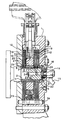
- the illustrated oil immersed disc brake has a housing 1, through which extends a rotary member to be braked, illustrated as a shaft 2 rotatably mounted in the housing.
- the shaft is externally splined at 3 and surrounded by a sleeve 4 which has complementary internal splines 5 engaged with those of the shaft so that the sleeve is rotatably keyed to the shaft.
- the sleeve is also externally splined at 6 and carries a plurality of rotary friction discs 7 which are arranged in two axially spaced groups and keyed to the external splines 6 of the sleeve by way of projecting lugs 8 so as to be fast for rotation with the sleeve but axially movable relative thereto, when required.
- Interleaved with the rotary discs 7 are further friction discs 9 which freely surround the shaft and are keyed against rotation in the housing by way of one or more abutment pins 9A.
- a pair of actuator plates 10, 11, Disposed between the groups of discs is a pair of actuator plates 10, 11, which are separable by a convenient form of primary actuator, such as a ball and ramp, wedge or other mechanism, to compress the groups of friction discs between opposed pairs of braking surfaces 12, 13 formed respectively on the internal surface of the housing and on the actuator plates 10 and 11, braking torque arising on the actuator plates being resisted by the housing, in known manner.
- a convenient form of primary actuator such as a ball and ramp, wedge or other mechanism
- the invention is particularly concerned with the manner in which cooling liquid is supplied to the friction discs at least during braking.
- Liquid enters the brake via a pipe 15 connected to an external boss 16, of which a smaller diameter portion 17 is screwed into the housing.
- a sealing device, indicated generally at 18 includes an annular collar 19 mounted in the housing by way of pins 20 and being urged by at least one spring 21 against the adjacent end of the shaft 2.
- the collar 19 carries a seal element 22, which largely precludes the flow of oil around the outside of the collar and ensures that oil flows predominantly from the boss 16 along a central axial passage 23 of the shaft and into radial passages 24 which direct the liquid into the interior of the sleeve 4.
- the seal element 22 seals against the end face of the shaft around the entrance to the passage 23.
- the sleeve 4 is provided, at locations conveniently adjacent the groups of disc 7, 9, with radial through holes 25 providing communication between the interior of the sleeve and optimum locations within the housing for distribution of liquid to the plates. Liquid entering the interior of the sleeve via the radial passages 24 is able to pass along axial passages formed by the shaft splines and those of the surrounding sleeve and thence through the holes 25 to the aforesaid locations. Appropriate internal splines of the sleeve 4, or splines of the shaft 3, or both such splines, may be omitted to provide a flow path of increased volume.
- a further feature of the described embodiment resides in the provision of an annular core member 26, of metal or plastics material for example, which lies in the space defined in part by each of the radially innermost surfaces of the actuator plates 10, 11, the inner surfaces of the innermost plates 7 and the external surface of the shaft 2.
- the core member 26 is mounted securely on the actuator plate 11, as by press fitting for example, the plate 11 having an annular recess within which is received a small annular shoulder 27 of the core member.
- the other actuator plate 10 is slidably mounted around the core member, a seal 28 being provided between the plate 10 and core member. The seal 28 prevents oil escaping through the actuation plates 10 and 11 when they are moved apart for brake actuation.
- the core 26 and pressure plate 11 may be convenient to manufacture as a unitary component. It will be seen that, upon separation of the plates 10 and 11 for brake actuation, the core member 26 moves with the plate 11, whilst performing a sliding movement relative to the plate 10.
- the function of the core member is to minimise the liquid capacity of the brake by filling a redundant area which would otherwise fill with cooling liquid during brake actuation.
- return springs 29 for the actuator plates 10 and 11, one of which springs can be seen in the drawing are accommodated in a radially outer region of the housing rather than, in conventional manner, in the central region of the brake.
Landscapes
- Engineering & Computer Science (AREA)
- General Engineering & Computer Science (AREA)
- Mechanical Engineering (AREA)
- Braking Arrangements (AREA)
Description
Claims (11)
- A liquid-immersed disc brake comprising a housing (1) containing at least one friction element (7) rotatable with a rotary member (2) to be braked and providing a first braking surface, a torque-resisting member (9) providing a second braking surface which is relatively fixed, actuator means operable to bring the first and second surfaces into braking engagement, the actuator means including at least one annular pressure plate (11) operable to move the friction element axially to cause engagement of the braking surfaces, the housing further including means for receiving cooling liquid in cooling relationship with said surfaces, characterised in that the pressure plate (11) surroundings a core member (26) which is supported for longitudinal movement relative to the rotary member and substantially fills the annular space formed between the exterior of the rotary member and the internal extremity of the or each plate (10, 11).
- A brake according to Claim 1, wherein the core member (26) is supported by the pressure plate (11).
- A brake according to Claim 2, wherein a pair of separable pressure plates (10, 11) is provided and the core member (26) is fast for axial movement with one plate (11) and axially slidable relative to the other plate (10).
- A brake according to Claim 3, wherein the core member is formed integrally with said one pressure plate.
- A brake according to any one of the preceding claims, comprising means for supplying cooling liquid to the housing (1) in cooling relationship with said surfaces, the rotary member providing at least a part of a path (23, 24) serving to direct liquid which has been introduced to the housing towards a region from which the introduced liquid is applied to said braking surfaces.
- A brake according to Claim 5, wherein the rotary member (2) to be braked is drivingly connected to said at least one friction element via an intermediate member (4) which provides a further part (25) of said path serving to direct introduced liquid towards said region.
- A brake according to Claim 6, wherein the rotary member is a shaft (2) and the intermediate member is a sleeve (4) surrounding and keyed to the shaft, the sleeve being also keyed to said at least one friction element (7) so as to be fast for rotation with the element and to permit movement of the at least one element along the shaft, the sleeve having one or more passages (25) therein forming part of said path.
- A brake according to Claim 7, wherein the sleeve passages (25) extend generally radially through the sleeve peripheral wall.
- A brake according to Claim 7 or Claim 8, wherein the shaft has an axially extending passage (25) forming part of said path.
- A brake according to Claim 9, wherein cooling is delivered through an end of the shaft to said axially extending passage by way of a sealing device (18) which includes a sealing element (22) urged against said shaft end and surrounding the adjacent end of the passage.
- A brake according to any one of Claims 7 to 10, wherein the sleeve is keyed to the shaft by splines respectively on the sleeve and shaft, at least one inter-engaging pair of said splines forming a passage serving as part of said path.
Applications Claiming Priority (3)
| Application Number | Priority Date | Filing Date | Title |
|---|---|---|---|
| GB9808765 | 1998-04-25 | ||
| GBGB9808765.3A GB9808765D0 (en) | 1998-04-25 | 1998-04-25 | Liquid-immersed disc brake |
| PCT/GB1999/001243 WO1999056031A1 (en) | 1998-04-25 | 1999-04-22 | Liquid-immersed disc brake |
Publications (2)
| Publication Number | Publication Date |
|---|---|
| EP1075607A1 EP1075607A1 (en) | 2001-02-14 |
| EP1075607B1 true EP1075607B1 (en) | 2003-06-25 |
Family
ID=10830920
Family Applications (1)
| Application Number | Title | Priority Date | Filing Date |
|---|---|---|---|
| EP99918150A Expired - Lifetime EP1075607B1 (en) | 1998-04-25 | 1999-04-22 | Liquid-immersed disc brake |
Country Status (4)
| Country | Link |
|---|---|
| EP (1) | EP1075607B1 (en) |
| DE (1) | DE69909079T2 (en) |
| GB (1) | GB9808765D0 (en) |
| WO (1) | WO1999056031A1 (en) |
Families Citing this family (5)
| Publication number | Priority date | Publication date | Assignee | Title |
|---|---|---|---|---|
| DE102011005132B4 (en) | 2011-03-04 | 2021-12-16 | Zf Friedrichshafen Ag | Connection of a shaft brake designed as a multi-disc brake to a gear shaft of a ship propulsion system |
| GB201110634D0 (en) * | 2011-06-23 | 2011-08-10 | Agco Int Gmbh | Disc brakes |
| DE102016216300A1 (en) * | 2016-08-30 | 2018-03-01 | Zf Friedrichshafen Ag | multi-disc brake |
| DE102017200399A1 (en) * | 2017-01-12 | 2018-07-12 | Zf Friedrichshafen Ag | multi-disc brake |
| DE102022133457A1 (en) * | 2022-12-15 | 2024-06-20 | Schaeffler Technologies AG & Co. KG | Encapsulated braking system with cooling conductors and wedge gear |
Family Cites Families (6)
| Publication number | Priority date | Publication date | Assignee | Title |
|---|---|---|---|---|
| DE663670C (en) * | 1935-04-06 | 1938-08-11 | Kirchbach Sche Werke Kirchbach | Multi-disc brake, especially for rail vehicles |
| US2620900A (en) * | 1947-07-23 | 1952-12-09 | Citroen Sa Andre | Electromagnetic braking device |
| FR2498275A1 (en) * | 1981-01-21 | 1982-07-23 | Lucas Industries Ltd | HIGH CAPACITY DISK BRAKE, ESPECIALLY FOR HEAVY WEIGHTS |
| IT1253796B (en) * | 1991-08-27 | 1995-08-23 | Giorgio Magni | MULTIPLE DISC BRAKE IN OIL BATH |
| GB9122112D0 (en) * | 1991-10-18 | 1991-11-27 | Lucas Ind Plc | Self-energising disc brake |
| HU216712B (en) * | 1994-02-24 | 1999-08-30 | RÁBA Magyar Vagon- és Gépgyár Rt. | Special circulating device of, lubricant-oil for cooling of running gears of machines and heary loaded planet-running gears |
-
1998
- 1998-04-25 GB GBGB9808765.3A patent/GB9808765D0/en not_active Ceased
-
1999
- 1999-04-22 WO PCT/GB1999/001243 patent/WO1999056031A1/en not_active Ceased
- 1999-04-22 EP EP99918150A patent/EP1075607B1/en not_active Expired - Lifetime
- 1999-04-22 DE DE69909079T patent/DE69909079T2/en not_active Expired - Fee Related
Also Published As
| Publication number | Publication date |
|---|---|
| WO1999056031A1 (en) | 1999-11-04 |
| DE69909079T2 (en) | 2004-05-06 |
| GB9808765D0 (en) | 1998-06-24 |
| DE69909079D1 (en) | 2003-07-31 |
| EP1075607A1 (en) | 2001-02-14 |
Similar Documents
| Publication | Publication Date | Title |
|---|---|---|
| US3991859A (en) | Adjusting mechanism for a disc brake caliper assembly | |
| US4624353A (en) | Friction device | |
| US3941219A (en) | Dual piston brake arrangement and cooling circuit therefor | |
| CN1071870C (en) | Operating devices for automotive disc brakes | |
| GB2296549A (en) | Wet clutch assembly | |
| US5988326A (en) | Press drive with oil shear clutch/brake drives | |
| US5291973A (en) | Disk brake for a wheel | |
| CN102625884A (en) | Dual clutch arrangement for transmissions with two input shafts | |
| US6382367B1 (en) | Actuating piston for a hydraulically and mechanically actuable, spot type disc brake | |
| US5219046A (en) | Aircraft brake | |
| US4562902A (en) | Brake system | |
| EP1075607A1 (en) | Liquid-immersed disc brake | |
| EP2835556B1 (en) | Friction brake device | |
| US11287003B2 (en) | Integral unit for service brake and fail-safe park brake | |
| WO2020149417A1 (en) | Disc-brake device | |
| US4667796A (en) | Hydraulic clutch | |
| JPS60132137A (en) | Brake gear | |
| EP0684402B1 (en) | Brake with multiple disks in an oil bath with dual separate actuation systems for normal and emergency braking arranged inside the axle, particularly for earth-moving farm machines and the like | |
| EP2048402A1 (en) | Floating disc brake | |
| EP2310712B1 (en) | Brake assembly or clutch unit for a motor vehicle | |
| US20250067313A1 (en) | Multiple-piston disengagement system for actuating a brake device of a vehicle, and brake assembly for a vehicle comprising the multiple-piston disengagement system | |
| GB2358896A (en) | Drive unit for a vehicle | |
| CN118661041A (en) | Multi-piston disengagement system for a brake system of a motor vehicle and brake system with a multi-piston disengagement system for a transmission assembly of a motor vehicle | |
| GB2320750A (en) | Master cylinder device | |
| EP0315443A1 (en) | Improvements in vehicle disc brakes of the liquid cooled type |
Legal Events
| Date | Code | Title | Description |
|---|---|---|---|
| PUAI | Public reference made under article 153(3) epc to a published international application that has entered the european phase |
Free format text: ORIGINAL CODE: 0009012 |
|
| 17P | Request for examination filed |
Effective date: 20001013 |
|
| AK | Designated contracting states |
Kind code of ref document: A1 Designated state(s): DE FR GB IT SE |
|
| 17Q | First examination report despatched |
Effective date: 20011113 |
|
| GRAH | Despatch of communication of intention to grant a patent |
Free format text: ORIGINAL CODE: EPIDOS IGRA |
|
| GRAH | Despatch of communication of intention to grant a patent |
Free format text: ORIGINAL CODE: EPIDOS IGRA |
|
| GRAA | (expected) grant |
Free format text: ORIGINAL CODE: 0009210 |
|
| AK | Designated contracting states |
Designated state(s): DE FR GB IT SE |
|
| REG | Reference to a national code |
Ref country code: GB Ref legal event code: FG4D |
|
| RIN1 | Information on inventor provided before grant (corrected) |
Inventor name: MUELLER, JAN-PETER |
|
| REF | Corresponds to: |
Ref document number: 69909079 Country of ref document: DE Date of ref document: 20030731 Kind code of ref document: P |
|
| REG | Reference to a national code |
Ref country code: SE Ref legal event code: TRGR |
|
| ET | Fr: translation filed | ||
| PLBE | No opposition filed within time limit |
Free format text: ORIGINAL CODE: 0009261 |
|
| STAA | Information on the status of an ep patent application or granted ep patent |
Free format text: STATUS: NO OPPOSITION FILED WITHIN TIME LIMIT |
|
| 26N | No opposition filed |
Effective date: 20040326 |
|
| PGFP | Annual fee paid to national office [announced via postgrant information from national office to epo] |
Ref country code: SE Payment date: 20060406 Year of fee payment: 8 |
|
| PGFP | Annual fee paid to national office [announced via postgrant information from national office to epo] |
Ref country code: FR Payment date: 20060410 Year of fee payment: 8 |
|
| PGFP | Annual fee paid to national office [announced via postgrant information from national office to epo] |
Ref country code: GB Payment date: 20060419 Year of fee payment: 8 |
|
| PGFP | Annual fee paid to national office [announced via postgrant information from national office to epo] |
Ref country code: DE Payment date: 20060420 Year of fee payment: 8 |
|
| GBPC | Gb: european patent ceased through non-payment of renewal fee |
Effective date: 20070422 |
|
| PGFP | Annual fee paid to national office [announced via postgrant information from national office to epo] |
Ref country code: IT Payment date: 20070630 Year of fee payment: 9 |
|
| PG25 | Lapsed in a contracting state [announced via postgrant information from national office to epo] |
Ref country code: DE Free format text: LAPSE BECAUSE OF NON-PAYMENT OF DUE FEES Effective date: 20071101 |
|
| PG25 | Lapsed in a contracting state [announced via postgrant information from national office to epo] |
Ref country code: GB Free format text: LAPSE BECAUSE OF NON-PAYMENT OF DUE FEES Effective date: 20070422 |
|
| PG25 | Lapsed in a contracting state [announced via postgrant information from national office to epo] |
Ref country code: SE Free format text: LAPSE BECAUSE OF NON-PAYMENT OF DUE FEES Effective date: 20070423 |
|
| PG25 | Lapsed in a contracting state [announced via postgrant information from national office to epo] |
Ref country code: FR Free format text: LAPSE BECAUSE OF NON-PAYMENT OF DUE FEES Effective date: 20070430 |
|
| PG25 | Lapsed in a contracting state [announced via postgrant information from national office to epo] |
Ref country code: IT Free format text: LAPSE BECAUSE OF NON-PAYMENT OF DUE FEES Effective date: 20080422 |