EP1075359B1 - Device comprising two parallel linkage mechanisms - Google Patents
Device comprising two parallel linkage mechanisms Download PDFInfo
- Publication number
- EP1075359B1 EP1075359B1 EP98920735A EP98920735A EP1075359B1 EP 1075359 B1 EP1075359 B1 EP 1075359B1 EP 98920735 A EP98920735 A EP 98920735A EP 98920735 A EP98920735 A EP 98920735A EP 1075359 B1 EP1075359 B1 EP 1075359B1
- Authority
- EP
- European Patent Office
- Prior art keywords
- bar
- tool
- bars
- pivot
- main pivot
- Prior art date
- Legal status (The legal status is an assumption and is not a legal conclusion. Google has not performed a legal analysis and makes no representation as to the accuracy of the status listed.)
- Expired - Lifetime
Links
Images





Classifications
-
- B—PERFORMING OPERATIONS; TRANSPORTING
- B25—HAND TOOLS; PORTABLE POWER-DRIVEN TOOLS; MANIPULATORS
- B25J—MANIPULATORS; CHAMBERS PROVIDED WITH MANIPULATION DEVICES
- B25J9/00—Program-controlled manipulators
- B25J9/10—Program-controlled manipulators characterised by positioning means for manipulator elements
-
- F—MECHANICAL ENGINEERING; LIGHTING; HEATING; WEAPONS; BLASTING
- F16—ENGINEERING ELEMENTS AND UNITS; GENERAL MEASURES FOR PRODUCING AND MAINTAINING EFFECTIVE FUNCTIONING OF MACHINES OR INSTALLATIONS; THERMAL INSULATION IN GENERAL
- F16H—GEARING
- F16H21/00—Gearings comprising primarily only links or levers, with or without slides
- F16H21/02—Gearings comprising primarily only links or levers, with or without slides the movements of two or more independently-moving members being combined into a single movement
-
- B—PERFORMING OPERATIONS; TRANSPORTING
- B25—HAND TOOLS; PORTABLE POWER-DRIVEN TOOLS; MANIPULATORS
- B25J—MANIPULATORS; CHAMBERS PROVIDED WITH MANIPULATION DEVICES
- B25J9/00—Program-controlled manipulators
- B25J9/10—Program-controlled manipulators characterised by positioning means for manipulator elements
- B25J9/106—Program-controlled manipulators characterised by positioning means for manipulator elements with articulated links
- B25J9/1065—Program-controlled manipulators characterised by positioning means for manipulator elements with articulated links with parallelograms
-
- F—MECHANICAL ENGINEERING; LIGHTING; HEATING; WEAPONS; BLASTING
- F16—ENGINEERING ELEMENTS AND UNITS; GENERAL MEASURES FOR PRODUCING AND MAINTAINING EFFECTIVE FUNCTIONING OF MACHINES OR INSTALLATIONS; THERMAL INSULATION IN GENERAL
- F16H—GEARING
- F16H21/00—Gearings comprising primarily only links or levers, with or without slides
- F16H21/10—Gearings comprising primarily only links or levers, with or without slides all movement being in, or parallel to, a single plane
-
- Y—GENERAL TAGGING OF NEW TECHNOLOGICAL DEVELOPMENTS; GENERAL TAGGING OF CROSS-SECTIONAL TECHNOLOGIES SPANNING OVER SEVERAL SECTIONS OF THE IPC; TECHNICAL SUBJECTS COVERED BY FORMER USPC CROSS-REFERENCE ART COLLECTIONS [XRACs] AND DIGESTS
- Y10—TECHNICAL SUBJECTS COVERED BY FORMER USPC
- Y10T—TECHNICAL SUBJECTS COVERED BY FORMER US CLASSIFICATION
- Y10T74/00—Machine element or mechanism
- Y10T74/20—Control lever and linkage systems
- Y10T74/20207—Multiple controlling elements for single controlled element
- Y10T74/20305—Robotic arm
- Y10T74/20329—Joint between elements
- Y10T74/20335—Wrist
Definitions
- the invention relates to a device comprising two linkage mechanisms each having at least three bars of which a first and a second bar with the same length extend parallel to each other and are pivotably interconnected by at least a third bar, the two first and two third bars of both mechanisms are pivotably connected at a common main pivot, hinge points of the first bars lying away from the main pivot are independently movable along linear paths, the device is further provided with a tool comprising the main pivot.
- the tool comprises a gripper means having two claws.
- the main pivot is connected to both claws whilst at each claw one of the two pivots of the second and third bars are connected.
- the second bars are moved by translating the end of the second bars remote from the third bars in a vertical direction parallel to the transport direction of the hinge points of the first bars.
- the distance between said ends of the second bars and the hinge points change.
- the first and second bars do not remain parallel, so that the control of the desired accurate movements is relatively complicated.
- the tool cannot be rotated round the main pivot in order to rotate the object situated between the claws.
- first and second bars of each mechanism are pivotably connected by a fourth bar, lying parallel to and having the same length as the third bar, the fourth bar is rotatable about the hinge point of the first bar, the pivot points of the third and second bars of the first and second mechanism are connected to the tool and a part of the tool respectively, whereby rotating the fourth bar of the first mechanism around the hinge point causes a rotation of the tool around the main pivot and rotating the fourth bar of the second mechanism around the hinge point causes rotation of the part of the tool around the main pivot.
- a bar should be considered as any connecting element which is pivotably connected between two pivots.
- the tool By moving the two hinge points and rotating the two fourth bars, the tool can be moved into/in two orthogonal directions, rotated round the main pivot and perform an additional feature, like opening or closing gripper means, rotating a gear connected to a manipulator and located in the tool etc.
- An embodiment of the device according to the invention is characterized in that at least one linkage mechanism comprises a fifth bar lying parallel to and having the same length as the first bar, the first and fifth bar are pivotably connected by a sixth and seventh bar lying parallel to each other and having the same length, the sixth arm is pivotably connected to the first arm at the main pivot point and encloses an angle with the third arm.
- the fourth bar can be rotated fully round the hinge point without having the risk that at the so called dead point, in which the third and fourth bar extends parallel to the first and second bar, the fourth bar continues to rotate in one direction whilst the third bar changes from the direction of rotation.
- Another embodiment of the device according to the invention is characterized in that the fourth arm is pivotably connected to an angle doubling mechanism.
- the fourth arm will rotate over 180°.
- pivot points are indicated by a P followed by a number except for the hinge points HP1, HP2 and the main pivot MP, and slots in the bars are indicated by S followed by a number.
- pivot P231 means the pivot P between bar B 2 1 and bar B 3 1 of linkage mechanism M 1 (see figure 8).
- FIGS 1, 2A and 2B show a device 1 according to the invention comprising two linkage mechanisms M1, M2, two angle doubling mechanisms D1, D2 and one tool T.
- Each linkage mechanism M1, M2 comprises a main bar B11, B12 which is pivotable connected to the pivots HP1, MP and HP2, MP.
- the pivot MP is a common pivot of both mechanisms M1, M2 and is called the main pivot MP. This pivot MP is located on the tool T.
- the linkage mechanism M1 comprises two bars B21, B51 which extend parallel to the first bar B11 and have the same length as the bar B11.
- the relevant length of a bar is determined by the distance between the pivots at the respective ends of a bar.
- the bars B11 and B21 are interconnected by third and fourth bars B31 and B41.
- the bar B31 is formed by the distance between the pivot points P231 and MP.
- the fifth bar B51 is pivotably connected to the bar B11 by bars B61 and B71.
- the bar B71 is determined by the fixed distance between the hinge points HP1 and the pivot point P571.
- the second mechanism M2 is similar to linkage mechanism M1 and comprises bar B22, B32, B42, B52, B62, B72 which are pivotably connected to each other in the same way as the bars of linkage mechanism M1.
- the bar B32 is formed by the distance between two pivot points MP, P232 on the disc 2 as shown in figure 3.
- the bar B62 is formed by the distance between the main pivot MP and the pivot point P562 on disc 2.
- the hinge point HP1 of linkage mechanism M1 is located on a slide 3 which is movable by a linear motor in the direction indicated by arrow A1. Near the end of the slide 3 a angular slot S01 is provided which is located around the hinge point HP1. Through the slot S01 a pin extends which forms the pivot P241. Connected to said pivot P241 is a link 4 which has a length of ⁇ 2 times the distance between P241 and HP1. Said link 4 is pivotably connected at pivot P45 to a lever 5 which is pivotable around a fixed pivot P5. The distance between pivot P5 and the hinge point HP1 is the same as the distance between the hinge point HP1 and the pivot P241. The distance between PS and P45 is twice said distance.
- the lever 5 is at an end remote from the pivot P45 provided with a pivot P56 by which it is connected to a rod 6 (see figure 6) which is movable by linear motor in the direction indicated by arrow A2 and parallel to A1.
- the lever 5, and the link 4 form the angle doubling mechanism D1.
- hinge point HP2 is located on a slide 7 which is movable by a linear motor in the direction indicated by arrow A3.
- a angular slot S02 is provided which is located around the hinge point HP2.
- a pin extends which forms the pivot P242.
- a link 8 Connected to said pivot P242 is a link 8 which has a length of ⁇ 2 times the distance between P242 and HP2 which is pivotably connected at pivot P89 to a lever 9 which is pivotable around a fixed pivot P9.
- the distance between pivot P9 and the hinge point HP2 is the same as the distance between the hinge point HP2 and the pivot P242.
- the distance between P9 and P89 is twice said distance.
- the lever 9 is at an end remote from the pivot P89 provided with a pivot P910 by which it is connected to a rod 10 (see figure 6) which is movable by linear motor in the direction indicated by arrow A4 and parallel to A3.
- the lever 9, and the link 8 form the angle doubling mechanism D2.
- the tool T is provided with a gear 11 which is rotatable around the main pivot MP to which gear 11 the pivot points P232 and P562 are connected via the coupling piece 20 and disc 2 (fig. 1).
- the tool T is further provided with two racks 12, 13 lying on opposite sides of gear 11 and connected to the left and right claw 14, 15 respectively of the gripper means 16.
- the space between the claws 14, 15 is required for the components to be picked up.
- the bars B21, B51, B22, B52 are near the hinge points HP1, HP2 provided with slots S21, S51, S22, S52 respectively located around the pivot points P241, P571, P242, P571 respectively through which a pin forming the hinge point HP1, HP2 extends.
- the angle over which the slots extend depends on the angle over which the tool T and the gear 11 need to be rotated. In the device as shown the slots extend over 180° so that the tool T and gear 11 can be rotated also 180°.
- the tool T By moving the slides 3 and 7 in the directions indicated by the arrows A1, A3 over the same distance, the tool T will be moved over the same distance in the direction indicated by arrow X. If only slide 3 is translated in the direction indicated by arrow A1 the tool T will be translated mainly in the direction indicated by arrow Y. In fact the bar B12 will get rotated around hinge point HP2 due to which the main pivot MP of the tool T will also perform a slight displacement in the direction indicated by arrow X. By controlling the displacements of the slides 3, 7 into the directions indicated by arrows A1, A3 the main pivot MP of the tool T can be moved into any desired position.
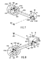
- Figure 7 shows how the gear 11 can be rotated.
- the bar B42 is rotated by the angle doubling mechanism D2, around the hinge point HP2. Because the rods B12, B22, B42, B32 form a parallelogram mechanism bar B32 will perform the same rotation as bar B42. By rotating bar B32 around MP the gear 11 will also get rotated due to which the bar B62 will also perform said rotation and the bar B72 will perform the same rotation around hinge point HP2.
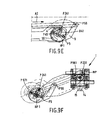
- Figures 9A-9F show in three steps the rotation of the tool T from a position in which the claws 14, 15 are direoted upwardly (figures 9A,9B) via a position in which the lever 5 is rotated over 45° whilst the bar B41 is rotated over 90° and the claws 14, 15 are directed to the right (figures 9C, 9D) to a position in which the lever 5 is rotated over 90° whilst the bar B41 is rotated over 180° and the claws 14, 15 of the tool T are directed downwardly (figures 9E, 9F). Since the gear 11 located in the tool T is rotated together with the tool T around the main pivot MP the bars of the second linkage mechanism M2 must perform the same rotation. This means that during the translation of the rod 6 in the direction indicated by arrow A2 to perform the rotation of the tool T also the rod 10 must be translated in the direction indicated by arrow A4 over the same distance.
- Figures 10A-10E show five different positions of the tool T and the claws 14, 15 located therein.
- the position as shown in figure 10B can be obtained by translating the slides 3, 7 and the rods 6, 10 over the same distance in the directions indicated by arrows A1-A4.
- the position as shown in figure 10D can be obtained by a controlled displacement of the rods 6, 10 and the slide 7 in the directions as indicated by arrows A2, A4, A3 respectively.
- the situation as shown in figure 10E can be obtained by displacing the rods 6, 10 along the same distance in the direction indicated by the arrows A2', A4'.
- gripping means 16 other manipulators or devices can be connected to the gear 11, like means for cutting, bending, soldering, engraving, measuring etc..
- the slides 3, 7 are movable along parallel linear paths. It is, however, also possible to move the slides for example perpendicular to each other whereby the same movements of the tool and gripper can be realised.
Landscapes
- Engineering & Computer Science (AREA)
- General Engineering & Computer Science (AREA)
- Mechanical Engineering (AREA)
- Robotics (AREA)
- Manipulator (AREA)
- Earth Drilling (AREA)
- Transmission Devices (AREA)
- Jib Cranes (AREA)
- Vehicle Body Suspensions (AREA)
- Joints Allowing Movement (AREA)
- Hand Tools For Fitting Together And Separating, Or Other Hand Tools (AREA)
- Pivots And Pivotal Connections (AREA)
- Supplying Of Containers To The Packaging Station (AREA)
Abstract
Description
Claims (7)
- Device comprising two linkage mechanisms (M1,M2) each having at least three bars (B11,B12,B21,B51,B31,B41,B61,B71,B22,B32,B42, B52,B62,B72) of which a first (B11, B12) and a second bar (B21, B51, B22, B52) with the same length extend parallel to each other and are pivotably interconnected by at least a third bar (B31, B22), the two frist and two third bars of both mechanisms are pivotably connected at a common main pivot (MP), hinge points (HP1,HP2) of the first bars lying away from the main pivot are independently movable along linear paths, the device is further provided with a tool (T) comprising the main pivot, the pivot points of the third and second bars of the first and second mechanism being connected to the tool and a part of the tool respectively characterized in that the first and second bars of each mechanism are pivotably connected by a fourth bar (B41, B42), lying parallel to and having the same length as the third bar the fourth bar is rotatable about the hinge point (HP1, HP2) of the first bar (B11, B12), whereby rotating the fourth bar of the first mechanism around the hinge point causes a rotation of the tool around the main pivot and rotating the fourth bar of the second mechanism around the hinge point causes rotation of the part of the tool around the main pivot.
- Device according to claim 1, characterized in that at least one linkage mechanism comprises a fifth bar (B51, B52) lying parallel to and having the same length as the first bar (B11,B12), the first and fifth bar are pivotably connected by a sixth and seventh bar lying parallel to each other and having the same length, the sixth bar is pivotably connected to the first bar at the main pivot point (Mp) and encloses an angle with the third bar.
- Device according to claim 1 or 2, characterized in that the fourth bar is pivotably connected to an angle doubling mechanism (D1, D2)
- Device according to claim 3, characterized in that said angle doubling mechanism (D1, D2) comprises a lever (5,9) which is at one end pivotable about a pivot and at the other end pivotably connected to a link (4, 8) which is pivotably being connected to the fourth arm at distance from the hinge point which is equal to the distance between said hinge point and the pivot of the lever, the lever having a length of twice said distance and the link having a length of √2 times said distance.
- Device according to one of the preceding claims, characterized in that said part of said tool comprises a gear (11).
- Device according to claim 5, characterized in that said tool comprises a gripping means (16) having two claws (14,15) which are each provided with rack (12,13), said racks are linearly driven by said gear into opposite directions.
- Device according to claim 6, characterized in that by rotating both fourth bars over the same angle a rotation of the tool is obtained, while by rotating the fourth bars over a different angle also an opening or closing of the gripping means is obtained.
Applications Claiming Priority (1)
| Application Number | Priority Date | Filing Date | Title |
|---|---|---|---|
| PCT/NL1998/000239 WO1999055496A1 (en) | 1998-04-29 | 1998-04-29 | Device comprising two parallel linkage mechanisms |
Publications (2)
| Publication Number | Publication Date |
|---|---|
| EP1075359A1 EP1075359A1 (en) | 2001-02-14 |
| EP1075359B1 true EP1075359B1 (en) | 2003-07-02 |
Family
ID=19866442
Family Applications (1)
| Application Number | Title | Priority Date | Filing Date |
|---|---|---|---|
| EP98920735A Expired - Lifetime EP1075359B1 (en) | 1998-04-29 | 1998-04-29 | Device comprising two parallel linkage mechanisms |
Country Status (13)
| Country | Link |
|---|---|
| US (1) | US6454513B1 (en) |
| EP (1) | EP1075359B1 (en) |
| JP (1) | JP2002512897A (en) |
| KR (1) | KR20010052275A (en) |
| CN (1) | CN1140388C (en) |
| AT (1) | ATE244112T1 (en) |
| AU (1) | AU7350998A (en) |
| BR (1) | BR9815851A (en) |
| CA (1) | CA2330386A1 (en) |
| DE (1) | DE69816133T2 (en) |
| HU (1) | HUP0102431A3 (en) |
| MX (1) | MXPA00010572A (en) |
| WO (1) | WO1999055496A1 (en) |
Cited By (1)
| Publication number | Priority date | Publication date | Assignee | Title |
|---|---|---|---|---|
| RU2453747C2 (en) * | 2009-02-27 | 2012-06-20 | Владимир Алексеевич Преображенский | Mechanism of piston travel acceleration |
Families Citing this family (18)
| Publication number | Priority date | Publication date | Assignee | Title |
|---|---|---|---|---|
| US8956421B2 (en) | 2007-02-06 | 2015-02-17 | Deka Products Limited Partnership | Dynamic support apparatus and system |
| US8074559B2 (en) | 2007-02-06 | 2011-12-13 | Deka Products Limited Partnership | Dynamic support apparatus and system |
| JP4515133B2 (en) * | 2004-04-02 | 2010-07-28 | 株式会社アルバック | Conveying apparatus, control method therefor, and vacuum processing apparatus |
| US8864845B2 (en) * | 2007-02-06 | 2014-10-21 | DEKA Limited Partnership | System for control of a prosthetic device |
| US8979943B2 (en) | 2007-02-06 | 2015-03-17 | Deka Products Limited Partnership | Arm prosthetic device |
| US8449624B2 (en) * | 2007-02-06 | 2013-05-28 | Deka Products Limited Partnership | Arm prosthetic device |
| US11779476B2 (en) | 2007-02-06 | 2023-10-10 | Deka Products Limited Partnership | Arm prosthetic device |
| US10426638B2 (en) | 2007-02-06 | 2019-10-01 | Deka Products Limited Partnership | Arm prosthetic device |
| US8870970B2 (en) * | 2007-02-06 | 2014-10-28 | Deka Products Limited Partnership | Dynamic support apparatus |
| WO2008098059A2 (en) * | 2007-02-06 | 2008-08-14 | Deka Integrated Solutions Corp. | Method and apparatus for control of a prosthetic |
| EP2114315B1 (en) * | 2007-02-06 | 2016-05-18 | DEKA Products Limited Partnership | Arm prosthetic device |
| US9381099B2 (en) | 2007-02-06 | 2016-07-05 | Deka Products Limited Partnership | Arm prosthetic device |
| US9114030B2 (en) | 2007-02-06 | 2015-08-25 | Deka Products Limited Partnership | System for control of a prosthetic device |
| US20100307278A1 (en) * | 2007-11-26 | 2010-12-09 | Motor Power Company S.R.L. | device for handling and/or performing work operations on objects |
| EP2419057B1 (en) * | 2009-04-13 | 2014-10-01 | DEKA Products Limited Partnership | System and apparatus for orientation control |
| US9844447B2 (en) | 2010-04-09 | 2017-12-19 | Deka Products Limited Partnership | System and apparatus for robotic device and methods of using thereof |
| CN110355737B (en) * | 2018-04-10 | 2022-06-10 | 苏州迈澜医疗科技有限公司 | Translation mechanism and multi-degree-of-freedom guide mechanism with same |
| DE102019001402B3 (en) | 2019-02-27 | 2020-06-18 | Mrc Systems Gmbh | Handheld or external robotic system for spatial guidance of an end effector |
Family Cites Families (5)
| Publication number | Priority date | Publication date | Assignee | Title |
|---|---|---|---|---|
| FR1458379A (en) | 1965-08-31 | 1966-03-04 | Commissariat Energie Atomique | Handling device |
| US4723460A (en) * | 1984-04-12 | 1988-02-09 | Rosheim Mark E | Robot wrist actuator |
| US4687400A (en) | 1984-09-07 | 1987-08-18 | Metals, Ltd. | Device for moving objects in a closed container |
| US5190333A (en) * | 1991-04-08 | 1993-03-02 | Minichan Richard L | Gripper deploying and inverting linkage |
| US5699695A (en) * | 1996-05-01 | 1997-12-23 | Virginia Tech Intellectual Properties, Inc. | Spatial, parallel-architecture robotic carpal wrist |
-
1998
- 1998-04-29 MX MXPA00010572A patent/MXPA00010572A/en not_active IP Right Cessation
- 1998-04-29 AU AU73509/98A patent/AU7350998A/en not_active Abandoned
- 1998-04-29 EP EP98920735A patent/EP1075359B1/en not_active Expired - Lifetime
- 1998-04-29 US US09/674,243 patent/US6454513B1/en not_active Expired - Fee Related
- 1998-04-29 CN CNB988139987A patent/CN1140388C/en not_active Expired - Fee Related
- 1998-04-29 CA CA002330386A patent/CA2330386A1/en not_active Abandoned
- 1998-04-29 KR KR1020007012013A patent/KR20010052275A/en not_active Abandoned
- 1998-04-29 DE DE69816133T patent/DE69816133T2/en not_active Expired - Fee Related
- 1998-04-29 WO PCT/NL1998/000239 patent/WO1999055496A1/en not_active Ceased
- 1998-04-29 AT AT98920735T patent/ATE244112T1/en not_active IP Right Cessation
- 1998-04-29 HU HU0102431A patent/HUP0102431A3/en unknown
- 1998-04-29 BR BR9815851-1A patent/BR9815851A/en active Search and Examination
- 1998-04-29 JP JP2000545678A patent/JP2002512897A/en active Pending
Cited By (1)
| Publication number | Priority date | Publication date | Assignee | Title |
|---|---|---|---|---|
| RU2453747C2 (en) * | 2009-02-27 | 2012-06-20 | Владимир Алексеевич Преображенский | Mechanism of piston travel acceleration |
Also Published As
| Publication number | Publication date |
|---|---|
| AU7350998A (en) | 1999-11-16 |
| CN1292743A (en) | 2001-04-25 |
| CN1140388C (en) | 2004-03-03 |
| MXPA00010572A (en) | 2002-04-24 |
| HUP0102431A3 (en) | 2001-12-28 |
| JP2002512897A (en) | 2002-05-08 |
| ATE244112T1 (en) | 2003-07-15 |
| BR9815851A (en) | 2000-12-26 |
| EP1075359A1 (en) | 2001-02-14 |
| KR20010052275A (en) | 2001-06-25 |
| WO1999055496A1 (en) | 1999-11-04 |
| DE69816133D1 (en) | 2003-08-07 |
| CA2330386A1 (en) | 1999-11-04 |
| US6454513B1 (en) | 2002-09-24 |
| HUP0102431A2 (en) | 2001-11-28 |
| DE69816133T2 (en) | 2004-06-03 |
Similar Documents
| Publication | Publication Date | Title |
|---|---|---|
| EP1075359A1 (en) | Device comprising two parallel linkage mechanisms | |
| EP1684950B1 (en) | Parallel kinematics mechanism with a concentric spherical joint | |
| CA2176899C (en) | Mechanism for control of position and orientation in three dimensions | |
| JP7527020B2 (en) | Parallel mechanisms with kinematically redundant actuation. | |
| US20080262653A1 (en) | Parallel Robot Comprising Assembly for Moving a Mobile Element Composed of Two Subassemblies | |
| EP1084802A2 (en) | Four-degree-of-freedom parallel robot | |
| KR102842610B1 (en) | Parallel motion machine with various tool directions | |
| CN102107431A (en) | Parallel robot | |
| KR20240111805A (en) | Industrial robot arm | |
| WO2007062505A1 (en) | Planar parallel mechanism and method | |
| US5107719A (en) | Adjustable robotic mechanism | |
| US20030151379A1 (en) | Parallel control arm with two branches | |
| US12134187B2 (en) | Agile robot arm for positioning a tool with controlled orientation | |
| US20040013509A1 (en) | Parallel kinematics mechanism with a concentric spherical joint | |
| US4717303A (en) | Joint mechanism for manipulators | |
| JP2021133444A (en) | Robot hand and gripping system | |
| RU2245241C2 (en) | Three-dimensional controlled actuating mechanism of robot | |
| GB2173472A (en) | Manipulator | |
| EP1052071A2 (en) | High-speed industrial handler | |
| JPH07276270A (en) | Parallel link type articulated robot | |
| CA3149563C (en) | A parallel-kinematic machine with versatile tool orientation | |
| SU1341017A1 (en) | Manipulator | |
| CN114786884A (en) | Multi-degree-of-freedom parallel mechanism | |
| SU1445948A1 (en) | Device frp controlling manipulator | |
| CZ29702U1 (en) | Device to control spherical motion of a body |
Legal Events
| Date | Code | Title | Description |
|---|---|---|---|
| PUAI | Public reference made under article 153(3) epc to a published international application that has entered the european phase |
Free format text: ORIGINAL CODE: 0009012 |
|
| 17P | Request for examination filed |
Effective date: 20001009 |
|
| AK | Designated contracting states |
Kind code of ref document: A1 Designated state(s): AT BE DE FI FR GB IE IT NL SE |
|
| GRAH | Despatch of communication of intention to grant a patent |
Free format text: ORIGINAL CODE: EPIDOS IGRA |
|
| GRAH | Despatch of communication of intention to grant a patent |
Free format text: ORIGINAL CODE: EPIDOS IGRA |
|
| GRAA | (expected) grant |
Free format text: ORIGINAL CODE: 0009210 |
|
| AK | Designated contracting states |
Designated state(s): AT BE DE FI FR GB IE IT NL SE |
|
| PG25 | Lapsed in a contracting state [announced via postgrant information from national office to epo] |
Ref country code: NL Free format text: LAPSE BECAUSE OF FAILURE TO SUBMIT A TRANSLATION OF THE DESCRIPTION OR TO PAY THE FEE WITHIN THE PRESCRIBED TIME-LIMIT Effective date: 20030702 Ref country code: IT Free format text: LAPSE BECAUSE OF FAILURE TO SUBMIT A TRANSLATION OF THE DESCRIPTION OR TO PAY THE FEE WITHIN THE PRE;WARNING: LAPSES OF ITALIAN PATENTS WITH EFFECTIVE DATE BEFORE 2007 MAY HAVE OCCURRED AT ANY TIME BEFORE 2007. THE CORRECT EFFECTIVE DATE MAY BE DIFFERENT FROM THE ONE RECORDED.SCRIBED TIME-LIMIT Effective date: 20030702 Ref country code: FI Free format text: LAPSE BECAUSE OF FAILURE TO SUBMIT A TRANSLATION OF THE DESCRIPTION OR TO PAY THE FEE WITHIN THE PRESCRIBED TIME-LIMIT Effective date: 20030702 Ref country code: BE Free format text: LAPSE BECAUSE OF FAILURE TO SUBMIT A TRANSLATION OF THE DESCRIPTION OR TO PAY THE FEE WITHIN THE PRESCRIBED TIME-LIMIT Effective date: 20030702 Ref country code: AT Free format text: LAPSE BECAUSE OF FAILURE TO SUBMIT A TRANSLATION OF THE DESCRIPTION OR TO PAY THE FEE WITHIN THE PRESCRIBED TIME-LIMIT Effective date: 20030702 |
|
| REG | Reference to a national code |
Ref country code: GB Ref legal event code: FG4D |
|
| REG | Reference to a national code |
Ref country code: IE Ref legal event code: FG4D |
|
| REF | Corresponds to: |
Ref document number: 69816133 Country of ref document: DE Date of ref document: 20030807 Kind code of ref document: P |
|
| PG25 | Lapsed in a contracting state [announced via postgrant information from national office to epo] |
Ref country code: SE Free format text: LAPSE BECAUSE OF FAILURE TO SUBMIT A TRANSLATION OF THE DESCRIPTION OR TO PAY THE FEE WITHIN THE PRESCRIBED TIME-LIMIT Effective date: 20031002 |
|
| NLV1 | Nl: lapsed or annulled due to failure to fulfill the requirements of art. 29p and 29m of the patents act | ||
| ET | Fr: translation filed | ||
| PG25 | Lapsed in a contracting state [announced via postgrant information from national office to epo] |
Ref country code: IE Free format text: LAPSE BECAUSE OF NON-PAYMENT OF DUE FEES Effective date: 20040429 |
|
| PLBE | No opposition filed within time limit |
Free format text: ORIGINAL CODE: 0009261 |
|
| STAA | Information on the status of an ep patent application or granted ep patent |
Free format text: STATUS: NO OPPOSITION FILED WITHIN TIME LIMIT |
|
| 26N | No opposition filed |
Effective date: 20040405 |
|
| REG | Reference to a national code |
Ref country code: IE Ref legal event code: MM4A |
|
| PGFP | Annual fee paid to national office [announced via postgrant information from national office to epo] |
Ref country code: FR Payment date: 20050315 Year of fee payment: 8 |
|
| PGFP | Annual fee paid to national office [announced via postgrant information from national office to epo] |
Ref country code: GB Payment date: 20050427 Year of fee payment: 8 |
|
| PGFP | Annual fee paid to national office [announced via postgrant information from national office to epo] |
Ref country code: DE Payment date: 20050628 Year of fee payment: 8 |
|
| PG25 | Lapsed in a contracting state [announced via postgrant information from national office to epo] |
Ref country code: GB Free format text: LAPSE BECAUSE OF NON-PAYMENT OF DUE FEES Effective date: 20060429 |
|
| PG25 | Lapsed in a contracting state [announced via postgrant information from national office to epo] |
Ref country code: DE Free format text: LAPSE BECAUSE OF NON-PAYMENT OF DUE FEES Effective date: 20061101 |
|
| GBPC | Gb: european patent ceased through non-payment of renewal fee |
Effective date: 20060429 |
|
| REG | Reference to a national code |
Ref country code: FR Ref legal event code: ST Effective date: 20061230 |
|
| PG25 | Lapsed in a contracting state [announced via postgrant information from national office to epo] |
Ref country code: FR Free format text: LAPSE BECAUSE OF NON-PAYMENT OF DUE FEES Effective date: 20060502 |