EP1075148A2 - Error resistant video coding using reversible variable length codes (RVLCs) - Google Patents
Error resistant video coding using reversible variable length codes (RVLCs) Download PDFInfo
- Publication number
- EP1075148A2 EP1075148A2 EP00202719A EP00202719A EP1075148A2 EP 1075148 A2 EP1075148 A2 EP 1075148A2 EP 00202719 A EP00202719 A EP 00202719A EP 00202719 A EP00202719 A EP 00202719A EP 1075148 A2 EP1075148 A2 EP 1075148A2
- Authority
- EP
- European Patent Office
- Prior art keywords
- motion
- data
- error
- video
- motion vectors
- Prior art date
- Legal status (The legal status is an assumption and is not a legal conclusion. Google has not performed a legal analysis and makes no representation as to the accuracy of the status listed.)
- Withdrawn
Links
Images


Classifications
-
- H—ELECTRICITY
- H04—ELECTRIC COMMUNICATION TECHNIQUE
- H04N—PICTORIAL COMMUNICATION, e.g. TELEVISION
- H04N19/00—Methods or arrangements for coding, decoding, compressing or decompressing digital video signals
-
- H—ELECTRICITY
- H04—ELECTRIC COMMUNICATION TECHNIQUE
- H04N—PICTORIAL COMMUNICATION, e.g. TELEVISION
- H04N19/00—Methods or arrangements for coding, decoding, compressing or decompressing digital video signals
- H04N19/50—Methods or arrangements for coding, decoding, compressing or decompressing digital video signals using predictive coding
- H04N19/503—Methods or arrangements for coding, decoding, compressing or decompressing digital video signals using predictive coding involving temporal prediction
- H04N19/51—Motion estimation or motion compensation
- H04N19/513—Processing of motion vectors
- H04N19/517—Processing of motion vectors by encoding
-
- H—ELECTRICITY
- H04—ELECTRIC COMMUNICATION TECHNIQUE
- H04N—PICTORIAL COMMUNICATION, e.g. TELEVISION
- H04N19/00—Methods or arrangements for coding, decoding, compressing or decompressing digital video signals
- H04N19/65—Methods or arrangements for coding, decoding, compressing or decompressing digital video signals using error resilience
- H04N19/66—Methods or arrangements for coding, decoding, compressing or decompressing digital video signals using error resilience involving data partitioning, i.e. separation of data into packets or partitions according to importance
-
- H—ELECTRICITY
- H04—ELECTRIC COMMUNICATION TECHNIQUE
- H04N—PICTORIAL COMMUNICATION, e.g. TELEVISION
- H04N19/00—Methods or arrangements for coding, decoding, compressing or decompressing digital video signals
- H04N19/65—Methods or arrangements for coding, decoding, compressing or decompressing digital video signals using error resilience
- H04N19/68—Methods or arrangements for coding, decoding, compressing or decompressing digital video signals using error resilience involving the insertion of resynchronisation markers into the bitstream
-
- H—ELECTRICITY
- H04—ELECTRIC COMMUNICATION TECHNIQUE
- H04N—PICTORIAL COMMUNICATION, e.g. TELEVISION
- H04N19/00—Methods or arrangements for coding, decoding, compressing or decompressing digital video signals
- H04N19/65—Methods or arrangements for coding, decoding, compressing or decompressing digital video signals using error resilience
- H04N19/69—Methods or arrangements for coding, decoding, compressing or decompressing digital video signals using error resilience involving reversible variable length codes [RVLC]
-
- H—ELECTRICITY
- H04—ELECTRIC COMMUNICATION TECHNIQUE
- H04N—PICTORIAL COMMUNICATION, e.g. TELEVISION
- H04N19/00—Methods or arrangements for coding, decoding, compressing or decompressing digital video signals
- H04N19/85—Methods or arrangements for coding, decoding, compressing or decompressing digital video signals using pre-processing or post-processing specially adapted for video compression
- H04N19/89—Methods or arrangements for coding, decoding, compressing or decompressing digital video signals using pre-processing or post-processing specially adapted for video compression involving methods or arrangements for detection of transmission errors at the decoder
-
- H—ELECTRICITY
- H04—ELECTRIC COMMUNICATION TECHNIQUE
- H04N—PICTORIAL COMMUNICATION, e.g. TELEVISION
- H04N19/00—Methods or arrangements for coding, decoding, compressing or decompressing digital video signals
- H04N19/70—Methods or arrangements for coding, decoding, compressing or decompressing digital video signals characterised by syntax aspects related to video coding, e.g. related to compression standards
Definitions
- the present application relates generally to the field of information encoding for transmission over noisy channels and storage, and more particularly to error resilient encoding.
- ARQ Automatic Retransmission Request
- FEC Forward Error Correction
- motion compensation methods encode only (macro)block motion vectors and the corresponding quantized residuals (texture); and variable length coding (VLC) of the motion vectors and residual increases coding efficiency.
- VLC variable length coding
- variable length coding often are highly susceptible to transmission channel errors and a decoder easily loses synchronization with the encoder when uncorrectable errors arise.
- the predictive coding methods, such as motion compensation make matters much worse because the errors in one video frame quickly propagate across the entire video sequence and rapidly degrade the decoded video quality.
- the typical approach of such block-based video compression methods to uncorrectable errors includes the steps of error detection (e.g., out-of-range motion vectors, invalid VLC table entry, or invalid number of residuals in a block), resynchronization of the decoder with the encoder, and error concealment by repetition of previously transmitted correct data in place of the uncorrectable data.
- error detection e.g., out-of-range motion vectors, invalid VLC table entry, or invalid number of residuals in a block
- error concealment by repetition of previously transmitted correct data in place of the uncorrectable data e.g., out-of-range motion vectors, invalid VLC table entry, or invalid number of residuals in a block
- error detection e.g., out-of-range motion vectors, invalid VLC table entry, or invalid number of residuals in a block
- resynchronization of the decoder with the encoder e.g., resynchronization of the decoder with the encoder
- error concealment by repetition of previously transmitted correct
- VLC Variable Length Code
- Golomb-Rice codes (S.W.Golomb, "Run-length encodings," IEEE Trans. Inf. Theory, vol. IT-12, pp.399-401, July 1966 and R.F.Rice, "some practical universal noiseless coding techniques," Tech. Rep. JPL-79-22, Jet Propulsion Laboratory, Pasadena, CA, march 1979) have been applied to lossless image compression; see M.J.Weinberger, G.Seroussi, and G.Sapiro, "LOCO-I: A low complexity, context based lossless image compression algorithm," Proc 1996 IEEE Data Comp. Conf., Snowbird, UT, pp.140-149, April, 1996.
- Video compression and decompression methods may be implemented on special integrated circuits or on programmable digital signal processors or microprocessors.
- the present invention uses reversible variable length codes (RVLC) to encode motion vectors to help alleviate the error problems in motion compensated compressed video such as MPEG.
- RVLC reversible variable length codes
- These RVLC have an interleaved structure of a coarse code (indicating a range of values) and additional bits (indicating a value with the range of values); the coarse code provides the reversibility.
- Preferred embodiments include data partitioning with a resynchronization word between motion vector data and texture (residual) data for the macroblocks in a data packet; this permits simple differential motion vector encoding by using the immediately prior motion vector as a predictor.
- Enhanced error concealment properties for motion compensated compression can be achieved by using data partitioning.
- a "video packet" to consist of the data between two consecutive resynchronization markers.
- the motion data and the texture (DCT) data within each of the video packets are separately encoded in the bitstream.
- Another resynchronization word (Motion Resync. Word) is imbedded between the motion data and the DCT data to signal the end of the motion data and the beginning of the DCT data.
- This data partitioning allows the decoder to use the motion data even if the DCT data is corrupted by undetectable errors. This provides advantages including partial recovery over uncorrectable error in a packet of compressed video data with little additional overhead.
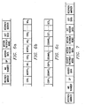
- Figure 6a shows the fields between two resynchronization markers and Figures 6b-c illustrate the motion data field and the texture data field in more detail by an example.
- the first field (“Resynch Marker”) is a resynchronization marker
- the second field (“MB No.”) is the number in the frame of the first macroblock (16 x 16 block of pixels) in the video packet
- the third field (“QP") is the default quantization parameter used to quantize the texture data (DCT coefficients) in the video packet
- the fourth field (“Motion Data”) is the motion data
- the fifth field (“Motion Resynch Word”) is the resynchronization marker between the motion data and the texture data
- the sixth field (“DCT Data”) is the texture data
- the last field (“Resynch Marker”) is the ending resynchronization marker.
- the resynchronization marker is taken to have 23 successive 0s, and that these resynchronization words can be created by
- Figure 6b shows the motion data field consisting of a COD field, an MCBPC field, and an MV field for each the macroblocks in the packet.
- the MCBPC field indicates (1) the mode of the macroblock (and (2) which of the chrominance blocks in the macroblock are coded and which are skipped: the mode indicates whether there the current macroblock is coded INTRA (no motion compensation), INTER (motion compensated with one 16 x 16 motion vector), or INTER4V (motion compensated with four 8 x 8 motion vectors).
- the MV field is the actual motion vector data; either one vector or four vectors. Again, if COD indicates that the macroblock is not coded, then the MV field is not present.
- Figure 6c shows the texture (DCT Data) field as consisting of a CBPY field and a DQUANT field for each of the macroblocks followed by the DCT data for each of the macroblocks.
- the CBPY field indicates which of the luminance blocks of the macroblock are coded and which are skipped.
- the DQUANT field indicates the differential increment to the default quantizer value (QP) to compute the quantization value for the macroblock.
- the DCT fields are the run length encoded quantized DCT coefficient values of the macroblock.
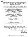
- the preferred embodiment syntax of the bitstream within a video packet with headers and data using RVLC is shownb in Figure 7.
- the Resynch Marker, MB No., QP, and Motion Resynchr Word fields are as in Figure 6a;
- the Motion Vector Data field consists of the motion vector data MV1, MV2, ... MVn as in Figure 6b;
- the DCT Header Data field consists of the CBPY1, DQUANT1, ..., CBPYn, DQUANTn of Figure 6c;
- the DCT Data field consists of the DCT1, DCT2, ..., DCTn also of Figure 6c.
- the Header Data field consists of one RVLC entry for the combined COD and MCBPC data for each macroblock (see Figure 6b), and the Header Resynchronization Word is a uniquely decoded word similar to the Motion Resynchronization Word.
- sequences of RVLC entries occur in the Header Data, Motion Vector Data, DCT Header Data, and DCT Data fields; of course each field has its own RVLC table as detailed below.
- the decoder seeks the next resynchronization word, (either Header Resync. Word or Motion Resync. Word or the Resync. Marker). It then decodes the RVLC data backwards. Now, one of the four possible cases shown below can occur and the decoder decides to discard the appropriate part of the bitstream shown shaded in the figures below.
- the decoder also flags the bitstream as being in error if the forward decoded and the backward decoded data do not match despite both directions being decoded without apparent errors.
- the decoder is able to salvage a significantly larger part of the bitstream that is not in error.
- the preferred embodiment parameterized RVLCs have identical code length distributions to previously known, non-reversible VLCs that are known to be near-optimal for probability density functions (pdfs) that occur in coding of image data.
- the RVLCs presented are parameterized to allow them to be adapted to match a wide range of pdfs, and enable the advantages of two-way decoding while retaining the efficiency of traditional (non-reversible) variable length codes.
- Golomb-Rice codes are nearly optimal for coding of exponentially distributed non-negative integers, and describe an integer n in terms of a quotient and a remainder.
- the divisor is often chosen to be a power of 2, i.e., 2 k , and is parameterized by k.
- the quotient can be arbitrarily large and is expressed using a unary representation; the remainder is bounded by the range [0,2 k-1 ) and is expressed in binary form using k bits.
- Exp-Golomb codes can be parameterized according to k, the number of bits in the suffix of the codeword.
- the even-indexed bits are allowed to vary arbitrarily, allowing 2 (l-1)/2 possible prefixes of length l, where l is odd.
- each prefix is concatenated with the 2 k distinct suffixes of length k.
- Table 2 gives an RVLC constructed according to these rules. Again, it is clear that the length distribution of the RVLC is identical to that of the corresponding reversible code.
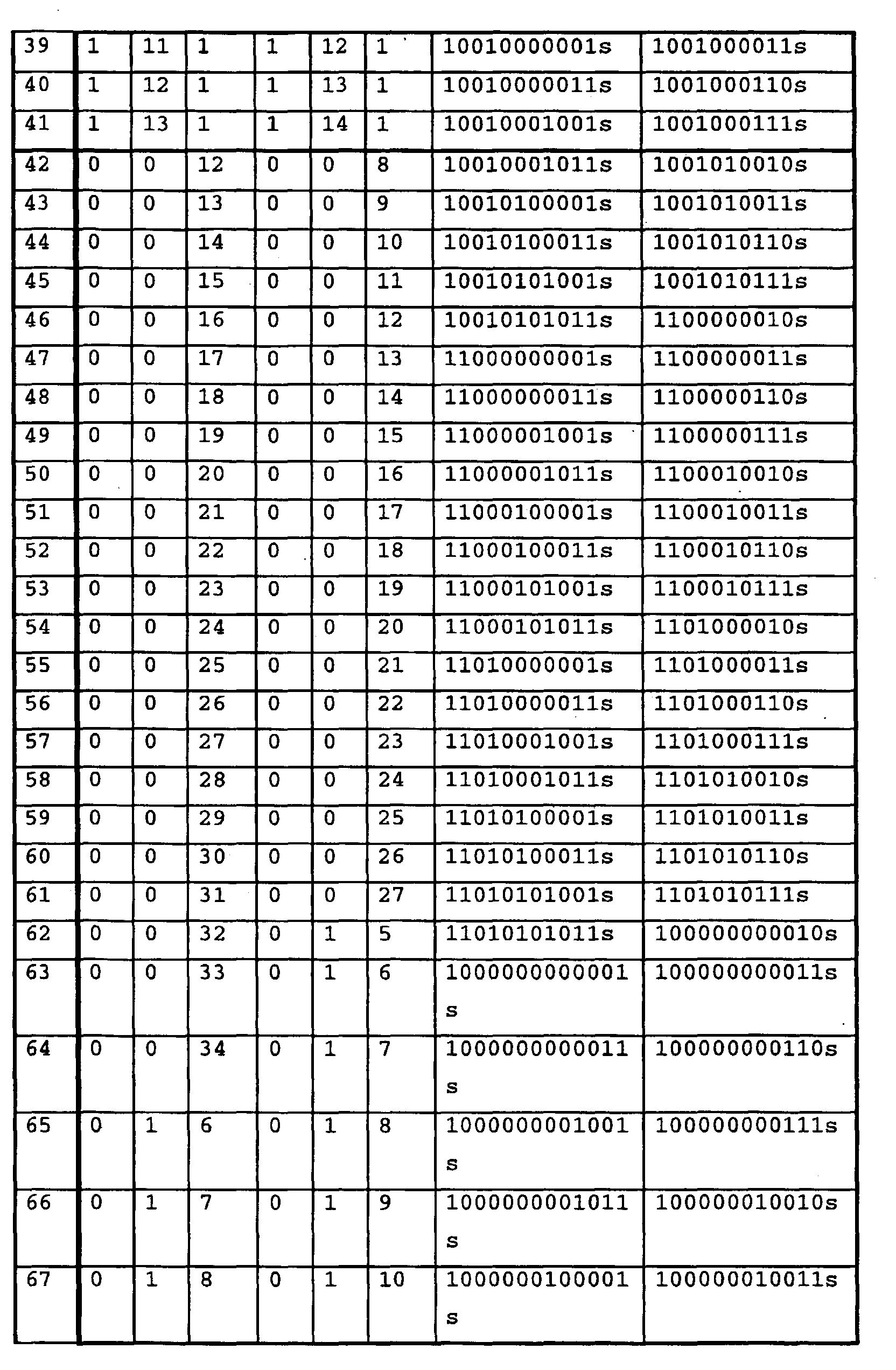
- RVLCs were designed for each of (1) Header Data (COD + MCBPC) (for both INTRA and INTER frames), (2) Motion Vector Data, (3) INTRA frame DCT Data, and (4) INTER frame DCT Data.
- COD + MCBPC Header Data
- Motion Vector Data Motion Vector Data
- INTRA frame DCT Data INTRA frame DCT Data
- INTER frame DCT Data Use two classes of RVLCs.
- the first class of RVLC is used to code the header information (COD + MCBPC).
- One RVLC is used for the INTRA frames and one is used for the INTER frames.
- the second class is an RVLC, which can be parameterized by a parameter k, will be used for the entropy coding of quantized DCT coefficients and also the coding of the motion vector data.
- FLC fixed length code
- the foregoing preferred embodiment used preferred embodiment RVLCs within a preferred embodiment syntax in which the motion data was partitioned into header data and motion vector data and separated by a Header Resynchronization Word.
- the preferred embodiment RVLCs can also be used with the data partitioning as in Figure 6a by using the codes of Table 7 for the DCT data (DCT1, DCG2, ... DCTn) of Figure 6c.
- an RVLC can be used to code the CBPY plus DQUANT fields.
- An alternative preferred embodiment uses the RVLC of Table 8 for the motion vector data without also using the separated header data and header resynchronization word.
- RVLCs can be made in analogous fashions.
- Tables 9-11 are other versions of foregoing Tables 4 and 7-8.
- RVLCs and bitstream syntax also extends to object based compression by just including the object shape data in a field (typically preceding the motion data) and optionally with a Shape Resynchronization Word to separate shape data from motion data.
- a further preferred embodiment also uses reversible variable length codes with the more important motion vector data separated from the texture data plus adds a new syntax element which conveys the current status of motion vector predictor (called the motion vector predictor status). This is useful for the forward and backward decoding to verify if motion vectors are correctly decoded.
- the number of motion vector predictor status elements depends upon channel conditions: for high error rates more elements are used.
- FIG. 8 shows the structure of the inter video packet in non-intra VOPs; note that coding of intra video packets can be the same as the MPEG-4 VM7.0.
- Packet headers are inserted into the compressed data at the beginning of each packet.
- the packet header consists of a unique 17-bit resynchronization marker ("Resync. Marker” in Figure 8 and which may be 0000 0000 0000 0000 1) followed by N bits indicating the current macroblock number ("MB No.” where the number of macroblocks in the VOP is at most 2 N ) and 5 bits for the quantization parameter ("QP"), and the header extension code. All syntax elements other than motion data and texture header may be the same as in VM7.0.
- Figure 9 illustrates the structure of the motion data field
- Figure 10 shows the assembly of the variable length codes for the motion vectors with the "motion_type_flag" distinguishing the 16x16 macroblock motion compensation from the four 8x8 block motion compensation.
- the last macroblock in a video packet will not be coded as "skipped macroblock”.
- Table 12 shows the mv_vlc coding.
- each mv_vlc is composed of two parts: coarse code and additional code. The coarse code appears in the even-numbered bits and is reversible such as "0", "11", "101", while the additional code is the sequence of odd-numbered bits. In this way, mv_vlc can be uniquely constituted.
- the coarse code is not only a marker enabling two-way decoding, but also a meaningful code which conveys rough information, i.e., range of the value to be expressed by the VLC.
- the syntax of motion vector coding is as follows: where mv_vlc(horizontal) and mv_vlc(vertical) are taken from Table 12 and may have from 1 to 27 bits and motion_type_flag is one bit as noted in Figure 10.
- the syntax of the motion data is as follows: where first MB_Inc is actually NB_Inc+1, MVs_Motion type distinguishes between 16x16 motion compensation and four 8x8 motion compensation as in Figure 10, MB_Inc has 1 to 13 bits, and motion_marker is the 17 bits "1100 0000 0000 0000 1".
- MB_Inc replaces COD used in VM7.0.
- MB_Inc tells how many macroblocks are skipped, i.e., incremented, from the previously coded macroblock.
- Table 13 show the MB_Inc VLC codes. Note that the first MB_Inc in a packet (distinguished as "first_MB_Inc") tells which macroblock is coded first in a packet.
- the first_MB_Inc is also coded per Table 13, so its value means that actual increment plus one on the assumption that the previously coded macroblock corresponds to the one specified by macroblock_number field in the packet. (MB-No.).
- the "MV predictor status" represents the value of horizontal and vertical components of MV predictors.
- the value coded in the MV predictor of the macroblock immediately preceding the event, i.e., MB_Inc "000".
- At least one MV status just before the motion_marker should be inserted to allow decoding in both directions and MV predictor status shall be put in as often as required to enhance the error robustness.
- Figure 11 illustrates the rules for predictive coding of motion vectors: only one MV predictor for each horizontal and vertical component is used; MV predictor is not reset at the skipped macroblock; MV of 16x16 motion compensation is coded also for intra macroblock for error concealment purposes. This MV is used to obtain motion compensation signals when the texture data cannot be decoded. The motion vector difference MVD(0,0) is coded for this mode at the core experiments.
- macroblock_type (MB_type) is as follows: where MCBPC has 1 to 8 bits as in Table 14, CBPY has 2 to 6 bits as in VM7.0, and dquant has 2 bits as in VM7.0.
- the decoder resynchronizes at the next resynchronization point, either resynch marker or common start code (i.e., 23-bit "0" + “1"), but the one encountered first in the bitstream:
- MBA[k] denote the number of the first macroblock in the current packet
- MBA[k+1] denote the number of the first macroblock in the next packet.
- An additional check can be performed when, no error is detected in either the motion or the texture parts of the packet and the next resynchronization marker is correctly found. In this case check if MBA[k+1]-MBA[k] is equal to NMB. If not, discard the data in the next video packet (packet corresponding to MBA[k+1]).
- the decoder when an error is detected in the motion data section, the decoder discards entire packet and resynchronizes to the next successfully read resync marker or VOP start code. Whilst the decoder of the proposed method conducts MV recovery as described in the following section and do motion compensation suing recovered MVs.
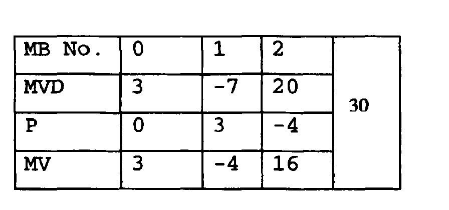
- MVDs and P[0] which is assumed to be 0 at the beginning of a packet can reconstruct MVs in forward decoding, while MV[], which should be embedded as predictor status, and MVDs can also restore the MVs in backward decoding.
- these MVs are coded as follows.
- the single entry columns denotes MV predictor status.
- the decoder consistent with the preferred embodiment works in three steps: error detection, resynchronization, error recovery and error concealment. These steps are depicted one by one assuming a bit error takes place at the same location as in above example as follows.
- Step 1 Errors can be detected when the MV predictor in actual decoding differs from MV predictor status.
- the MV predictor in actual decoding is 16 while MV predictor status represents 30. Note that errors can also be detected when an illegal VLC codeword is encountered.
- Step 2 Once an error has been detected the decoder seeks resynchronization point by searching for a motion marker.
- Step 3 The backward decoding commences at MV predictor status immediately preceding motion marker. This process last until one of the two events occurs; (1) MV predictor status differs from MV predictor in backward decoding (2) the process reaches the MB where an error has been detected. (This MV shall not be processed.) When the backward decoding terminates, the data which has been recovered are restored as correct information.
- Step 4 The data which has not be confirmed by MV predictor status in the forward decoding should be decontaminated. In this particular implementation, those MVs are reset to 0. Note this process may be optimized based on further investigation.
- the texture data which follows the motion data should be dealt with accordingly.
- the prediction error signals corresponding to the MBs processed by error concealment shall be discarded. However, if a MB is intra coded and is correctly decoded, the MB is represented as intra MB even if the motion data for that MB is successfully restored.
Landscapes
- Engineering & Computer Science (AREA)
- Multimedia (AREA)
- Signal Processing (AREA)
- Compression Or Coding Systems Of Tv Signals (AREA)
- Compression, Expansion, Code Conversion, And Decoders (AREA)
- Error Detection And Correction (AREA)
Abstract
Description
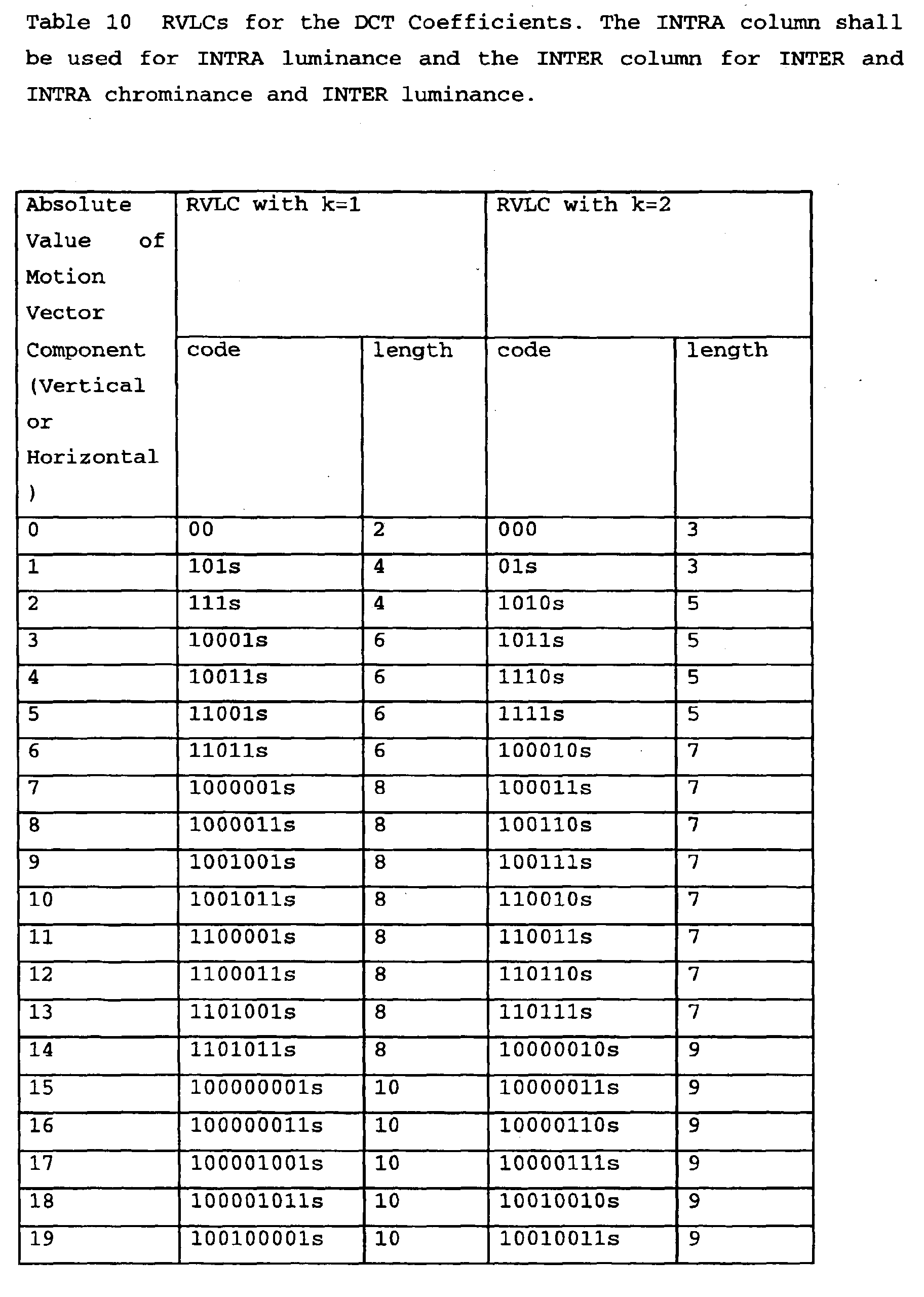
Table 2 below gives Golomb-Rice codes for the first several integers for two choices of the parameter k.
Table 2 illustrates the exp-Golomb code for k=1,2. It is possible, though less straightforward, to construct a reversible code that has the same length distribution as an exp-Golomb code. To do this again impose the constraint that the first and last bits of the prefix be "1". As before, the prefix of length one is set to "0". Require that all odd-indexed bits in the prefix, with the exception of the first and last bit, be "0". For example, in all prefixes of
Table 2 gives an RVLC constructed according to these rules. Again, it is clear that the length distribution of the RVLC is identical to that of the corresponding reversible code.


Claims (10)
- Motion compensated video of the type with packets including macroblock motion vectors and texture data, comprising:motion vectors encoded with codewords including a reversible coarse code plus interleaved additional code bits.
- The video of claim 1, wherein:the motion vector components are differentially encoded with a predictor the preceding motion vector components.
- The video of claim 2, wherein:the motion vector component codewords are as listed in table 12.
- The video of any of claims 1 to 3, wherein:the coarse code indicates a range of values; andthe additional bits indicate a value with the range of values.
- A decoder for motion compensated video of the type with packets including macroblock motion vectors and texture data, comprising:a decoder operative to detect motion vectors encoded with codewords including a reversible coarse code plus interleaved additional code bits.
- An encoder for motion compensated video of the type with packets including macroblock motion vectors and texture data, comprising:an encoder operative to encode motion vectors with codewords including a reversible coarse code plus interleaved additional code bits.
- A method of motion compensating video of the type with packets including macroblock motion vectors and texture data, comprising:encoding motion vectors with codewords including a reversible coarse code plus interleaved additional code bits.
- The method of Claim 7 further comprising:detecting motion vectors encoded with codewords including areversible coarse code plus interleaved additional code bits.
- The method of claim 7 or claim 8, further comprising:differentially encoding motion vector components with a predictor.
- The method of claim 9, wherein the step of differentially encoding motion vector components comprises:differentially encoding motion vector component with codewords listed in table 12.
Applications Claiming Priority (2)
| Application Number | Priority Date | Filing Date | Title |
|---|---|---|---|
| US14688899P | 1999-08-02 | 1999-08-02 | |
| US146888P | 1999-08-02 |
Publications (2)
| Publication Number | Publication Date |
|---|---|
| EP1075148A2 true EP1075148A2 (en) | 2001-02-07 |
| EP1075148A3 EP1075148A3 (en) | 2005-08-24 |
Family
ID=22519434
Family Applications (1)
| Application Number | Title | Priority Date | Filing Date |
|---|---|---|---|
| EP00202719A Withdrawn EP1075148A3 (en) | 1999-08-02 | 2000-07-31 | Error resistant video coding using reversible variable length codes (RVLCs) |
Country Status (3)
| Country | Link |
|---|---|
| EP (1) | EP1075148A3 (en) |
| JP (1) | JP2001103475A (en) |
| KR (1) | KR20010030046A (en) |
Cited By (3)
| Publication number | Priority date | Publication date | Assignee | Title |
|---|---|---|---|---|
| WO2003013147A1 (en) * | 2001-08-02 | 2003-02-13 | Koninklijke Philips Electronics N.V. | Video coding method |
| WO2003071777A3 (en) * | 2002-02-21 | 2004-02-26 | British Telecomm | Video processing |
| RU2580054C2 (en) * | 2011-07-01 | 2016-04-10 | Квэлкомм Инкорпорейтед | Video coding using adaptive motion vector resolution |
Families Citing this family (1)
| Publication number | Priority date | Publication date | Assignee | Title |
|---|---|---|---|---|
| US7630563B2 (en) * | 2001-07-19 | 2009-12-08 | Qualcomm Incorporated | System and method for decoding digital image and audio data in a lossless manner |
Family Cites Families (3)
| Publication number | Priority date | Publication date | Assignee | Title |
|---|---|---|---|---|
| EP1802129A3 (en) * | 1995-03-15 | 2008-10-22 | Kabushiki Kaisha Toshiba | Moving picture coding and/or decoding systems |
| EP0861001B1 (en) * | 1997-02-07 | 2012-05-23 | Texas Instruments Incorporated | Error resilient video encoding |
| CN1294759C (en) * | 1997-12-01 | 2007-01-10 | 三星电子株式会社 | Video code method |
-
2000
- 2000-07-31 EP EP00202719A patent/EP1075148A3/en not_active Withdrawn
- 2000-08-02 KR KR1020000044727A patent/KR20010030046A/en not_active Withdrawn
- 2000-08-02 JP JP2000234898A patent/JP2001103475A/en active Pending
Cited By (6)
| Publication number | Priority date | Publication date | Assignee | Title |
|---|---|---|---|---|
| WO2003013147A1 (en) * | 2001-08-02 | 2003-02-13 | Koninklijke Philips Electronics N.V. | Video coding method |
| CN100380983C (en) * | 2001-08-02 | 2008-04-09 | 皇家飞利浦电子股份有限公司 | Video coding method |
| US8548050B2 (en) | 2001-08-02 | 2013-10-01 | Koninklijke Philips N.V. | Video coding method with selectable black and white mode |
| WO2003071777A3 (en) * | 2002-02-21 | 2004-02-26 | British Telecomm | Video processing |
| RU2580054C2 (en) * | 2011-07-01 | 2016-04-10 | Квэлкомм Инкорпорейтед | Video coding using adaptive motion vector resolution |
| US10536701B2 (en) | 2011-07-01 | 2020-01-14 | Qualcomm Incorporated | Video coding using adaptive motion vector resolution |
Also Published As
| Publication number | Publication date |
|---|---|
| EP1075148A3 (en) | 2005-08-24 |
| KR20010030046A (en) | 2001-04-16 |
| JP2001103475A (en) | 2001-04-13 |
Similar Documents
| Publication | Publication Date | Title |
|---|---|---|
| US6304607B1 (en) | Error resilient video coding using reversible variable length codes (RVLCS) | |
| EP0861001B1 (en) | Error resilient video encoding | |
| US6552673B2 (en) | Efficient table access for reversible variable length code decoding using a hash function | |
| EP1856915B1 (en) | Method and apparatus for error recovery using intra-slice resynchronization points | |
| US7564384B2 (en) | Binarizing method and device thereof | |
| US7203239B2 (en) | Variable-length decoding apparatus and decoding method | |
| Wen et al. | A class of reversible variable length codes for robust image and video coding | |
| JP3053781B2 (en) | Method and apparatus for decoding moving image compression code | |
| Talluri et al. | Error concealment by data partitioning | |
| US20050089102A1 (en) | Video processing | |
| EP1075148A2 (en) | Error resistant video coding using reversible variable length codes (RVLCs) | |
| KR100585710B1 (en) | Variable length video encoding method | |
| US20050123047A1 (en) | Video processing | |
| Chen et al. | An integrated joint source-channel decoder for MPEG-4 coded video | |
| Petsalis et al. | Effects of errors and error recovery in images compressed by the JPEG still image compression standard algorithm | |
| Swann et al. | Techniques for improving the error resilience of MPEG-5 codecs | |
| Sadka et al. | Error-resilience improvement for block-transform video coders | |
| Chen et al. | Trellis decoding for MPEG-4 streams over wireless channels | |
| EP1349398A1 (en) | Video processing | |
| Lin et al. | Structured design of standard-compatible error-resilient video coding with application to H. 263 | |
| Lee et al. | A diversity-based scheme for reducing error propagation in video | |
| Swann | Resilient video coding for noisy channels | |
| Su et al. | Block-interlaced code words realignment for error resilience enhancment of video coding |
Legal Events
| Date | Code | Title | Description |
|---|---|---|---|
| PUAI | Public reference made under article 153(3) epc to a published international application that has entered the european phase |
Free format text: ORIGINAL CODE: 0009012 |
|
| AK | Designated contracting states |
Kind code of ref document: A2 Designated state(s): AT BE CH CY DE DK ES FI FR GB GR IE IT LI LU MC NL PT SE |
|
| AX | Request for extension of the european patent |
Free format text: AL;LT;LV;MK;RO;SI |
|
| PUAL | Search report despatched |
Free format text: ORIGINAL CODE: 0009013 |
|
| AK | Designated contracting states |
Kind code of ref document: A3 Designated state(s): AT BE CH CY DE DK ES FI FR GB GR IE IT LI LU MC NL PT SE |
|
| AX | Request for extension of the european patent |
Extension state: AL LT LV MK RO SI |
|
| RIC1 | Information provided on ipc code assigned before grant |
Ipc: 7H 04N 7/26 B Ipc: 7H 04N 7/64 B Ipc: 7H 04N 7/36 B Ipc: 7H 04N 7/50 A |
|
| AKX | Designation fees paid | ||
| REG | Reference to a national code |
Ref country code: DE Ref legal event code: 8566 |
|
| STAA | Information on the status of an ep patent application or granted ep patent |
Free format text: STATUS: THE APPLICATION IS DEEMED TO BE WITHDRAWN |
|
| 18D | Application deemed to be withdrawn |
Effective date: 20060225 |