EP1075127A1 - Hands-free use of a communication apparatus - Google Patents
Hands-free use of a communication apparatus Download PDFInfo
- Publication number
- EP1075127A1 EP1075127A1 EP00116369A EP00116369A EP1075127A1 EP 1075127 A1 EP1075127 A1 EP 1075127A1 EP 00116369 A EP00116369 A EP 00116369A EP 00116369 A EP00116369 A EP 00116369A EP 1075127 A1 EP1075127 A1 EP 1075127A1
- Authority
- EP
- European Patent Office
- Prior art keywords
- cable
- apparatus body
- hand
- case
- retaining means
- Prior art date
- Legal status (The legal status is an assumption and is not a legal conclusion. Google has not performed a legal analysis and makes no representation as to the accuracy of the status listed.)
- Withdrawn
Links
Images


Classifications
-
- H—ELECTRICITY
- H04—ELECTRIC COMMUNICATION TECHNIQUE
- H04R—LOUDSPEAKERS, MICROPHONES, GRAMOPHONE PICK-UPS OR LIKE ACOUSTIC ELECTROMECHANICAL TRANSDUCERS; ELECTRIC HEARING AIDS; PUBLIC ADDRESS SYSTEMS
- H04R1/00—Details of transducers, loudspeakers or microphones
- H04R1/10—Earpieces; Attachments therefor ; Earphones; Monophonic headphones
-
- H—ELECTRICITY
- H04—ELECTRIC COMMUNICATION TECHNIQUE
- H04M—TELEPHONIC COMMUNICATION
- H04M1/00—Substation equipment, e.g. for use by subscribers
- H04M1/02—Constructional features of telephone sets
- H04M1/15—Protecting or guiding telephone cords
-
- H—ELECTRICITY
- H04—ELECTRIC COMMUNICATION TECHNIQUE
- H04M—TELEPHONIC COMMUNICATION
- H04M1/00—Substation equipment, e.g. for use by subscribers
- H04M1/02—Constructional features of telephone sets
- H04M1/04—Supports for telephone transmitters or receivers
- H04M1/05—Supports for telephone transmitters or receivers specially adapted for use on head, throat or breast
-
- H—ELECTRICITY
- H04—ELECTRIC COMMUNICATION TECHNIQUE
- H04M—TELEPHONIC COMMUNICATION
- H04M1/00—Substation equipment, e.g. for use by subscribers
- H04M1/60—Substation equipment, e.g. for use by subscribers including speech amplifiers
- H04M1/6033—Substation equipment, e.g. for use by subscribers including speech amplifiers for providing handsfree use or a loudspeaker mode in telephone sets
- H04M1/6041—Portable telephones adapted for handsfree use
Definitions
- the present invention relates to a hand-free apparatus or an earpiece apparatus with a microphone. More particularly, the invention relates to a hand-free apparatus comprising:
- a typical hand-free apparatus of the above-noted type is known from the Japanese registered utility model No. 3049844.
- this conventional hand-free apparatus by connecting the input/output cable of the apparatus to e.g. a portable telephone and then by unwinding an appropriate length of the cable from the cable spool incorporated within the cable case, the receiver, i.e. the earpiece, may be attached to the ear hole of a user, so that the user may effect telephone communication under a hand-free condition.
- the unnecessary cable length may be all wound about and stored on the cable spool disposed inside the cable case, so that such problem of bulkiness or entanglement of cable may be avoided.
- its cable case is provided in the form of a thin disc-like component, which defines, in the front face thereof, a retainer hole for engaging and retaining the receiver of the apparatus body.
- the receiver projects along the axis of the disc.
- the hand-free apparatus as a whole is bulky in the thickness direction of the cable case, so that the portability of the apparatus is not sufficient and the apparatus cannot be conveniently held within a pocket of the user's clothes in particular.
- the receiver projects from the center of the flat face of the disc-shaped cable case along the axis of the disc and the transmitter extends radially outward from this receiver.
- a primary object of the present invention is to provide a hand-free apparatus which provides improved portability under the condition that its apparatus body is retained to the cable case and whose apparatus body can effectively resist inadvertent disengagement from the cable case when subjected to an external force when the apparatus is held within a pocket of a user's clothes with the apparatus body being retained to the cable case.
- a hand-free apparatus for fulfilling the above-noted object, comprises:
- this apparatus body when the apparatus body is attached to the cable case by the retaining means, this apparatus body extends along the peripheral face of the cable spool. Therefore, when the cable case is formed like a plate member, the receiver does not project from the flat front face of this cable case.
- the hand-free apparatus when the apparatus body is retained to the cable case, does not become bulky in the direction of thickness of the cable case, so that sufficient portability may be obtained and the portability of the apparatus within a user's clothes pocket may be significantly improved. Further, when the hand-free apparatus is held within the clothes pocket with the apparatus body being retained to the cable case, this apparatus body will hardly be disengaged from the cable case when subjected to an external force.
- the apparatus body when the apparatus body is attached to the cable case by the retaining means, this apparatus body extends along the peripheral face of the cable spool. Therefore, the apparatus body may be formed sufficiently elongate within a limit not significantly exceeding the outer dimensions of the cable case so as to improve the handiness thereof, while maintaining the compactness of the entire hand-free apparatus when the apparatus body is retained to the cable case.
- the cable case includes urging means for urging the cable spool in a rotational direction for taking up the cable and take-up control means switchable between a locked condition for restricting rotation of the cable spool by the urging means and a free condition for allowing the rotation of the cable spool by the urging means.
- the apparatus body preferably includes an arm member having a longitudinal direction and the receiver extends from the arm member in a direction transverse to the longitudinal direction; and the retaining means includes a shoulder portion for supporting the receiver thereon.
- the cable extends from a predetermined position of the arm member and the cable case defines a through hole for allowing withdrawal of the cable from the cable spool; and a position of the through hole and the predetermined position of the arm member are arranged so as to allow the receiver to be pressed against the shoulder portion under the urging force for taking up the cable on the cable spool when the hand-free apparatus body is retained by the retaining means.
- the apparatus body may be retained by the retaining means under a stable condition.
- the retaining means includes a contacted portion formed on a lateral face of the cable case for coming into contact with the transmitter of the apparatus body retained by the retaining means; and a position of the through hole and the predetermined position of the arm member are arranged so as to allow the transmitter to be pressed against the contacted portion under the urging force for taking up the cable on the cable spool when the hand-free apparatus body is retained by the retaining means.
- the receiver will be pressed against the shoulder portion under the urging force which force will remain effective after completion of the take-up of the entire exposed length of cable. Moreover, the transmitter too will be pressed against the contacted portion under the urging force. So that, the apparatus body is pressed, adjacent the longitudinal opposed ends thereof, against the lateral face of the cable case. Therefore, the apparatus body may be retained by the retaining means under a more stable condition.
- the retaining means includes a pair of guide plates extending from the cable case to be opposed to a portion of the apparatus body retained by the retaining means in a direction parallel to a rotational axis of the cable spool.
- the apparatus body retained to the retaining means will be fitted between the pair of guide plates extending from the cable case.
- displacement of the apparatus body relative to the cable case in the thickness direction of this case may be mechanically restricted.
- this construction further improves the stability in the posture of the apparatus body as retained to the cable case.
- the apparatus further comprises an operating member for switching over the take-up control means, the operating member being disposed on an outer lateral face of the cable case opposite from the retaining means.
- the retaining means and the operating member for operating the spool may be distributed to the right and left positions on the cable case. Therefore, when the user tries to retain the apparatus body by the retaining means while the withdrawn cable is being taken up on the cable spool, the user can operate the operating member with one hand and also can guide the apparatus body to the retaining means with the other hand. Moreover, in the course of this, there will hardly occur interference between the one hand operating the operating member and the other hand guiding the apparatus body.
- the retaining means includes magnetic attraction means disposed between the arm member and the cable case.
- the means is provided for allowing reliable retention of the apparatus body on the cable case and also this apparatus body may be easily released from this retaining means, i.e. the magnetic attraction means, with a simple operation of detaching the body from the case against the magnetic attraction.
- this retaining means may provide the effective retaining performance reliably for a long period of time.
- the apparatus body includes a longitudinally extending arm member which defines, in one of its opposed lateral faces, engaging recesses extending in the longitudinal direction; and the retaining means includes a pair of engaging elements extending from the cable case to be elastically engaged within the engaging recesses.
- the retaining means can mechanically retain the apparatus body in even more reliable manner. Further, this construction can eliminate the magnetic attraction means described above.
- a hand-free apparatus 40 includes an apparatus body 3, a communication cable 4 (an example of input/output cable) extending from the apparatus body 3, and a cable case 5 capable of storing the cable 4 therein. From the cable case 5, there is extending a connector cable 7 for connecting the communication cable 4 to another electric appliance, such as a portable telephone H. A plug 6 is attached to a free end of the connector cable 7. Then, by connecting the connector cable 7 to the portable telephone H via the plug 6, this hand-free apparatus may be used as an accessory or attachment for allowing hand-free use of the portable telephone H.
- the apparatus body 3 includes an arm member 3A having a longitudinal direction, and an earpiece 2 (an example of receiver) extending from an end of the arm member 3A in a direction transverse to its longitudinal direction, more particularly, with a angle of about 90 degrees relative thereto. And, a microphone 1 (an example of transmitter) is attached to the other end of the arm member 3A.
- the communication cable 4 extends from a through hole defined at a predetermined position 3p at approximate longitudinal center of the arm member 3A.
- the cable case 5 is provided in the form of a relatively thin plate-like component having a substantially rectangular front face (and a rear face) and substantially rectangular lateral faces. More particularly, this cable case 5 includes a box case including a front-face case member 8A and a rear-face case member 8B screw-fixed the front-face case member 8B.
- the front-face case member 8A and the rear-face case member 8B both are made of synthetic resin material.
- the cable case 5 includes a cable take-up mechanism 9 for taking up an excessive length of the communication cable 4 for its storage inside the cable case 5, depending on the necessity.
- This cable take-up mechanism 9 includes a cable spool 11 rotatably mounted within the cable case for taking up the communication cable 4. As shown in Fig. 7, the cable spool 11 is formed like a disc-like member for allowing its storage within the thin plate-like cable case 5. And, this cable spool 11 is attached via a stay plate 14 to the front-face case member 8A of the cable case 8. From the stay plate 14, a shaft member 14A extends toward an inner face of the rear-face case member 8B. This shaft member 14A rotatably supports the cable spool 11.
- the stay plate 14 is fixed in position relative to the front-face case member 8A by means of a plurality of holes for receiving a plurality of pin portions 8a formed integrally with the front-face case member 8A and the stay plate 14 is pressed against the front-face case member 8A by the rear-face case member 8B. Further, the right-hand lateral face as seen from the rear face of the cable case 5 defines a through hole 8D for guiding the communication cable 4 unwound from the cable spool 11 to the outside of the cable case 5.
- the cable take-up mechanism 9 further includes a helical spring 12 (an example of urging means) for urging the cable spool 11 in a rotational direction M for taking up the communication cable 4 and a take-up control means 13 which can be switched over between a locked condition in which the rotation of the cable spool 11 by the helical spring 12 in the rotational direction M is restricted and a free condition in which the rotation of the cable spool 11 by the helical spring 12 in the rotational direction M is permitted.
- a helical spring 12 an example of urging means
- the take-up control means 13 includes a saw-toothed engaging portion 15 formed in an outer peripheral face of the pair of lateral plates constituting the cable spool 11 and a ratchet member 16 pivotally mounted about an axis fixed on the front-face case member 8A.
- the ratchet member 16 includes a pawl 16A for coming into engagement with the saw-toothed engaging portion 15 of the cable spool 11 so as to restrict the rotation of the cable spool 11 in the rotational direction M (i.e. realize the locked condition).
- this ratchet member 16 is constantly urged by an end 17a of a helical spring 17 supported inside the cable case 5 toward a pivotal posture in which the pawl 16A is pressed against the outer peripheral face of the one lateral plate.
- total four such saw-toothed engaging portions 15 are formed with an appropriate spacing therebetween along the peripheral direction of the outer peripheral face of the one lateral face.
- the take-up control means 13 further includes an operating means for switching over the take-up control means 13 to the free condition.
- This operating means consists essentially of the ratchet member 16 and an operating member 18 for operating or controlling the pivotal posture of the ratchet member 16 from the outside of the cable case 5.
- the ratchet member 16 includes an operated element 16B extending in a direction different from that of the pawl 16A.
- the operating member 18 is pivotally supported about a horizontal axis fixed inside the cable case 5.
- this operating member 18 From an end of this operating member 18, there is extending an operating arm 18a capable of advancing into a pivotal path of the operated element 16B of the ratchet member 16; and a knob 18b formed on the other end of the operating member 18 is always exposed outside of the cable case 5. Further, the operating member 18 is constantly urged by the other end 17b of the helical spring 17 in a direction of the operating arm 18a moving away from the operated element 16B of the ratchet member 16.
- a stopper portion 19 is integrally formed with the front-face case member 8A for restricting the pivotal movement of the sector (fan-shaped) portion to a predetermined fixed position.
- the single helical spring 17 co-acts as the one urging means (provided by the one end 17a of this spring 17) for urging to the engaged position (the position realizing the locked condition) in which the ratchet member 16 engages with the saw-toothed engaging portion 15 and the further urging means (provided by the other end 17b of the spring 17) for urging the operating member 18 to its home position (another position realizing the locked condition).
- the operating member 18 is retained at its home position in which the knob 18b projects in the horizontal direction so as not to prevent the ratchet member 16 being stopped at the engaged position. Accordingly, the operating member 18 may be constantly maintained at its home position and will not be pivoted inadvertently, not only when the communication cable 4 is stopped after its withdrawal, but also while the communication cable 4 is being withdrawing with the pivotal movement of the ratchet member 16.
- the hand-free apparatus 40 further includes a retaining means capable of detachably retaining the hand-free apparatus body 3, when not used, on the cable case 5.
- This retaining means includes a retaining portion 10 formed on the right-hand lateral face of the cable case 8 as seen from the rear side thereof. The retaining portion 10 retains the apparatus body 3 under a raised posture where the earpiece 2 is located above and the microphone 1 is located below.
- this retaining portion 10 includes a shoulder portion 20a provided an a right-upper portion thereof as seen from the rear face of the cable case 8 so as form a step-wise recessed corner, a contacted portion 20b provided at a right-lower portion as seen from the rear face of the cable case 8, and a pair of fin-like guide plates 21, 21 vertically extending between the shoulder portion 20a and the contacted portion 20b.
- the shoulder portion 20a is configured to be capable of supporting the earpiece 2 of the apparatus body 3 assuming the above-described raised posture. That is, as shown in Fig. 3, the apparatus body 3 retained to the retaining portion 10 is "hooked" via its earpiece 2 to the shoulder portion 20a. Further, the position of the through hole 8D of the cable case 8 and the position of the attaching position 3p of the arm member 3A for attachment of the communication cable 4 are arranged such that when the apparatus body b is retained to the retaining portion 10, the earpiece 2 may be pressed against the shoulder portion 20a under the urging force of the helical spring 12 for taking up the communication cable 4 on the cable spool 11.
- the contacted portion 20b is configured to fit the contour of the microphone 1 for facilitating the contacting-support of this microphone 1 of the apparatus body 3 as hooked on the shoulder 20a via the earpiece 2. Further, the position of the through hole 8D of the cable case 8 and the position of the attaching position 3p of the arm member 3A for attachment of the communication cable 4 are arranged such that when the apparatus body b is retained to the retaining portion 10, the microphone 1 may be pressed against the contacted portion 20b under the urging force of the helical spring 12 for taking up the communication cable 4 on the cable spool 11.
- the attaching position 3p for the communication cable 4 on the arm member 3A is located upwardly of a rotational axis (X) of the cable spool 11 and the rotational direction M of the cable spool 11 for taking up the cable is set as the clockwise direction. Therefore, the cable spool 11 will pull the communication cable 4 withdrawn from the apparatus body 3 in an obliquely downward to the left-lower side, that is, in such a manner as to depress the earpiece 2 against the shoulder portion 20a and depress the microphone 1 against the contacted portion 20b at the same time.
- the pair of guide plates 21, 21 are provided as fin-like elements projecting in opposition to each other. These guide plates 21, 21 are opposed to the inner portion (portion including the attaching position 3p for the communication cable 4) of the arm member 3a of the apparatus body 3 hooked on the shoulder 20a via the earpiece 2 in a direction parallel to the rotational axis (X: aligned with the center of the shaft element 14A) of the cable spool 11. Namely, as the portion of the apparatus body 3 is fitted between the pair of guide plates 21, 21, displacement of the apparatus body 3 relative to the cable case 5 in the thickness direction thereof may be mechanically restricted.
- one guide plate 21 is formed integrally with the front-face case member 8A during the molding thereof and the other guide member 21 is integrally formed with the rear-face case member 8B during the molding thereof, respectively.
- the retaining means further includes a magnetic attraction means disposed between the aim member 3A of the apparatus body 3 and the cable case 5.
- This magnetic attraction means as shown in Fig. 4, consists essentially of a permanent magnet 22 included within a portion of the shoulder 20a of the retaining portion 10 and an iron piece 23 fixed to an inner portion immediately below the earpiece 2.
- the iron piece 23 is disposed as a position to be attracted to the permanent magnet 22 when the apparatus body 3 is retained to the retaining portion 10.
- the cable case 5 includes a clip 30 for attaching this case 5 to an edge of a user's clothe pocket, a belt or the like.
- this clip 30 includes a clip body 30A attached to the cable case 5 and a clip piece 30B which first extends horizontally from a portion near an upper end of one face of the clip body 30A and then extends downwardly for a certain length.
- attaching pieces 31a, 31b At upper and lower ends of the other face of the dip body 30A, there are formed attaching pieces 31a, 31b in the form of pawls, which vertically oppose to each other for elastically binding the cable case 5 therebetween.
- the upper and lower end faces of the cable case 5 there are defined recesses or holes for receiving the attaching pieces 31a, 31b, respectively.
- the dip piece 30B particularly its free end, is elastically deformable to move to and away from the clip body 30A, so that the clip piece 30B can elastically hold e.g. the fabric of the pocket in cooperation with the clip body 30A.
- the recesses or holes are formed by assembling the front-face case member 8A and the rear-face member 8B by means of screw-fastening. Thereafter, only by pressing the attaching pieces 31a, 31b of the clip body 30A into these recesses or holes with utilizing the elastic deformation of the clip body 30A, the clip 30 may be attached to the cable case 5.
- the retaining means may include a pair of engaging pieces 25, 25 extending from the lateral face of the cable case 8 for coming into elastic engagement within the engaging recesses 24, 24.
- the pair of engaging pieces 25, 25 extend from the upper ends of the pair of fin-like guide plates 21, 21 provided to the cable case 8 to the inner side along the rotational axis X of the cable spool 11 and the pieces 25, 25 extend over the entire vertical longitudinal length of the guide plates 21, 21.
- the engaging pieces 25, 25 will be press-fitted within the engaging recesses 24, 24 by means of the elastic deformability of the guide plates 21, 21 per se.
- the retaining means for retaining the apparatus body 3 on the cable case 8 is comprised of the engaging recesses 24, 24 and the pair of engaging pieces 25, 25 as in this embodiment, the shoulder portion 20a, the contacted portion 20b and the magnetic attraction means provided inside the retaining portion 10 described in the foregoing embodiment will be eliminated entirely or partially.
- the apparatus body with a projection extending along the longitudinal direction of the arm member 3A and also to provide a recess capable of receiving this projection to a pair of inner faces of the guide plates 21, 21 extending from the lateral faces of the cable case 8.
- the hand-free apparatus 40 relating to the invention has been described as an accessory or attachment for a portable telephone H. Needless to say, this hand-free apparatus 40 may be used also as an accessory or attachment for a personal computer, a transceiver or the like.
Landscapes
- Engineering & Computer Science (AREA)
- Signal Processing (AREA)
- Health & Medical Sciences (AREA)
- Otolaryngology (AREA)
- Physics & Mathematics (AREA)
- Acoustics & Sound (AREA)
- Telephone Set Structure (AREA)
- Electric Cable Arrangement Between Relatively Moving Parts (AREA)
- Storing, Repeated Paying-Out, And Re-Storing Of Elongated Articles (AREA)
Abstract
Description
- The present invention relates to a hand-free apparatus or an earpiece apparatus with a microphone. More particularly, the invention relates to a hand-free apparatus comprising:
- an apparatus body including a transmitter and a receiver, an input/output cable connected with the transmitter and the receiver and extending outside from the apparatus body;
- a cable case incorporating a cable spool capable of taking up the cable; and
- a retaining means capable of detachably retaining the apparatus body on the cable case.
-
- A typical hand-free apparatus of the above-noted type is known from the Japanese registered utility model No. 3049844. With this conventional hand-free apparatus, by connecting the input/output cable of the apparatus to e.g. a portable telephone and then by unwinding an appropriate length of the cable from the cable spool incorporated within the cable case, the receiver, i.e. the earpiece, may be attached to the ear hole of a user, so that the user may effect telephone communication under a hand-free condition. Further, when the portable telephone is not in use, the unnecessary cable length may be all wound about and stored on the cable spool disposed inside the cable case, so that such problem of bulkiness or entanglement of cable may be avoided.
- With the above-described conventional hand-free apparatus, its cable case is provided in the form of a thin disc-like component, which defines, in the front face thereof, a retainer hole for engaging and retaining the receiver of the apparatus body.
- Accordingly, in the case of the conventional hand-free apparatus of the above-described construction, from the center of the flat face of the disc-like cable case, the receiver projects along the axis of the disc. In other words, when the apparatus body is retained to the cable case, the hand-free apparatus as a whole is bulky in the thickness direction of the cable case, so that the portability of the apparatus is not sufficient and the apparatus cannot be conveniently held within a pocket of the user's clothes in particular. Further, when the apparatus body is retained to the cable case, the receiver projects from the center of the flat face of the disc-shaped cable case along the axis of the disc and the transmitter extends radially outward from this receiver. Hence, when the apparatus is held within a pocket of the user's clothes, an external force may be applied inadvertently to the receiver of the apparatus, tending to disengage the apparatus body from the cable case by a leverage action.
- A primary object of the present invention is to provide a hand-free apparatus which provides improved portability under the condition that its apparatus body is retained to the cable case and whose apparatus body can effectively resist inadvertent disengagement from the cable case when subjected to an external force when the apparatus is held within a pocket of a user's clothes with the apparatus body being retained to the cable case.
- For fulfilling the above-noted object, a hand-free apparatus according to the present invention, comprises:
- an apparatus body including a transmitter and a receiver, an input/output cable connected with the transmitter and the receiver and extending outside from the apparatus body;
- a cable case incorporating a cable spool capable of taking up the cable; and
- a retaining means capable of detachably retaining the apparatus body on the cable case;
- wherein the apparatus body when retained by the retaining means extends along a peripheral face of the cable spool.
-
- With the apparatus having the above-described construction, when the apparatus body is attached to the cable case by the retaining means, this apparatus body extends along the peripheral face of the cable spool. Therefore, when the cable case is formed like a plate member, the receiver does not project from the flat front face of this cable case. As a result, the hand-free apparatus, when the apparatus body is retained to the cable case, does not become bulky in the direction of thickness of the cable case, so that sufficient portability may be obtained and the portability of the apparatus within a user's clothes pocket may be significantly improved. Further, when the hand-free apparatus is held within the clothes pocket with the apparatus body being retained to the cable case, this apparatus body will hardly be disengaged from the cable case when subjected to an external force.
- Also, when the apparatus body is attached to the cable case by the retaining means, this apparatus body extends along the peripheral face of the cable spool. Therefore, the apparatus body may be formed sufficiently elongate within a limit not significantly exceeding the outer dimensions of the cable case so as to improve the handiness thereof, while maintaining the compactness of the entire hand-free apparatus when the apparatus body is retained to the cable case.
- Preferably, the cable case includes urging means for urging the cable spool in a rotational direction for taking up the cable and take-up control means switchable between a locked condition for restricting rotation of the cable spool by the urging means and a free condition for allowing the rotation of the cable spool by the urging means.
- With the above construction, by pulling the cable to rotate the cable spool against the urging force of the urging means, a necessary length of the cable may be withdrawn from the cable case. And, under this condition, by switching over the take-up control means to the locked condition, the cable will not be taken up on the cable spool unintentionally and the necessary length of the cable may be maintained under the withdrawn condition. Subsequently, by switching over the take-up control means to the free condition, the cable spool will automatically take up the withdrawn length of the cable under the urging force of the urging means. Hence, the user need not take up the cable manually.
- In addition to the above, the apparatus body preferably includes an arm member having a longitudinal direction and the receiver extends from the arm member in a direction transverse to the longitudinal direction; and the retaining means includes a shoulder portion for supporting the receiver thereon.
- With the above construction, it is possible to retain the receiver which is bent from the arm member by hooking the receiver on the shoulder portion of the retaining means, so that the hand-free apparatus body may be always maintained at a fixed position relative to the retaining means.
- Still preferably, the cable extends from a predetermined position of the arm member and the cable case defines a through hole for allowing withdrawal of the cable from the cable spool; and a position of the through hole and the predetermined position of the arm member are arranged so as to allow the receiver to be pressed against the shoulder portion under the urging force for taking up the cable on the cable spool when the hand-free apparatus body is retained by the retaining means.
- With the above construction, by switching over the take-up control means to the free condition, the receiver will be pressed against the shoulder portion under the urging force which force will remain effective after completion of the take-up of the entire exposed length of cable. Therefore, the apparatus body may be retained by the retaining means under a stable condition.
- Still preferably, the retaining means includes a contacted portion formed on a lateral face of the cable case for coming into contact with the transmitter of the apparatus body retained by the retaining means; and a position of the through hole and the predetermined position of the arm member are arranged so as to allow the transmitter to be pressed against the contacted portion under the urging force for taking up the cable on the cable spool when the hand-free apparatus body is retained by the retaining means.
- With the above construction, by switching over the take-up control means to the free condition, the receiver will be pressed against the shoulder portion under the urging force which force will remain effective after completion of the take-up of the entire exposed length of cable. Moreover, the transmitter too will be pressed against the contacted portion under the urging force. So that, the apparatus body is pressed, adjacent the longitudinal opposed ends thereof, against the lateral face of the cable case. Therefore, the apparatus body may be retained by the retaining means under a more stable condition.
- Preferably, the retaining means includes a pair of guide plates extending from the cable case to be opposed to a portion of the apparatus body retained by the retaining means in a direction parallel to a rotational axis of the cable spool.
- With the above construction, the apparatus body retained to the retaining means will be fitted between the pair of guide plates extending from the cable case. Thus, displacement of the apparatus body relative to the cable case in the thickness direction of this case may be mechanically restricted. As a result, this construction further improves the stability in the posture of the apparatus body as retained to the cable case.
- Preferably, the apparatus further comprises an operating member for switching over the take-up control means, the operating member being disposed on an outer lateral face of the cable case opposite from the retaining means.
- With the above-described construction, the retaining means and the operating member for operating the spool may be distributed to the right and left positions on the cable case. Therefore, when the user tries to retain the apparatus body by the retaining means while the withdrawn cable is being taken up on the cable spool, the user can operate the operating member with one hand and also can guide the apparatus body to the retaining means with the other hand. Moreover, in the course of this, there will hardly occur interference between the one hand operating the operating member and the other hand guiding the apparatus body.
- Preferably, the retaining means includes magnetic attraction means disposed between the arm member and the cable case.
- With the above construction, the means is provided for allowing reliable retention of the apparatus body on the cable case and also this apparatus body may be easily released from this retaining means, i.e. the magnetic attraction means, with a simple operation of detaching the body from the case against the magnetic attraction. Moreover, since the magnetic attraction means retains the apparatus body by means of magnetic attraction, mechanical wear or deformation will hardly occur in the apparatus body or in this retaining means. Therefore, this retaining means may provide the effective retaining performance reliably for a long period of time.
- Alternatively, the apparatus body includes a longitudinally extending arm member which defines, in one of its opposed lateral faces, engaging recesses extending in the longitudinal direction; and the retaining means includes a pair of engaging elements extending from the cable case to be elastically engaged within the engaging recesses.
- With the above construction, the retaining means can mechanically retain the apparatus body in even more reliable manner. Further, this construction can eliminate the magnetic attraction means described above.
- Further and other features and advantages of the invention will become apparent upon reading the following detailed description with reference to the accompanying drawings.
-
- Fig. 1 is a schematic view showing a hand-free apparatus according to the present invention as used as an accessory for a portable telephone,
- Fig. 2 is a perspective view of the hand-free apparatus,
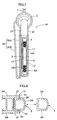
- Fig. 3 is a rear view of a cable case when retaining an apparatus body of the hand-free apparatus,
- Fig. 4 is a plan view in horizontal section showing a magnetic attraction means,
- Fig. 5 is a rear view in vertical section of the cable case,
- Fig. 6 is a rear view in vertical section showing principal portions of the cable case of Fig. 5 under a different condition,
- Fig. 7 is a side view in vertical section showing a cable case when retaining the hand-free apparatus body, and
- Fig. 8 is a plan view in horizontal section showing a retaining portion of a hand-free apparatus relating to a further embodiment of the present invention.
-
- A hand-free apparatus according to the present invention will be described next with reference to the accompanying drawings.
- As shown in Fig. 1, a hand-
free apparatus 40 according to the invention includes anapparatus body 3, a communication cable 4 (an example of input/output cable) extending from theapparatus body 3, and acable case 5 capable of storing thecable 4 therein. From thecable case 5, there is extending aconnector cable 7 for connecting thecommunication cable 4 to another electric appliance, such as a portable telephoneH. A plug 6 is attached to a free end of theconnector cable 7. Then, by connecting theconnector cable 7 to the portable telephone H via theplug 6, this hand-free apparatus may be used as an accessory or attachment for allowing hand-free use of the portable telephone H. - The
apparatus body 3 includes anarm member 3A having a longitudinal direction, and an earpiece 2 (an example of receiver) extending from an end of thearm member 3A in a direction transverse to its longitudinal direction, more particularly, with a angle of about 90 degrees relative thereto. And, a microphone 1 (an example of transmitter) is attached to the other end of thearm member 3A. Incidentally, thecommunication cable 4 extends from a through hole defined at apredetermined position 3p at approximate longitudinal center of thearm member 3A. - The
cable case 5 is provided in the form of a relatively thin plate-like component having a substantially rectangular front face (and a rear face) and substantially rectangular lateral faces. More particularly, thiscable case 5 includes a box case including a front-face case member 8A and a rear-face case member 8B screw-fixed the front-face case member 8B. The front-face case member 8A and the rear-face case member 8B both are made of synthetic resin material. - Further, the
cable case 5 includes a cable take-upmechanism 9 for taking up an excessive length of thecommunication cable 4 for its storage inside thecable case 5, depending on the necessity. This cable take-upmechanism 9 includes acable spool 11 rotatably mounted within the cable case for taking up thecommunication cable 4. As shown in Fig. 7, thecable spool 11 is formed like a disc-like member for allowing its storage within the thin plate-like cable case 5. And, thiscable spool 11 is attached via astay plate 14 to the front-face case member 8A of thecable case 8. From thestay plate 14, a shaft member 14A extends toward an inner face of the rear-face case member 8B. This shaft member 14A rotatably supports thecable spool 11. Thestay plate 14 is fixed in position relative to the front-face case member 8A by means of a plurality of holes for receiving a plurality ofpin portions 8a formed integrally with the front-face case member 8A and thestay plate 14 is pressed against the front-face case member 8A by the rear-face case member 8B. Further, the right-hand lateral face as seen from the rear face of thecable case 5 defines a throughhole 8D for guiding thecommunication cable 4 unwound from thecable spool 11 to the outside of thecable case 5. - The cable take-up
mechanism 9 further includes a helical spring 12 (an example of urging means) for urging thecable spool 11 in a rotational direction M for taking up thecommunication cable 4 and a take-up control means 13 which can be switched over between a locked condition in which the rotation of thecable spool 11 by thehelical spring 12 in the rotational direction M is restricted and a free condition in which the rotation of thecable spool 11 by thehelical spring 12 in the rotational direction M is permitted. - More particularly, the take-up control means 13 includes a saw-toothed engaging
portion 15 formed in an outer peripheral face of the pair of lateral plates constituting thecable spool 11 and aratchet member 16 pivotally mounted about an axis fixed on the front-face case member 8A. Theratchet member 16 includes apawl 16A for coming into engagement with the saw-toothed engagingportion 15 of thecable spool 11 so as to restrict the rotation of thecable spool 11 in the rotational direction M (i.e. realize the locked condition). And, thisratchet member 16 is constantly urged by an end 17a of ahelical spring 17 supported inside thecable case 5 toward a pivotal posture in which thepawl 16A is pressed against the outer peripheral face of the one lateral plate. Incidentally, total four such saw-toothedengaging portions 15 are formed with an appropriate spacing therebetween along the peripheral direction of the outer peripheral face of the one lateral face. - The take-up control means 13 further includes an operating means for switching over the take-up control means 13 to the free condition. This operating means consists essentially of the
ratchet member 16 and an operatingmember 18 for operating or controlling the pivotal posture of theratchet member 16 from the outside of thecable case 5. For this purpose, theratchet member 16 includes an operatedelement 16B extending in a direction different from that of thepawl 16A. Further, the operatingmember 18 is pivotally supported about a horizontal axis fixed inside thecable case 5. From an end of this operatingmember 18, there is extending anoperating arm 18a capable of advancing into a pivotal path of the operatedelement 16B of theratchet member 16; and aknob 18b formed on the other end of the operatingmember 18 is always exposed outside of thecable case 5. Further, the operatingmember 18 is constantly urged by the other end 17b of thehelical spring 17 in a direction of theoperating arm 18a moving away from the operatedelement 16B of theratchet member 16. - In operation, when the user depresses the
knob 18b in the direction of downward arrow in Fig. 6 (counter-clockwise rotation) against the urging force from the other end 17b of thehelical spring 17, theoperating arm 18a rotates theratchet member 16 clockwise via the operatedelement 16B against the urging force from the one end of thespring 17. With this, there is realized the free condition in which thepawl 16A is disengaged from the saw-toothed engagingportion 15. On the other hand, when the user stops depressing theknob 18b, the operatingmember 18 is returned to its home position where theknob 18a projects in the horizontal direction (the condition shown in Fig. 5), so that the force applied by theoperating arm 18a to the operatedelement 16B is immediately lost and there is realized the locked condition in which thepawl 16A of theratchet member 16 is engaged with the nearest saw-toothed engagingportion 15 under the urging force from the one end 17a of thehelical spring 17. For the purpose of setting the above-described home position of the operatingmember 18 at a fixed position, astopper portion 19 is integrally formed with the front-face case member 8A for restricting the pivotal movement of the sector (fan-shaped) portion to a predetermined fixed position. - That is to say, only while the user keeps depressing the
knob 18b, the free condition is realized temporarily and during this period alone thecable spool 11 keeps rotating in the take-up direction M for taking up thecommunication cable 4. As soon as the user stops depressing theknob 18b, in association with a small amount of subsequently continued rotation of thecable spool 11 in the take-up direction M, thepawl 16A comes into engagement with the nearest saw-toothed engagingportion 15, upon which engagement the rotation of thecable spool 11 in the take-up direction M is stopped and the taking up operation of thecommunication cable 4 too is stopped immediately. - As may be understood from the above, the single
helical spring 17 co-acts as the one urging means (provided by the one end 17a of this spring 17) for urging to the engaged position (the position realizing the locked condition) in which theratchet member 16 engages with the saw-toothed engagingportion 15 and the further urging means (provided by the other end 17b of the spring 17) for urging the operatingmember 18 to its home position (another position realizing the locked condition). Furthermore, while the user keeps his/her hand off theknob 18b, under the urging force of thespring 17 urging the sector against thestopper portion 19, the operatingmember 18 is retained at its home position in which theknob 18b projects in the horizontal direction so as not to prevent theratchet member 16 being stopped at the engaged position. Accordingly, the operatingmember 18 may be constantly maintained at its home position and will not be pivoted inadvertently, not only when thecommunication cable 4 is stopped after its withdrawal, but also while thecommunication cable 4 is being withdrawing with the pivotal movement of theratchet member 16. - The hand-
free apparatus 40 further includes a retaining means capable of detachably retaining the hand-free apparatus body 3, when not used, on thecable case 5. This retaining means includes a retainingportion 10 formed on the right-hand lateral face of thecable case 8 as seen from the rear side thereof. The retainingportion 10 retains theapparatus body 3 under a raised posture where theearpiece 2 is located above and themicrophone 1 is located below. - More particularly, this retaining
portion 10 includes ashoulder portion 20a provided an a right-upper portion thereof as seen from the rear face of thecable case 8 so as form a step-wise recessed corner, a contactedportion 20b provided at a right-lower portion as seen from the rear face of thecable case 8, and a pair of fin-like guide plates shoulder portion 20a and the contactedportion 20b. - The
shoulder portion 20a is configured to be capable of supporting theearpiece 2 of theapparatus body 3 assuming the above-described raised posture. That is, as shown in Fig. 3, theapparatus body 3 retained to the retainingportion 10 is "hooked" via itsearpiece 2 to theshoulder portion 20a. Further, the position of the throughhole 8D of thecable case 8 and the position of the attachingposition 3p of thearm member 3A for attachment of thecommunication cable 4 are arranged such that when the apparatus body b is retained to the retainingportion 10, theearpiece 2 may be pressed against theshoulder portion 20a under the urging force of thehelical spring 12 for taking up thecommunication cable 4 on thecable spool 11. - Next, the contacted
portion 20b is configured to fit the contour of themicrophone 1 for facilitating the contacting-support of thismicrophone 1 of theapparatus body 3 as hooked on theshoulder 20a via theearpiece 2. Further, the position of the throughhole 8D of thecable case 8 and the position of the attachingposition 3p of thearm member 3A for attachment of thecommunication cable 4 are arranged such that when the apparatus body b is retained to the retainingportion 10, themicrophone 1 may be pressed against the contactedportion 20b under the urging force of thehelical spring 12 for taking up thecommunication cable 4 on thecable spool 11. - Specifically, in this embodiment, when the
apparatus body 3 is retained to the retainingportion 10, the attachingposition 3p for thecommunication cable 4 on thearm member 3A is located upwardly of a rotational axis (X) of thecable spool 11 and the rotational direction M of thecable spool 11 for taking up the cable is set as the clockwise direction. Therefore, thecable spool 11 will pull thecommunication cable 4 withdrawn from theapparatus body 3 in an obliquely downward to the left-lower side, that is, in such a manner as to depress theearpiece 2 against theshoulder portion 20a and depress themicrophone 1 against the contactedportion 20b at the same time. - Lastly, the pair of
guide plates guide plates position 3p for the communication cable 4) of the arm member 3a of theapparatus body 3 hooked on theshoulder 20a via theearpiece 2 in a direction parallel to the rotational axis (X: aligned with the center of the shaft element 14A) of thecable spool 11. Namely, as the portion of theapparatus body 3 is fitted between the pair ofguide plates apparatus body 3 relative to thecable case 5 in the thickness direction thereof may be mechanically restricted. Incidentally, oneguide plate 21 is formed integrally with the front-face case member 8A during the molding thereof and theother guide member 21 is integrally formed with the rear-face case member 8B during the molding thereof, respectively. - The retaining means further includes a magnetic attraction means disposed between the
aim member 3A of theapparatus body 3 and thecable case 5. This magnetic attraction means, as shown in Fig. 4, consists essentially of apermanent magnet 22 included within a portion of theshoulder 20a of the retainingportion 10 and aniron piece 23 fixed to an inner portion immediately below theearpiece 2. Theiron piece 23 is disposed as a position to be attracted to thepermanent magnet 22 when theapparatus body 3 is retained to the retainingportion 10. Alternatively, it is also possible to provide thepermanent magnet 22 to theapparatus body 3 and theiron piece 23 to thecable case 5. - The
cable case 5 includes aclip 30 for attaching thiscase 5 to an edge of a user's clothe pocket, a belt or the like. As shown in Fig. 2, thisclip 30 includes aclip body 30A attached to thecable case 5 and aclip piece 30B which first extends horizontally from a portion near an upper end of one face of theclip body 30A and then extends downwardly for a certain length. At upper and lower ends of the other face of thedip body 30A, there are formed attaching pieces 31a, 31b in the form of pawls, which vertically oppose to each other for elastically binding thecable case 5 therebetween. In correspondence therewith, the upper and lower end faces of thecable case 5, there are defined recesses or holes for receiving the attaching pieces 31a, 31b, respectively. Thedip piece 30B, particularly its free end, is elastically deformable to move to and away from theclip body 30A, so that theclip piece 30B can elastically hold e.g. the fabric of the pocket in cooperation with theclip body 30A. - Incidentally, during the manufacture of the hand-
free apparatus 40, the recesses or holes are formed by assembling the front-face case member 8A and the rear-face member 8B by means of screw-fastening. Thereafter, only by pressing the attaching pieces 31a, 31b of theclip body 30A into these recesses or holes with utilizing the elastic deformation of theclip body 30A, theclip 30 may be attached to thecable case 5. - As shown in Fig. 8, in the pair of opposed lateral faces of the
arm member 3A of theapparatus body 3, there may be engagingrecesses arm member 3A. And, the retaining means may include a pair of engagingpieces cable case 8 for coming into elastic engagement within the engagingrecesses pieces like guide plates cable case 8 to the inner side along the rotational axis X of thecable spool 11 and thepieces guide plates pieces recesses guide plates - When the retaining means for retaining the
apparatus body 3 on thecable case 8 is comprised of the engagingrecesses pieces shoulder portion 20a, the contactedportion 20b and the magnetic attraction means provided inside the retainingportion 10 described in the foregoing embodiment will be eliminated entirely or partially. - Further alternatively, it is also possible to provide the apparatus body with a projection extending along the longitudinal direction of the
arm member 3A and also to provide a recess capable of receiving this projection to a pair of inner faces of theguide plates cable case 8. - In the foregoing embodiment, the hand-
free apparatus 40 relating to the invention has been described as an accessory or attachment for a portable telephone H. Needless to say, this hand-free apparatus 40 may be used also as an accessory or attachment for a personal computer, a transceiver or the like. - The invention may be embodied in any other manner than the disclosed embodiments without departing the spirit thereof. Therefore, the foregoing embodiments should be constructed to illustrate only the presented preferred mode of embodying the invention. Further and other modifications should be apparent for those skilled in the art within the scope of the invention defined in the appended claims.
Claims (9)
- A hand-free apparatus having:an apparatus body (3) including a transmitter (1) and a receiver (2), an input/output cable (4) connected with the transmitter and the receiver and extending outside from the apparatus body (3);a cable case (5) incorporating a cable spool (11) capable of taking up the cable (4); anda retaining means capable of detachably retaining the apparatus body (3) on the cable case (5);
characterized in thatthe apparatus body (3) when retained by the retaining means extends along a peripheral face of the cable spool (11). - The hand-free apparatus according to claim 1, characterized in that the cable case (5) includes urging means (12) for urging the cable spool (11) in a rotational direction for taking up the cable (4) and take-up control means (13) switchable between a locked condition for restricting rotation of the cable spool (11) by the urging means (12) and a free condition for allowing the rotation of the cable spool (11) by the urging means (12).
- The hand-free apparatus according to claim 2, characterized in that the apparatus body (3) includes an arm member (3A) having a longitudinal direction and the receiver (2) extends from the arm member (3A) in a direction transverse to the longitudinal direction; and the retaining means includes a shoulder portion (20a) for supporting the receiver (2) thereon.
- The hand-free apparatus according to claim 3, characterized in that the cable (4) extends from a predetermined position (3p) of the arm member (3A) and the cable case (5) defines a through hole (8D) for allowing withdrawal of the cable (4) from the cable spool (11); and a position of the through hole (8D) and the predetermined position (3p) of the arm member (3A) are arranged so as to allow the receiver (2) to be pressed against the shoulder portion (20a) under the urging force for taking up the cable (4) on the cable spool (11) when the hand-free apparatus body (3) is retained by the retaining means.
- The hand-free apparatus according to claim 4, characterized in that the retaining means includes a contacted portion (20b) formed on a lateral face of the cable case (5) for coming into contact with the transmitter (1) of the apparatus body (3) retained by the retaining means; and a position of the through hole (8D) and the predetermined position (3p) of the arm member (3A) are arranged so as to allow the transmitter (1) to be pressed against the contacted portion (20b) under the urging force for taking up the cable (4) on the cable spool (11) when the hand-free apparatus body (3) is retained by the retaining means.
- The hand-free apparatus according to claim 5, characterized in that the retaining means includes a pair of guide plates (21, 21) extending from the cable case (4) to be opposed to a portion of the apparatus body (3) retained by the retaining means in a direction parallel to a rotational axis (X) of the cable spool (11).
- The hand-free apparatus according to claim 5, characterized by an operating member (18) for switching over the take-up control means (13) to the free condition, the operating member (18) being disposed on an outer lateral face of the cable case (5) opposite from the retaining means.
- The hand-free apparatus according to claim 1, characterized in that the retaining means includes magnetic attraction means (22, 23) disposed between the arm member (3A) and the cable case (5).
- The hand-free apparatus according to claim 1, characterized in that the apparatus body (3) includes a longitudinally extending arm member (3A) which defines, in one of its opposed lateral faces, engaging recesses (24, 24) extending in the longitudinal direction; and the retaining means includes a pair of engaging elements (25, 25) extending from the cable case (5) to be elastically engaged within the engaging recesses (24, 24).
Applications Claiming Priority (2)
| Application Number | Priority Date | Filing Date | Title |
|---|---|---|---|
| JP22209099 | 1999-08-05 | ||
| JP22209099A JP2001048428A (en) | 1999-08-05 | 1999-08-05 | Cord storing device |
Publications (1)
| Publication Number | Publication Date |
|---|---|
| EP1075127A1 true EP1075127A1 (en) | 2001-02-07 |
Family
ID=16776979
Family Applications (1)
| Application Number | Title | Priority Date | Filing Date |
|---|---|---|---|
| EP00116369A Withdrawn EP1075127A1 (en) | 1999-08-05 | 2000-07-28 | Hands-free use of a communication apparatus |
Country Status (5)
| Country | Link |
|---|---|
| US (1) | US6438248B1 (en) |
| EP (1) | EP1075127A1 (en) |
| JP (1) | JP2001048428A (en) |
| KR (1) | KR20010030044A (en) |
| CN (1) | CN1139163C (en) |
Cited By (3)
| Publication number | Priority date | Publication date | Assignee | Title |
|---|---|---|---|---|
| EP1282291A1 (en) * | 2001-08-02 | 2003-02-05 | Aerotech IFE Limited | Cable reel for handset and cradle |
| WO2003031307A1 (en) * | 2001-10-05 | 2003-04-17 | Taylor Pty Ltd | Retractable cable assemblies and devices including the same |
| FR2924558A1 (en) * | 2007-12-04 | 2009-06-05 | Modelabs Technologies Ltd | Portable wireless telephonic communication accessory i.e. earphone, and charging cradle assembly for use with cellular phone, has connection unit placed between earphone and cradle, and locator preventing incorrect positioning of earphone |
Families Citing this family (98)
| Publication number | Priority date | Publication date | Assignee | Title |
|---|---|---|---|---|
| IT250988Y1 (en) * | 2000-01-05 | 2003-10-22 | Paolo Benelli | CABLE REEL DEVICE FOR PORTABLE PHONES. |
| US7373182B2 (en) * | 2002-03-01 | 2008-05-13 | Varia Mobil Llc | Wireless mobile phone including a headset |
| US20040096079A1 (en) * | 2002-11-19 | 2004-05-20 | Wang Wang Dah Enterprise Co., Ltd. | Fastening device for earphone |
| WO2005036862A2 (en) * | 2003-10-06 | 2005-04-21 | Cahp, Llc | Headset cable retraction system |
| USD501005S1 (en) * | 2004-02-28 | 2005-01-18 | Anthony George Patti | “Hands-free” mobile phone docking station and speakerphone |
| US8798305B2 (en) | 2004-07-06 | 2014-08-05 | Kaddan Entertainment, Inc. | System and method for securing headphone transducers |
| US20060035688A1 (en) * | 2004-08-12 | 2006-02-16 | Paho Saraa C | Cell phone accessory |
| CA118713S (en) * | 2006-06-14 | 2007-11-20 | Nokia Corp | Handset |
| USD566107S1 (en) * | 2007-03-19 | 2008-04-08 | Chicbwel Inc | Retractable ear buds with crystal design |
| USD569841S1 (en) * | 2007-04-18 | 2008-05-27 | Samsung Electronics Co., Ltd. | Ear-microphone |
| JP4889598B2 (en) * | 2007-08-31 | 2012-03-07 | 三洋電機株式会社 | Microphone holder and microphone device using the same |
| USD583362S1 (en) * | 2008-03-03 | 2008-12-23 | Y. C. Cable East Inc. | Retractable earphone device |
| CN101237713A (en) * | 2008-03-10 | 2008-08-06 | 新疆天地集团有限公司 | An earphone line collection device, a earphone assembly and a mobile terminal |
| USD590371S1 (en) * | 2008-04-08 | 2009-04-14 | Nokia Corporation | Headset |
| US10652661B2 (en) * | 2008-06-27 | 2020-05-12 | Snik, LLC | Headset cord holder |
| US8621724B2 (en) | 2008-06-27 | 2014-01-07 | Snik Llc | Headset cord holder |
| US8225465B2 (en) | 2008-06-27 | 2012-07-24 | Snik Llc | Headset cord holder |
| USD603846S1 (en) * | 2008-08-14 | 2009-11-10 | Samsung Electronics Co., Ltd. | Bluetooth headset |
| USD605170S1 (en) * | 2008-10-14 | 2009-12-01 | Shinhint Industries Limited | Bluetooth stereo headset |
| CN101754068A (en) * | 2008-12-09 | 2010-06-23 | 深圳富泰宏精密工业有限公司 | Electronic device |
| USD603376S1 (en) * | 2009-01-27 | 2009-11-03 | Barbara Blasko | Headset holster |
| USD608767S1 (en) * | 2009-02-12 | 2010-01-26 | Nokia Corporation | Wireless receiver |
| USD613273S1 (en) * | 2009-07-02 | 2010-04-06 | Nokia Corporation | Headset receiver |
| USD626112S1 (en) * | 2009-11-07 | 2010-10-26 | Cheng Uei Precision Industry Co., Ltd. | Earphone assembly |
| USD640241S1 (en) * | 2009-11-12 | 2011-06-21 | Victor Kingsun Wai | Sound amplification ear device with ear phone |
| US8311262B2 (en) * | 2010-03-17 | 2012-11-13 | Bose Corporation | Loudspeaker ceiling mount bracket |
| USD648315S1 (en) * | 2010-05-27 | 2011-11-08 | Cheng Uei Precision Industry Co., Ltd. | Earphone assembly |
| US8401218B2 (en) * | 2010-07-29 | 2013-03-19 | Microsoft Corporation | Adjustable earphone and earphone set |
| USD663715S1 (en) * | 2011-07-19 | 2012-07-17 | Cardo Systems, Inc. | Communications system for a helmet |
| USD670680S1 (en) * | 2011-10-03 | 2012-11-13 | Daryl Eisenmenger | Retractable ear plug housing |
| USD676833S1 (en) * | 2011-10-06 | 2013-02-26 | Francisco Garcia | Earphone cable manager/organizer |
| USD689471S1 (en) * | 2011-10-07 | 2013-09-10 | SMS Audio LLC | Pair of earbuds |
| USD692874S1 (en) * | 2011-12-12 | 2013-11-05 | Fanny Wang Headphone Company, Llc | Apparatus for conveying a signal to one or more devices |
| USD677240S1 (en) * | 2011-12-13 | 2013-03-05 | Todd Coulter | Extendible headphones |
| USD674373S1 (en) * | 2011-12-20 | 2013-01-15 | Sol Republic, Inc. | In-ear headphones |
| US9167329B2 (en) * | 2012-02-22 | 2015-10-20 | Snik Llc | Magnetic earphones holder |
| US10524038B2 (en) | 2012-02-22 | 2019-12-31 | Snik Llc | Magnetic earphones holder |
| US9769556B2 (en) | 2012-02-22 | 2017-09-19 | Snik Llc | Magnetic earphones holder including receiving external ambient audio and transmitting to the earphones |
| US9392349B2 (en) | 2012-03-30 | 2016-07-12 | Hybrid Skillz Inc. | Cable retraction system |
| US10225639B2 (en) | 2012-03-30 | 2019-03-05 | Advanced Access Technologies Llc | Cable retraction system |
| US11412627B2 (en) | 2012-03-30 | 2022-08-09 | Advanced Access Technologies Llc | Multipurpose accessory and storage system |
| US8774446B2 (en) | 2012-03-30 | 2014-07-08 | Hybrid Skillz Inc. | Retractable storage system for handheld electronic device |
| US10237990B2 (en) | 2012-03-30 | 2019-03-19 | Advanced Access Technologies Llc | Retractable storage system |
| US11432641B2 (en) | 2012-03-30 | 2022-09-06 | Advanced Access Technologies Llc | Retractable storage system |
| USD685771S1 (en) * | 2012-10-08 | 2013-07-09 | David Matthew Bertenthal | Earphone holder |
| USD712881S1 (en) * | 2013-05-24 | 2014-09-09 | Qualcomm Incorporated | Earpiece |
| USD713421S1 (en) * | 2013-07-18 | 2014-09-16 | Sony Mobile Communications Ab | Stereo handset |
| USD739377S1 (en) * | 2013-09-25 | 2015-09-22 | Lg Electronics Inc. | Wireless headset |
| KR20150047454A (en) * | 2013-09-29 | 2015-05-04 | 코비디엔 엘피 | Cable management system for medical treatment device |
| USD705421S1 (en) | 2013-10-23 | 2014-05-20 | Daryl Eisenmenger | Retractable ear plug housing |
| TWD164752S (en) * | 2014-01-06 | 2014-12-11 | 光寶電子(廣州)有限公司 | Part of clip-type wireless headset |
| US9648407B2 (en) | 2014-06-12 | 2017-05-09 | Kaddan Entertainment, Inc. | System and method for managing headphone wires |
| CN105293210A (en) * | 2014-06-19 | 2016-02-03 | 国网山西省电力公司电力科学研究院 | Freely-stretchable voltage testing wire coiling drum |
| JP1520675S (en) * | 2014-08-01 | 2015-04-06 | ||
| USD756974S1 (en) * | 2014-08-07 | 2016-05-24 | Cardo Systems, Inc. | Communication device |
| USD752019S1 (en) * | 2015-02-20 | 2016-03-22 | Robert Breines | Headphone connector |
| JP6095736B2 (en) * | 2015-07-24 | 2017-03-15 | レノボ・シンガポール・プライベート・リミテッド | Electronic device system, electronic device cover, and electronic device |
| USD791741S1 (en) * | 2015-09-20 | 2017-07-11 | Pengcheng Chen | Retractable earbuds |
| USD780726S1 (en) * | 2015-12-04 | 2017-03-07 | Howard Wang | Wireless adapter |
| USD804445S1 (en) * | 2016-01-05 | 2017-12-05 | Fossil Group, Inc. | In-ear headphones |
| JP2017140275A (en) * | 2016-02-12 | 2017-08-17 | 大東電機工業株式会社 | Remote control device provided in chair type massage machine |
| US11272281B2 (en) | 2016-04-19 | 2022-03-08 | Snik Llc | Magnetic earphones holder |
| US10455306B2 (en) | 2016-04-19 | 2019-10-22 | Snik Llc | Magnetic earphones holder |
| US10631074B2 (en) | 2016-04-19 | 2020-04-21 | Snik Llc | Magnetic earphones holder |
| US10951968B2 (en) | 2016-04-19 | 2021-03-16 | Snik Llc | Magnetic earphones holder |
| US10225640B2 (en) | 2016-04-19 | 2019-03-05 | Snik Llc | Device and system for and method of transmitting audio to a user |
| USD823279S1 (en) * | 2016-04-21 | 2018-07-17 | Shenzhen Voxtech Co., Ltd. | Bone conduction speaker |
| JP1573977S (en) * | 2016-05-12 | 2017-04-17 | ||
| USD798838S1 (en) * | 2016-07-27 | 2017-10-03 | Polk Audio, Llc | USB audio speaker |
| USD810724S1 (en) * | 2016-08-31 | 2018-02-20 | Harman International Industries, Incorporated | Headphone |
| USD843340S1 (en) * | 2016-09-19 | 2019-03-19 | My Core Control Development, Llc | Collar device |
| CN106292159A (en) * | 2016-09-26 | 2017-01-04 | 北京小米移动软件有限公司 | Micro projector |
| JP1584601S (en) * | 2017-01-03 | 2017-08-28 | ||
| USD841619S1 (en) * | 2017-03-24 | 2019-02-26 | Klein Electronics, Inc. | Two-way radio headset with boom microphone |
| USD842839S1 (en) * | 2017-03-24 | 2019-03-12 | Klein Electronics, Inc. | Dual ear piece mobile phone headset with boom microphone |
| USD839242S1 (en) * | 2017-04-17 | 2019-01-29 | Shenzhen Riitek Technology Co., Ltd. | Clip-on wireless headset |
| JP1622041S (en) * | 2017-05-18 | 2019-01-15 | ||
| USD830347S1 (en) * | 2017-06-30 | 2018-10-09 | Inmusic Brands, Inc. | Microphone |
| JP1610198S (en) * | 2017-09-25 | 2018-07-30 | ||
| USD839850S1 (en) * | 2017-09-29 | 2019-02-05 | Shenzhen Meidong Acoustics Co., Ltd | Earphone |
| USD890099S1 (en) | 2018-05-16 | 2020-07-14 | Klein Electronics, Inc. | Ruggedized side connector for audio accessories |
| USD874427S1 (en) * | 2018-08-02 | 2020-02-04 | Lorenzo Young Davis | Earbud cover |
| JP1628023S (en) * | 2018-09-27 | 2019-04-01 | ||
| USD975645S1 (en) | 2018-12-04 | 2023-01-17 | Klein Electronics, Inc. | Secure audio accessory connector |
| USD888009S1 (en) * | 2019-01-03 | 2020-06-23 | Ningbo Gecen Promotion & Gift Co., Ltd. | Ear phone |
| USD892097S1 (en) * | 2019-01-04 | 2020-08-04 | Furrion Property Holding Limited | Electronic speaker assembly |
| USD893447S1 (en) * | 2019-01-29 | 2020-08-18 | Shure Acquisition Holdings, Inc. | Wireless bodypack |
| USD920287S1 (en) * | 2019-05-07 | 2021-05-25 | MBRIO Technologies LLC | Set of prenatal earbud adapters |
| USD911317S1 (en) * | 2019-08-14 | 2021-02-23 | Skullcandy, Inc. | Base module for earphones |
| USD1016785S1 (en) * | 2019-08-19 | 2024-03-05 | Inova Design Solutions Ltd | Ear bud |
| USD928740S1 (en) | 2019-08-30 | 2021-08-24 | Klein Electronics, Inc. | Touchscreen push-to-talk button |
| USD973640S1 (en) * | 2020-09-17 | 2022-12-27 | Shenzhen Jiayz Photo Industrial., Ltd | Wireless microphone |
| USD982549S1 (en) * | 2021-04-09 | 2023-04-04 | Shenzhen Liangbao Technology Co., Ltd. | Headphone adapter |
| WO2023014378A1 (en) * | 2021-08-06 | 2023-02-09 | Noah Sapir | Apparatus and method for wireless earpiece holder with one-handed operation |
| JP1720080S (en) * | 2021-10-29 | 2022-07-19 | Data communication adapter | |
| USD982561S1 (en) * | 2023-01-09 | 2023-04-04 | Shenzhen Shengling Technology Co., Ltd | Earphone |
| USD1055029S1 (en) * | 2023-01-11 | 2024-12-24 | Jrumz Ear Wear LLC | Pair of wireless earphones |
| USD1093339S1 (en) * | 2025-01-16 | 2025-09-16 | Zhaoqing Junfeng Electronics Co., Ltd | Headset |
Citations (4)
| Publication number | Priority date | Publication date | Assignee | Title |
|---|---|---|---|---|
| US5684883A (en) * | 1996-11-26 | 1997-11-04 | E Lead Electronic Co., Ltd. | Device for receiving earphone/microphone wire of holdfree hand set |
| US5832098A (en) * | 1997-08-22 | 1998-11-03 | E. Lead Electronic Co., Ltd. | Earphone/microphone assembly |
| JPH1155778A (en) * | 1997-08-05 | 1999-02-26 | Mona Seiki Kk | Cord reel for earphone |
| JPH1155369A (en) * | 1997-08-06 | 1999-02-26 | Murata Mach Ltd | Portable telephone set |
Family Cites Families (4)
| Publication number | Priority date | Publication date | Assignee | Title |
|---|---|---|---|---|
| JPH0434608Y2 (en) * | 1987-03-30 | 1992-08-18 | ||
| US4946010A (en) * | 1989-03-30 | 1990-08-07 | Dibono Peter A | Telephone cord retraction device |
| US5128993A (en) * | 1990-11-28 | 1992-07-07 | Gte Airfone, Incorporated | Telephone dispenser with compact cord guide |
| US5422957A (en) * | 1994-01-18 | 1995-06-06 | Cummins; Robert C. | Cable take-up for earphones |
-
1999
- 1999-08-05 JP JP22209099A patent/JP2001048428A/en active Pending
-
2000
- 2000-07-28 EP EP00116369A patent/EP1075127A1/en not_active Withdrawn
- 2000-08-01 US US09/630,232 patent/US6438248B1/en not_active Expired - Fee Related
- 2000-08-01 KR KR1020000044550A patent/KR20010030044A/en not_active Ceased
- 2000-08-04 CN CNB001270192A patent/CN1139163C/en not_active Expired - Fee Related
Patent Citations (4)
| Publication number | Priority date | Publication date | Assignee | Title |
|---|---|---|---|---|
| US5684883A (en) * | 1996-11-26 | 1997-11-04 | E Lead Electronic Co., Ltd. | Device for receiving earphone/microphone wire of holdfree hand set |
| JPH1155778A (en) * | 1997-08-05 | 1999-02-26 | Mona Seiki Kk | Cord reel for earphone |
| JPH1155369A (en) * | 1997-08-06 | 1999-02-26 | Murata Mach Ltd | Portable telephone set |
| US5832098A (en) * | 1997-08-22 | 1998-11-03 | E. Lead Electronic Co., Ltd. | Earphone/microphone assembly |
Non-Patent Citations (1)
| Title |
|---|
| PATENT ABSTRACTS OF JAPAN vol. 1999, no. 05 31 May 1999 (1999-05-31) * |
Cited By (4)
| Publication number | Priority date | Publication date | Assignee | Title |
|---|---|---|---|---|
| EP1282291A1 (en) * | 2001-08-02 | 2003-02-05 | Aerotech IFE Limited | Cable reel for handset and cradle |
| WO2003031307A1 (en) * | 2001-10-05 | 2003-04-17 | Taylor Pty Ltd | Retractable cable assemblies and devices including the same |
| US7032728B2 (en) | 2001-10-05 | 2006-04-25 | Taylor Pty Ltd | Retractable cable assemblies and devices including the same |
| FR2924558A1 (en) * | 2007-12-04 | 2009-06-05 | Modelabs Technologies Ltd | Portable wireless telephonic communication accessory i.e. earphone, and charging cradle assembly for use with cellular phone, has connection unit placed between earphone and cradle, and locator preventing incorrect positioning of earphone |
Also Published As
| Publication number | Publication date |
|---|---|
| CN1289162A (en) | 2001-03-28 |
| US6438248B1 (en) | 2002-08-20 |
| KR20010030044A (en) | 2001-04-16 |
| CN1139163C (en) | 2004-02-18 |
| JP2001048428A (en) | 2001-02-20 |
Similar Documents
| Publication | Publication Date | Title |
|---|---|---|
| US6438248B1 (en) | Hand-free apparatus | |
| US7802746B2 (en) | Hanging device | |
| US6480611B2 (en) | Headphone having a cord reel | |
| US6032337A (en) | Spring loaded belt clip assembly for a communication device | |
| US6082656A (en) | Electronic device with retractable cord | |
| US7492917B2 (en) | Headphone with cord take-up device | |
| US20060009069A1 (en) | Cord retainer | |
| JPH04102560U (en) | Structure to prevent battery covers from falling off of wireless communication equipment, etc. | |
| CA2319988A1 (en) | Brake device for a tape rule | |
| CN114095819B (en) | Headphone Cases and Sets | |
| HK1033229A (en) | Hands-free use of a communication apparatus | |
| US3953688A (en) | Cord reel and writing pad attachment for telephones | |
| JP3237622B2 (en) | Mobile terminal device strap structure | |
| JP3042118U (en) | Organizer for earphone cords for mobile phones | |
| CN222582568U (en) | Easy-to-store wired earphone box | |
| KR200178343Y1 (en) | Ear-mike set | |
| JPH0211721Y2 (en) | ||
| CN221748556U (en) | Earphone box, earphone assembly and wearable electronic device | |
| JP3676982B2 (en) | Electronics | |
| JP4415623B2 (en) | Camera adapter | |
| JPH04357741A (en) | Handset with telephone number card | |
| JP2000260484A (en) | Charger for wireless telephone | |
| JP2001326712A (en) | Hand strap having earphones | |
| JPH1064493A (en) | Battery pack lock structure for mobile phones | |
| JP2663778B2 (en) | Small mobile phone |
Legal Events
| Date | Code | Title | Description |
|---|---|---|---|
| PUAI | Public reference made under article 153(3) epc to a published international application that has entered the european phase |
Free format text: ORIGINAL CODE: 0009012 |
|
| AK | Designated contracting states |
Kind code of ref document: A1 Designated state(s): DE FI FR GB SE |
|
| AX | Request for extension of the european patent |
Free format text: AL;LT;LV;MK;RO;SI |
|
| 17P | Request for examination filed |
Effective date: 20010228 |
|
| AKX | Designation fees paid |
Free format text: DE FI FR GB SE |
|
| 17Q | First examination report despatched |
Effective date: 20080609 |
|
| GRAP | Despatch of communication of intention to grant a patent |
Free format text: ORIGINAL CODE: EPIDOSNIGR1 |
|
| GRAP | Despatch of communication of intention to grant a patent |
Free format text: ORIGINAL CODE: EPIDOSNIGR1 |
|
| STAA | Information on the status of an ep patent application or granted ep patent |
Free format text: STATUS: THE APPLICATION IS DEEMED TO BE WITHDRAWN |
|
| 18D | Application deemed to be withdrawn |
Effective date: 20090317 |
|
| REG | Reference to a national code |
Ref country code: HK Ref legal event code: WD Ref document number: 1033229 Country of ref document: HK |