EP1075105A1 - Selbstgeschütztes optisches Kommunikationsringnetzwerk - Google Patents
Selbstgeschütztes optisches Kommunikationsringnetzwerk Download PDFInfo
- Publication number
- EP1075105A1 EP1075105A1 EP00305519A EP00305519A EP1075105A1 EP 1075105 A1 EP1075105 A1 EP 1075105A1 EP 00305519 A EP00305519 A EP 00305519A EP 00305519 A EP00305519 A EP 00305519A EP 1075105 A1 EP1075105 A1 EP 1075105A1
- Authority
- EP
- European Patent Office
- Prior art keywords
- optical
- txt
- rxt
- wavelength
- optical carrier
- Prior art date
- Legal status (The legal status is an assumption and is not a legal conclusion. Google has not performed a legal analysis and makes no representation as to the accuracy of the status listed.)
- Granted
Links
Images


Classifications
-
- H—ELECTRICITY
- H04—ELECTRIC COMMUNICATION TECHNIQUE
- H04J—MULTIPLEX COMMUNICATION
- H04J14/00—Optical multiplex systems
- H04J14/02—Wavelength-division multiplex systems
- H04J14/0287—Protection in WDM systems
- H04J14/0293—Optical channel protection
- H04J14/0295—Shared protection at the optical channel (1:1, n:m)
-
- H—ELECTRICITY
- H04—ELECTRIC COMMUNICATION TECHNIQUE
- H04J—MULTIPLEX COMMUNICATION
- H04J14/00—Optical multiplex systems
- H04J14/02—Wavelength-division multiplex systems
- H04J14/0278—WDM optical network architectures
- H04J14/0283—WDM ring architectures
Definitions
- the present invention relates to an optical communication system, and more particularly to a WDM (Wavelength Division Multiplexing) autoprotected optical communication ring network.
- WDM Widelength Division Multiplexing
- Optical communication ring network refers not only to an entire communication network that is configured as a ring, but in general, any section of a network that comprises a plurality of nodes and branches, and that is arranged, at least temporarily, in a ring configuration.
- “Failure” as used herein refers to any event or condition which may affect the physical optical carriers (e.g., breakage or interruption of an optical fiber) and/or the devices of the network that operate on the transmitted signals (e.g., receivers, demultiplexers, amplifiers, etc.), in such a way as to bring about a situation of degradation of the transmission below a tolerable level; the term “failure” thus should in no way be interpreted as being limited only to events causing the complete interruption of the connection.
- European Patent Application No. 769859 (in the name of the Applicant) relates to a transparent optical self healing-rind communication network in which at least two nodes are optically connected along a first and a second closed optical path having opposite transmission directions. Each node simultaneously feeds its transmitted signals to the first and the second closed optical pathes, so that the signals travel along complementary arcs of the ring. The receiving node selectively receives the signals from one of the two closed paths and, in case of failure on this closed path, switches reception on the other closed path.
- this Optical Channel Protection method known as a "Optical Channel 1+1 Dedicated Ring Protection” method; requires that, for each wavelength used on one closed path, the same wavelength cannot be used on the other closed path other than for protection.
- N wavelengths only N protected channels can be used in the network.
- European Patent Application No. 97123013.1-2209 (filed on December 31, 1997 by the Applicant) relates to a method and an apparatus for transparent optical communication with two-fiber bidirectional ring with autoprotection and management of low priority traffic.
- the communication network comprises two optical fibers (an external one and an internal one) that interconnect the nodes.
- a high-priority traffic can be set up on a first bidirectional communication path defined between the two nodes on the external and internal fibers, using only an arc of the communication ring defined between the two nodes.
- the arc complementary to that just described can be used as a second bidirectional communication path between the two nodes for low-priority traffic, using the same wavelength as the preceding channel.
- the protection mechanism consists of redirecting the high-priority traffic onto the second path in the case of a breakdown or degradation of communication on the first path, thus losing the low-priority traffic on the second path.
- This protection method is identifiable as a "Optical Channel 1:1 Dedicated Ring Protection" method with management of Low-Priority traffic. It is observed that, although this method provides a double capacity with respect to the previous technique, with N wavelengths it is still not possible to protect more than N channels.
- This protection method is known as "Optical Multiplex Section Protection” method. It is once again observed that with N wavelengths, only N protected channels can be used. Additionally, under this approach, it is not possible to have different protection mechanisms (i.e., protection at different layers) for different channels, and that the optical path after a protection reconfiguration can be longer than the ring circumference.
- U.S. Patent No. 5,647,035 discloses a ring network communication structure on an optical carrier and a reconfigurable node for the structure.
- a plurality of nodes are interconnected by means of connections that include at least a first and a second optical carriers such as an optical fiber. Transmission between two nodes occurs on the ring according to a WDM scheme, by utilizing a first wavelength for communication in one direction on the first carrier and a second wavelength for communication in the opposite direction on the second carrier.
- the second wavelength on the first carrier and the first wavelength on the second carrier are reserved for protection (protection channels) and are "shared" among all the nodes.
- each node Under regular operation conditions of the network, in each node the signals conveyed by the two fibers are detected, processed as required in units of a higher hierarchical level, converted again in optical signals and re-transmitted towards a subsequent node.
- the nodes adjacent to the failed connection reconfigure themselves to ensure the continuation of communication on the alternative path provided by the ring, by utilizing the first wavelength on the second carrier and the second wavelength on the first carrier.
- the described exemplary embodiment referring to just two wavelengths ⁇ 1 , ⁇ 2 , can be generalized to any number of wavelengths with a corresponding expansion of the described connection; switching matrices of the nxn type may be used.
- each node in the network must be equipped with the optical switching tools for the complete set of wavelengths in the ring, and a switch matrix is then needed with a complexity which increases considerably with increasing the number of channels (e.g., if each channel carries 2.5 Gb/s and the system is adapted to transmit 16 channels, each matrix must be able to switch 16 x 2.5 Gb/s).
- the number of optical switching blocks that are required to protect N to MN/2 number of links is always MN.
- a failure on a single optical channel (e.g., when a node transmitter is damaged) may be either ignored or may cause the reconfiguration of all the traffic, thereby causing a temporary failure of all the other working channels.
- the protection path of a generic optical channel may be longer than the maximum ring circumference. This can occur when a generic bidirectional link is set up between two non-adjacent nodes in the network, as illustrated in Figure la (where nodes A and D are involved). In case of failure the switching action is performed by the two nodes adjacent to the failure (i.e., nodes B and C), as shown in Figure 1b. Each channel of the bidirectional link travels along the working path from the source node to one of the reconfigured nodes where it is routed into the protection path.
- This alternative optical channel path may have a length that exceeds the ring circumference, reaching values of several hundred kilometers and thus, causing a low S/N ratio and high levels of attenuation.
- this protection solution may lead, due to loopbacks, to restoration transmission paths that would cross the ocean three times.
- U.S. Patent No. 5.647,035 proposes a solution in which the failure control is over the entire optical multiplex section. It is noted that this solution may result in ignoring a failure on a single optical channel. In addition, the failure may cause the reconfiguration of all the traffic, resulting in temporary failure of all other working channels.
- the present invention provides an improved shared protection technique, in which re-routing operations are performed only at the nodes that terminate the affected links and only on the failed channels, thus avoiding the drawbacks related to re-routing operations on the multiplex section.
- An optical reconfigurable connection mechanism allows the omission of a SDH layer protection mechanism.
- the failure control is performed at the channel level, instead of the multiplex section level, thus overcoming the above mentioned drawbacks.
- the nodes communicate in pairs (defining bidirectional links), and under normal conditions, are optically configured to exchange signals on a respective working arc path at a respective first wavelength on a first carrier of the network and at a respective second wavelength on a second carrier of the network.
- the same wavelengths may be used in the same manner to define other links, while the first wavelength on the second carrier and the second wavelength on the first carrier are reserved for protection and are used in case of failure that affects one of the links.
- Each node of the proposed network is provided with a pair of OADM (Optical Add/Drop Multiplexers) for extracting from, and inserting in, the optical multiplex section, only the channels which the node is adapted to operate on. All the remaining channels are passed-through.
- OADM Optical Add/Drop Multiplexers
- Each node is further provided with a receiving/transmitting module for each pair of wavelengths defining a transmission link, said module optically connecting, in a selective way, the OADMs to optical transmitters and receivers operating at the wavelengths.
- Each receiving/transmitting module performs failure control and re-routing operations on the two corresponding wavelengths. Consequently, in case of failure, if one of the links managed by this node fails, the corresponding receiving/transmitting module, after detecting the failure by checking the channels status. is reconfigured in order to optically re-route the transmission on the complementary portion of the ring. The same operation is performed by the node at the other end of the failed link. Therefore, only the nodes that manage the affected links are optically reconfigured, and only the failured channels (instead of the global multiplex section) are re-routed.
- the protection technique of the invention provides a number of advantages.
- optical protection can be provided to a selected subset of optical channels, leaving the protection of the remaining channels up to the other layers (e.g., SDH) or to other optical protection mechanisms.
- SDH optical re-routing mechanism
- the proposed protection technique is therefore compatible with every client electronic transmission protocol.
- the receiving/transmitting module in the protection scheme of the present invention includes an optical switching unit which, in contrast to the SDH switching layouts, can operate at different bit rates (e.g., 155 Mbit/s, 622 Mbit/s, 2,5 Gbit/s, 10 Gbit/s).
- the protection approach of the present invention enables client to client protection, because a failure is detectable, even if it affects a single channel.
- the prior art techniques generally allow only global failure detection on the multiplexed flux (by using threshold photodiodes).
- the number of switching blocks is always two times the number of protected channels (i.e., between 2N and MN, where N is the number of wavelengths and M the number of nodes) thus giving an advantage, with mixed traffic patterns, over the Optical Multiplex Section Shared Protection schema proposed in US 5,647,035.
- M 8 wavelengths optical ring network
- N 32 wavelengths optical ring network
- the required number of switching blocks for said Optical Multiplex Section Shared Protection schema is always 256.
- the required number of switching blocks varies between 64 (in case of "hub traffic", i.e., one node communicating with all the other nodes) and 256 (in case of "uniform traffic", i.e., one node communicating only with its two adjacent nodes).
- the complexity of the node switching structure depends only on the number of links that are managed by the nodes, not on the number of wavelengths in the network. Additionally, the switching operations are performed external to the network; as such, no transitories are present. In particular, switching of the single channel is performed, as described below, between the receiving and the transmitting transponders. Therefore, the multiplexed optical flux conditions at the input of the node amplifier are substantially unchanged. Consequently, sudden power variations inside the network are avoided.
- an autoprotected optical communication system comprises a first optical carrier that is configured to transport optical signals in a first direction.
- a second optical carrier is configured to transport optical signals in a second direction that is opposite to the first direction.
- a plurality of nodes are connected along the first optical carrier and the second optical carrier to form bidirectional links.
- the plurality of nodes communicate in pairs. One of the pairs defines a working link that is associated with a portion of the first optical carrier and a portion of the second optical carrier.
- the pair of nodes are configured to exchange optical sisals using a first wavelength on the first optical carrier and a second wavelength that is different from the first wavelength on the second optical carrier during a normal condition.
- the one pair of nodes are configured to exchange optical signals using the first wavelength on the second optical carrier and the second wavelength on the first optical carrier during a failure condition.
- each of the plurality of nodes selectively uses a predetermined subset of wavelengths within a set of transmission wavelengths ( ⁇ 1 , ⁇ 2 , ..., ⁇ N ).
- Each of the plurality of nodes comprises a plurality of optical add/drop multiplexers that are serially connected to the first optical carrier and the second optical carrier, respectively.
- Each of the optical add/drop multiplexers is configured to selectively perform at least one of adding the subset of wavelengths to the first optical carrier and to the second optical carrier, dropping the subset of wavelengths from the first optical carrier and the second optical carrier, and bypassing remaining wavelengths of the set of transmission wavelengths ( ⁇ 1 , ⁇ 2 , ..., ⁇ N ).
- each of the plurality of nodes comprises an optical transmitter, an optical receiver, and a reconfigurable optical switch unit that selectively couples the optical transmitter and the receiver to the first optical carrier and the second optical carrier.
- each of the plurality of nodes comprises a plurality of information insertion devices that optically coupled to the optical transmitter and configured to insert signalling information into the optical signals.
- a plurality of information extraction devices optically are coupled to the optical receiver and configured to extract signalling information from the optical signals.
- the plurality of information insertion devices and the plurality of information extraction devices include optical transponders that optically couple the optical switch unit to the first optical carrier and the second optical carrier.
- the optical transponders are configured to change wavelengths of the optical signals.
- a method of providing autoprotection in an optical ring network which includes a first optical carrier, and a second optical carrier, and a plurality of nodes that are connected along the first optical carrier and the second optical carrier and are configured to communicate in pairs to define bidirectional links.
- the method includes exchanging optical signals between one of the pairs of nodes over one of the bidirectional links by using a first wavelength on the first optical carrier and a second wavelength on the second optical carrier during normal operation.
- the method also includes detecting a failed link among the bidirectional links, and reconfiguring the nodes in the one pair to invoke a protection scheme that uses the first wavelength on the second optical carrier and the second wavelength on the first optical carrier to avoid the failed link.
- the method also includes using a predetermined subset of wavelengths within a set of transmission wavelengths that are carried by the first optical carrier and the second optical carrier, wherein the step of exchanging includes optically separating, at each node of the plurality of nodes, each wavelength of the subset of wavelengths from the set of transmission wavelengths.
- the step of detecting includes verifying, in each of the plurality of nodes and for each wavelength in the set of wavelengths, whether the optical signals are received.
- the step of detecting includes verifying, in each of the plurality of nodes and for each wavelength in the set of wavelengths, whether the optical signals are degraded.
- the step of detecting includes verifying, in each of the plurality of nodes and for each wavelength in the set of wavelengths, whether the optical signals include a failure message.
- the method further includes transmitting a failure message between the nodes in the one pair based upon at least one of non-receipt of the optical signals and receipt of the optical signals that are degraded.
- the step of reconfiguring includes switching optical connections which selectively couple an optical transmitter and an optical receiver to the first optical carrier and the second optical carrier.
- a reconfigurable node of an autoprotected optical communication ring network which has a first optical carrier and a second optical carrier, comprises an optical transmitter that is configured to generate optical signals.
- An optical receiver (Rx 1 ) is configured to receive optical sisals.
- a plurality of transmitting transponders are optically coupled to the first optical carrier and the second optical carrier.
- a plurality of receiving transponders are optically coupled to the first optical carrier and the second optical carrier.
- a plurality of optical switches are coupled to the transmitting transponders and the receiving transponders.
- One of the optical switches is coupled to the optical transmitter; another one of the optical switches is coupled to the optical receiver.
- the optical switches are configured to operate selectively under a normal operating condition and under a failure condition.
- the transponders use a first wavelength on the first optical carrier and a second wavelength that is different from the first wavelength on the second optical carrier during the normal condition. During the failure condition, the transponders use the first wavelength on the second optical carrier and the second wavelength on the first optical carrier.
- the plurality of transmitting transponders include a first transmitting transponder that is optically coupled to the first optical carrier and is configured to modulate a sisal at the first wavelength.
- a second transmitting transponder (TxT 1 ( ⁇ y )) is optically coupled to the first optical carrier and is configured to modulate a signal at a second wavelength.
- a third transmitting transponder is optically coupled to a second optical carrier and is configured to modulate a signal at the first wavelength.
- the plurality of receiving transponders include a first receiving transponder that is optically coupled to the first optical carrier and is configured to demodulate a signal at the first wavelength.
- a second receiving transponder is optically coupled to the first optical carrier and configured to demodulate a signal at the second wavelength.
- a third receiving transponder is optically coupled to the second optical carrier and is configured to demodulate a signal at the second wavelength.
- the optical switches are configured to connect the optical transmitter to the first transmitting transponder and to the third transmitting transponder, to connect the first receiving transponder to the third transmitting transponder, to connect the second receiving transponder to the optical receiver, and to connect the third receiving transponder to the optical receiver and to the second transmitting transponder.
- the node further includes another optical transmitter that is configured to generate an optical signal that includes information to be transmitted in the network, and another optical receiver that is configured to receive an optical signal that includes information has been transmitted in the network.
- the plurality of transmitting transponders includes a fourth transmitting transponder that is optically coupled to the second optical carrier and is configured to modulate a signal at the second wavelength.
- the plurality of receiving transponders include a fourth receiving transponder that is optically coupled to the first optical carrier and is configured to demodulate a signal at the first wavelength.
- the optical switches are configured to connect the first receiving transponder to the third transmitting transponder and to the other receiver, to connect the fourth receiving transponder to the other receiver, and to connect the other optical transmitter to the second transmitting transponder and to the fourth transmitting transponder.
- the first wavelength and the second wavelength are selected from a set of transmission wavelengths ( ⁇ 1 , ⁇ 2 , ..., ⁇ N ).
- the node further includes a plurality of optical add/drop multiplexers that are configured to optically couple the transmitting transponders and the receiving transponders to the first optical carrier and the second optical carrier to feed and extract a subset of wavelengths from the optical carriers, and to pass-through a remaining wavelengths of the set of transmission wavelengths ( ⁇ 1 , ⁇ 2 , ..., ⁇ N ).
- the optical switches include 2x2 switches, or alternatively, 1x2 and 2x 1 switches.
- the optical switches include discrete switching components or, alternatively, an integrated switching matrix.
- the optical switches include at least one of opto-mechanical switches, thermo-optical switches, magneto-optical switches, liquid crystal switches, semiconductor switches, electro-optical switches, micro-mechanical switches, and lithium niobate integrated circuit switches.
- Network 1 includes a first and a second optical fiber ring 2, 3 defining respective optical carriers that have opposite transmission directions.
- the network 1 also includes a plurality of nodes 20a-20f, which are positioned along the first and the second ring 2, 3, for adding and dropping optical signals.
- Network 1 is adapted for both terrestrial transmissions and transoceanic transmissions. For long-haul transmissions, in particular, transoceanic transmissions, network 1 is preferably provided with line optical amplifiers and/or boosters and/or preamplifiers (not shown).
- rings 2, 3 define an external ring having a counter-clockwise transmission direction and an internal ring with a clockwise transmission direction, respectively.
- the number of nodes in network 1 is six; however, the present invention has applicability to networks with any number of nodes.
- network 1 is shown to have two optical fibers; it is recognized by one of ordinary shill in the art that the nodes can be connected by any number of optical carriers.
- Network 1 Communication in network 1 is achieved according to a Wavelength Division Multiplexing (WDM) scheme using different channels at respective wavelengths on each ring.
- rings 2, 3 are adapted to convey optical signals in the transmission channels defined by a set of transmission wavelengths ⁇ 1 , ⁇ 2 , ..., ⁇ N within a predetermined wavelength transmission band.
- Each of the nodes 20a-20f is adapted to manage a respective subset of wavelengths within the set of transmission wavelengths ⁇ 1 , ⁇ 2 , ..., ⁇ N and to define bidirectional communication with one or more of the other nodes of network 1.
- Each pair of nodes which is arranged to mutually communicate, splits network 1 into two complementary arc paths, at least one of which (identifiable as a "working path") allows bidirectional transmission between the two nodes under normal operating conditions (i.e., without failures), and the other (identifiable as a "protection path”) accepts re-routed transmissions in the presence of a failure in the working path.
- a pair of nodes are arranged to exchange data through the use of wavelengths ⁇ x , ⁇ y .
- a bi-directional working link is established by transmitting optical signals at the first wavelength ⁇ x on the external ring 2 (in the counter clockwise direction) and at the second wavelength ⁇ y on the internal ring 3 (in the clockwise direction).
- the second wavelength ⁇ y is not used on the external ring 2; the first wavelength ⁇ x is used on the internal ring 3.
- the second wavelength ⁇ y and the first wavelength ⁇ x can then be used on the external ring 2 and, respectively, on the internal ring 3, to provide optical protection, as hereinbelow described.
- the wavelengths that are used under normal operating conditions (i.e., ⁇ x on the external ring 2 and ⁇ y , on the internal ring 3) to perform working links are identified with a "w" suffix ( ⁇ x,w , ⁇ y,w ), while the wavelengths which are adapted to be used for protection (i.e., ⁇ y on the external ring 2 and ⁇ x on the internal ring 3) are identified with a "p" suffix ( ⁇ x,p , ⁇ y,p ).
- the first and the second wavelengths ⁇ x , ⁇ y can be used on the protection path associated with the corresponding pair of nodes to perform a further bidirectional working link between the first and the second node or to perform further bidirectional working links between other pairs of nodes (which may include one of the previously considered nodes), provided that those further working links do not overlap with each other and with the above considered one.
- the pair of wavelengths ⁇ x , ⁇ y defines a "logical ring", i.e., a virtual ring which may include many non-overlapping working links operating at ⁇ x,w , ⁇ y,w .
- Protection wavelengths ⁇ x,p , ⁇ y,p are not used under normal operating conditions, and are shared among the different working links operating at ⁇ x,p , ⁇ y,p (i.e., on the same logical ring). Overlapping working links can only be part of different logical rings and operate at different wavelengths.
- the number of working links in a single logic ring depends on the client traffic pattern. For example, with M nodes and N wavelengths (N even), in case of "hub traffic" (i.e., one node communicating with all the other nodes) a maximum of N protected working links can be established because each logical ring can support only two working links, while in case of "uniform traffic" (i.e., each node communicating only with its two adjacent) a maximum of MN/2 protected working links are available because each logical ring (i e., each pair of wavelengths) can support M working links.
- hub traffic i.e., one node communicating with all the other nodes
- MN/2 protected working links are available because each logical ring (i e., each pair of wavelengths) can support M working links.
- one working link is set up between node 20c and node 20f using the first working wavelength ⁇ x,w on the external ring 2 and the second working wavelength ⁇ y,w on the internal ring 3.
- Another working link is set up with the same wavelengths (and directions of propagation on the two rings 2, 3) between node 20d and node 20e.
- each of nodes 20a-20f provides optical add/drop/bypass functions for each wavelength within the wavelength transmission band on both the external and internal fiber rings 2, 3, together with optical amplification and regeneration (if necessary).
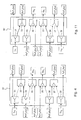
- FIG. 3 shows the structure of a generic node 20i of network 1, in particular of a node operating at wavelengths ⁇ x and ⁇ y .
- Node 20i includes optical add/drop multiplexers (OADM) 4, 5 and a receiving/transmitting module 6.
- OADM optical add/drop multiplexers
- the receiving/transmitting module 6 contains the following components: transmitters Tx 1 , Tx 2 ; receivers Rx 1 , Rx 2 ; transmitting transponders TXT 1 ( ⁇ x ), TxT 1 ( ⁇ y ), TxT 2 ( ⁇ x ), TXT 2 ( ⁇ y ); receiving transponders RxT 1 ( ⁇ x ), RxT 1 ( ⁇ y ), RxT 2 ( ⁇ x ), RxT 2 ( ⁇ y ); a switch unit 15; and a central processing unit (CPU) 16.
- transmitters Tx 1 , Tx 2 ; receivers Rx 1 , Rx 2 ; transmitting transponders TXT 1 ( ⁇ x ), TxT 1 ( ⁇ y ), TxT 2 ( ⁇ x ), TXT 2 ( ⁇ y ); receiving transponders RxT 1 ( ⁇ x ), RxT 1 ( ⁇ y ), RxT 2 ( ⁇ x ), RxT 2 ( ⁇
- the OADMs 4, 5 have the capability to insert and extract optical signals at the working and protection wavelengths associated with node 20i (i.e., ⁇ x and ⁇ y ) into rings 2, 3, and to bypass the other transmission wavelengths, If required, OADMs 4, 5 may perform other functions within the wavelength transmission band, such as regeneration, performance monitoring, etc.
- the OADM 4 is coupled to the fiber of the external ring 2 for performing add/drop functions, while OADM 5 performs the add/drop functions on the internal ring 3 OADMs 4 and 5 may be implemented, for example, using the Pirelli Optical Systems OADM/P4-R1 (WaveMux6400 product family).
- Transmitters Tx 1 , Tx 2 and receivers Rx 1 , Rx 2 represent the client access points for the input and the output of information.
- transmitters Tx 1 , Tx 2 accept the input of information that are addressed to the two receivers that are connected to network 1.
- the input of information by transmitters Tx 1 , Tx 2 may be performed at wavelengths not included in the transmission wavelength band of network l, since the transmitting transponders TxTs provide the signals with the correct wavelength (i.e., with the first wavelength ⁇ x or the second wavelength ⁇ y ), Tx 1 , Tx 2 may be, for example, a standard Sonet OC-48/SDH STM-16 terminal (produced for example by Nortel). Different bit rate terminals can be used provided that the transmitting transponders are compatible.
- Receivers Rx 1 , Rx 2 output information from the two transmitters that are connected to network 1.
- Receivers Rx 1 , Rx 2 may be adapted to receive signals at wavelengths that are not included in the transmission wavelength band of network 1, since receiving transponders RxTs provide the signals from the network 1 with a wavelength adapted for reception receivers Rx 1 , Rx 2 , Rx 1 , Rx 2 may be, for example, a standard Sonet OC-8/SDH STM-16 terminal (produced for example by Nortel). Different bit rate terminals can be used provided that the receiving transponders are compatible.
- the transmitting transponders (TxT 1 ( ⁇ x ), TxT 1 ( ⁇ y ) are optically coupled to the external ring 2 by means of OADM 4 and are adapted to feed signals at wavelengths ⁇ x and ⁇ y , to the external ring 2;
- the transmitting transponders (TxT 2 ( ⁇ x ), TxT 2 ( ⁇ y ) are optically coupled to the internal ring 3 by means of OADM 5 and are adapted to feed signals at wavelengths ⁇ x and ⁇ y , to the internal ring 3.
- Each transmitting transponder (TxT 1 ( ⁇ x ), TxT 1 ( ⁇ y ), (TxT 2 ( ⁇ x ), TxT 2 ( ⁇ y ) may be of a type that is adapted to receive an optical signal from switch unit 15, to convert the optical signal into electrical format for processing, and to output anew optical signal with a predetermined wavelength within the wavelength band.
- the transmitting transponders may be completely optical devices (for example based on SOAs, Semiconductor Optical Amplifiers) to process information associated with the optical signal; for example managing a pilot tone over-modulating the optical wavelength that carries the signal.
- SOAs Semiconductor Optical Amplifiers
- Processing includes providing the transmitted signals with information for protection purposes (e.g., channel identifier, performance monitoring, protection protocol) as channel overhead.
- This information is not part of the client payload and are added to the signal by the transmitting transponders under the supervision of the CPU 16.
- a Pirelli Optical Systems WCM/F-xxx unit has the capability to add an overhead channel to the client payload to transport the signalling information.
- a similar technique, but operating at the multiplex section level, is used in the Sonet/SDH protocol at the transmitting side (e.g., channel overhead, multiplex section overhead with B monitor byte and K1/K2 APS bytes).
- these receiving transponders (RxT 1 ( ⁇ x , RxT 1 ( ⁇ y ) are optically coupled to the external ring 2 by means of the OADM 4 and are adapted to receive signals at wavelength ⁇ x and ⁇ y .
- the receiving transponders (RxT 2 ( ⁇ x , RxT 2 ( ⁇ y ) are optically coupled to the internal ring 3 by means of the OADM 5 and are adapted to receive signals at wavelength ⁇ x and ⁇ y .
- Each receiving transponder (RxT 1 ( ⁇ x , RxT 1 ( ⁇ y )(RxT 2 ( ⁇ x , RxT 2 ( ⁇ y ) may be of the type adapted to receive an optical signal from rings 2, 3, to convert the optical signal into electrical format for processing, and to output a new optical signal with a predetermined wavelength within the wavelength adapted for reception by a corresponding receiver Rx 1 , Rx 2 .
- Receiving transponders can be implemented, for example, using Pirelli Optical Systems RXT-DM/F (WaveMux6400 product family) units.
- the receiving transponders may be completely optical devices (for example based on SOAs, Semiconductor Optical Amplifiers). Processing, in this case, includes extracting from the received signals the information previously inserted as channel overhead by the corresponding TXT at the transmitting node for protection purposes (e.g., channel identifier, performance monitoring, protection protocol).
- the Pirelli Optical Systems RXT-DM/F unit for example, is able to extract an overhead channel from the received signal to process the signalling information.
- a similar technique, but operating at the multiplex section level, is used in the Sonet/SDH protocol at the receiving side (e.g.; channel overhead, multiplex section overhead with B monitor byte and K1/K2 APS bytes).
- CPU 16 communicates with the transmitting and receiving transponders TxTs, RxTs to provide or to process the information related to the working links (link signalling), to check the operating conditions of the related working links, and to control switch unit 15 in accordance with the detected operating conditions.
- Link signaling includes channel identification information, which can be implemented for example either by means of a pilot tone over-modulating the optical wavelength carrying the signal or by using a TDM (Time Division Multiplexing) frame structure including the signal channels together with an extra channel for link signalling transmission.
- Logical connections between CPU 16 and its controlled units are represented in Figure 3 as dashed lines.
- Switch unit 15 is adapted to provide the optical switching facilities to implement the protection layout according to the present invention, by selectively connecting transmitters Txs and receivers Rxs to transmitting transponders TxTs and receiving transponders RxTs.
- switch unit 15 in an exemplary embodiment, includes 2x2 optical switch 22-25 that are driven by CPU 16 through appropriate control logic (not shown).
- Optical switches 22-25 are, for example, 2x2 optomechanical switches (e.g., of the type produced by JDS FITEL, INC., 570 Heston Drive, Nepean, Ontario (CA) or of the type produced by E-TEK DYNAMICS, INC., 1885 Lundy Ave., San Jose, CA (USA)).
- Optical switch 22 has an input 22a that is coupled to the transmitter Tx 1 .
- the switch 22 also has an input 22b that is coupled to the output 25c of switch 25.
- the output 22c of switch 22 is coupled to the transmitting transponder TxT 1 ( ⁇ x ); the other output 22d of switch 22 is coupled to the transmitting transponder TxT 2 ( ⁇ x );
- the input 23a of switch 23 is coupled to the receiving transponder RxT 2 ( ⁇ y ).
- Switch 23 also has an input 23b that is coupled to the receiving transponder RxT 1 ( ⁇ y ).
- the outputs 23c and 23d of switch 23 are coupled to the receiver Rx 1 and to the input 24a of switch 24, respectively.
- Switch 24 has an input 24a that is coupled to the output 23d of the switch 23, and an input 24b that is coupled to the transmitter Tx 2 .
- the outputs 24c and 24d are coupled to the transmitting transponder TxT 1 ( ⁇ y ) and the transmitting transponder TxT 2 ( ⁇ y ), respectively.
- Switch 25 has inputs 25a and 26b that are coupled to the receiving transponder RxT 2 ( ⁇ x ) and the receiving transponder RxT 1 ( ⁇ x ), respectively.
- Switch 25 has an output 25c that is coupled to the input 22b of the switch 22, and an output 25d that is coupled to the receiver Rx2.
- Each optical switch 22-25 can operate in a bypass status (typically used under normal conditions), in which the first input is coupled to the first output and the second input is coupled to the second output. In a switched status (typically used in case of failure), each of the optical switches 22-25 has the first input that is coupled to the second output and the second input that is coupled to the first output.
- node 20i may include a plurality of modules 6, each for managing a different pair of wavelengths.
- the wavelengths assigned to each logical ring are separately added/dropped by the two OADMs 4, 5 and processed separately by a corresponding module 6.
- Switch unit 15 is over-dimensioned for the switching requirements of node 20i and it defines, in case of failure, some interconnections which are not operatively used. For example, while the receiving transponder RXT 1 ( ⁇ x ) is connected to the receiver Rx 2 under normal operating conditions, no connection is needed for the receiving transponder RXT 1 ( ⁇ x ) in case of failure on the external ring 2 on the right-hand side of node 20i (since no signal is received from this side). Taking into consideration this over-dimensioning of the switch unit functionality, it is possible to use, in place of the 2x2 switch type unit, other unit architectures which optimizes the number of interconnections in relation to the functional requirements.
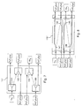
- FIG 4 shows a switch unit 15' that includes 1x2 and 2x1 optomechanical switches. It should be noted that connections that are operative under normal conditions are shown with a continuous line, while connections which are not used under normal conditions are represented with a dashed line.
- Switch unit 15' can used in place of switch unit 15 in the system of Figure 3.
- Switch unit 15' implements the required interconnection functionality and can be, for example, of the type produced by JDS FITEL, INC., 570 Heston Drive, Nepean, Ontario (CA) or of the type produced by E-TEK DYNAMICS. INC., 1885 Lundy Ave., San Jose, CA (USA).
- the input connections and the output connections of switch unit 15' are grouped on the left side and, respectively, on the right side of switch unit 15'.
- Switch unit 15' include switches 31, 33, 36, and 38 of the lx2 type and switches 32, 34, 35, and 37 of the 2x1 type.
- Switch 31 has an input that is coupled to the transmitter Tx 1 and an output that is coupled to the transmitting transponder TxT 1 ( ⁇ y ).
- Switch 32 of the 2x1 type has an input that is coupled to the output of switch 31 and an output that is coupled to the transmitting transponder TxT 2 ( ⁇ x ).
- Switch 33 of the 1x2 type has an input that is coupled to the third receiving transponder RxT 2 ( ⁇ x ) and an output that is coupled to the input of the switch 32.
- Switch 34 of the 2x1 type has an input that is coupled to the output of switch 33, as well as another input that is coupled to a receiving transponder RXT 1 ( ⁇ x ). The output of switch 34 is coupled to the receiver Rx 2 ,
- Switch 35 of the 2x1 type has an input that is coupled to the receiving transponder RxT 2 ( ⁇ y ) and an output that is coupled to the receiver Rx 1 .
- Switch 36 of the 1x2 type has an input that is coupled to the receiving transponder RxT 1 ( ⁇ y ) and an output that is coupled to the input of the switch 35.
- Switch 37 of the 2x1 type has an input that is coupled to the output of switch 36 and an output that is coupled to the transmitting transponder TxT 1 ( ⁇ y ).
- Switch 38 of the 1x2 type has an input that is coupled to the transmitter Tx 2 and an output that is coupled to the input of switch 37; the other output of switch 38 is coupled to the transmitting transponder TxT 2 ( ⁇
- Switch unit 15" includes a lithium niobate (LiNbO 3 ) integrated switching matrix, in which interconnections among input and outputs are similarly configured to the layout of the switch unit 15' of Figure 4.
- switch unit 15" includes four 1x2 switches, in which each of the 1x2 switches contains the following components: an input waveguide; a Y-shaped branching waveguide that has one input arm that is connected to input waveguide; and two output waveguides, in which each is connected to the output arms of the branching waveguide.
- the connections which are operative under normal conditions are shown with a continuous line, while connections which are not used under normal condition are represented with a dashed line.
- the switch unit 15" also has four 2x1 switches.
- Each of the four 2x1 switches includes the following components: two input waveguides; a Y-shaped branching waveguide with two input arms that are connected to the input waveguides; and an output waveguide that is connected to the output arm of the branching waveguide.
- switch unit 15" includes electrodes (not shown) that are formed on the surface of the substrate in correspondence of the Y-shaped branching waveguides and adapted to produce the switching action between the two arms of the Y.
- Switch 41 (1x2) has an input waveguide that is coupled to the transmitter Tx 1 and an output waveguide that is coupled to the transmitting transponder TxT 1 ( ⁇ x ).
- Switch 42 (2x1) has an input waveguide that is coupled to the output waveguide of switch 41 and an output waveguide that is coupled to the transmitting transponder TxT 2 ( ⁇ x ).
- Switch 43 (1x2) has an input waveguide that is coupled to the receiving transponder RXT 2 ( ⁇ x ) and an output waveguide that is coupled to the input waveguide of switch 42.
- Switch 44 (2x1) has an input waveguide that is coupled to the output waveguide of switch 43, and another input waveguide that is coupled to the receiving transponder RxT 1 ( ⁇ x ).
- the output waveguide of switch 43 is coupled to the receiver Rx 2 .
- Switch 45 (2x1) has an input waveguide that is coupled to the receiving transponder RxT 2 ( ⁇ y ) and an output waveguide that is coupled to the receiver Rx 1 .
- Switch 46 (1x2) has an input waveguide that is coupled to the receiving transponder RxT 1 ( ⁇ y ) and an output waveguide that is coupled to the second input waveguide of the switch 45.
- Switch 47 (2x1) has an input waveguide that is coupled to the output waveguide of switch 46 and an output waveguide that is coupled to the transmitting transponder TxT 1 ( ⁇ y ).
- Switch 48 (1x2) has an input waveguide that is coupled to the transmitter Tx 2 , an output waveguide that is coupled to the input waveguide of switch 47, and another output waveguide that is coupled to the transmitting transponder TxT 2 ( ⁇ y ).
- an integrated switching matrix offers several advantages over a switching matrix that employs discrete components (as with switch units 15 and 15').
- opto-mechanical switch units 15 and 15' require a larger foot print than switch unit 15"; for example, a single 2x2 opto-mechanical switch may occupy a surface of about 48x18 mm 2 , in which four switches are needed to form the switch unit 15, while the integrated switch unit 15" may occupy an area of about 4x65 mm 2 .
- the integrated switch unit 15" has response times that are lower than opto-mechanical switch units 15 and 15'.
- integrated switch limit 15" exhibits response times of about 1 ms, while opto-mechanical switch units 15 and 15' have typical response times of about 5-10 ms.
- the use of a single integrated device in place of four 2x2 switches or eight 1x2 and 2x1 switches simplifies the piloting electronic circuit. Further, the integrated switch unit 15" is less expensive than opto-mechanical switch units 15 and 15'.
- switches can be used beyond those of units 15, 15', and 15".
- these other switches which may use a discrete components switching matrix or an integrated switching matrix, may include thermo-optical switches, magneto-optical switches, liquid crystal switches, SOA (Semiconductor Optical Amplifier) switches, electro-optical switches and micro-mechanical switches (MEMS).
- thermo-optical switches magneto-optical switches
- magneto-optical switches liquid crystal switches
- SOA semiconductor Optical Amplifier
- electro-optical switches and micro-mechanical switches (MEMS).
- the node structure previously described is adapted to manage two working links on the same logical ring. However, if the client traffic pattern requires only one working link to be terminated at a node, such node can be sub-equipped; that is, fewer components can be utilized. This situation is shown in Figure 6, in which a one-link node 20j is adapted to manage a single working link on the left-hand side, shown under normal operating conditions.
- Node 20j differs from the node 20i of Figure 3 in that the transmitter Tx 2 , the receiver Rx 2 , the receiving transponder RXT 1 ( ⁇ x ) and the transmitting transponder TxT 2 ( ⁇ y ) of node 20i are absent, and in that the node 20j includes a switch unit 115 which does not utilize switches 24, 25 of switch unit 15.
- the receiving transponder RXT 2 ( ⁇ x ) is directly coupled to the input 22b of the switch 22 and the output 23d of switch 23 is directly coupled to the transmitting transponder TxT 1 ( ⁇ y ).
- the single working link that is managed by node 20j includes signals that are sent by node 20j to another node at the working wavelength ⁇ y,w on the external ring 2 as well as signals that are received by node 20j from the other node at the working wavelength ⁇ y,w on the internal ring 3. Protection wavelengths ⁇ x,p and ⁇ y,p are managed in the same way as previously described with respect to the two-link node.
- FIG. 7 shows an alternative switch unit 115' for a one-link node, which can be used in place of switch unit 115 of Figure 6.
- Switch unit 115' includes 1x2 and 2x1 optomechanical switches of the same type as those of switch unit 15' and implements the interconnection functionality that is required for node 20j, in which the unused interconnections are omitted.
- input connections and output connections of switch unit 115' are grouped on the left side and on the right side, respectively, of switch unit 115'.
- the connections, which are operative under normal conditions, are shown with a continuous line, while connections which are not used under normal conditions are represented with a dashed line.
- Switch unit 115' includes a switch 131 (1x2), a switch 132 (2x1), a switch 135 (2x1), and a switch 136 (1x2), which are equivalent to switches 31, 32, 35 and 36 of switch unit 15' ( Figure 4), respectively; however, switch unit 115' differs from switch unit 15' in that switches 33, 34, 37 and 38 of switch unit 15' are absent.
- Switch 131 of the 1x2 type has an input that is coupled to the transmitter Tx 1 and an output that is coupled to the transmitting transponder TxT 1 ( ⁇ x ).
- Switch 132 of the 2x1 type has an input that is coupled to an output of switch 131, and another input that is coupled to the receiving transponder RXT 2 ( ⁇ x ).
- the output of switch 132 is coupled to the third transmitting transponder TxT 2 ( ⁇ x ).
- Switch 135 of the 2x1 type has an input that is coupled to the receiving transponder RxT 2 ( ⁇ y ) and an output that is coupled to the receiver Rx 1 .
- Switch 136 of the 1x2 type has an input that is coupled to the receiving transponder RxT 1 ( ⁇ y ), an output that is coupled to the input of switch 135, and another output is coupled to the transmitting transponder TxT 1 ( ⁇ y ).
- FIG 8 shows an integrated optics switch unit 115" that has a similar switching architecture of switch unit 115' of Figure 7, but realized using the similar technology of switch unit 15" of Figure 5 (i.e., lithium, niobate (LiNbO 3 ) integrated circuit technology).
- Switch unit 115" includes a switch 141 (1x2), a switch 142 (2x1), a switch 145 (2x1); and a switch 146 (1x2), which perform the similar signal routing as the corresponding switches of switch unit 115' (figure 7).
- switch units 115, 115' and 115" may include the following types of switch: thermo-optical switches, magneto-optical switches, liquid crystal switches, SOA (Semiconductor Optical Amplifier) switches, electro-optical switches and micro-mechanical switches (MEMS).
- thermo-optical switches magneto-optical switches
- magneto-optical switches liquid crystal switches
- SOA semiconductor Optical Amplifier
- electro-optical switches and micro-mechanical switches (MEMS).
- MEMS micro-mechanical switches
- Network 1 ( Figure 2).
- a link between a first and a second node of the network 1 has to be established, a generic pair of first and second wavelengths ⁇ x , ⁇ y is chosen within the wavelength band.
- a working link is then set up between the two nodes by connecting the transmitter Tx 1 of the first node to the receiver Rx 2 of the second node using the first wavelength ⁇ x on the external ring 2, and by connecting the transmitter Tx 2 of the second node to the receiver Rx 1 of the first node using the second wavelength ⁇ y on the internal ring 3, on the same working arc path.
- other working links may be set up in the protection path of the two nodes, provided that the working path used by each working link is non-overlapping with other working paths that are used by other working links using the same wavelengths.
- the second wavelength ⁇ y on the external ring 2 and the first wavelength ⁇ x on the internal ring 3 are not used under normal operating conditions, but are reserved for optical protection (i.e., are reserved for use in case of failure).
- Each working link is controlled by the associated two terminating nodes.
- the two nodes at the end of the link provide the add/drop functions on working wavelengths ⁇ x,w and ⁇ y,w to/from the set of transmission wavelengths ⁇ 1 , ..., ⁇ N .
- all the required monitoring functions on the transmitted signals e.g., optical power level, channel identifier, BER performance, etc.
- the nodes that are not involved in processing signals at these working wavelengths ⁇ x,w and ⁇ y,w simply bypass the signals.
- Each node at the end of a working link using wavelengths ⁇ x,p and ⁇ y,p also control the protection wavelengths ⁇ wx,wp and ⁇ y,p ; these protection wavelengths are utilized by all the working links of the corresponding logical ring.
- the other nodes i.e., the nodes external to this logical ring
- the nodes that are not included in a logical ring i.e., nodes that do not terminate a working link on a particular logical ring
- the working link between node 20c and node 20f that utilize working wavelengths ⁇ x,w and ⁇ y,w is under control of these two nodes 20c and 20f.
- the working link between nodes 20d and 20e; which use the same wavelengths, is under control of nodes 20d and 20e.
- Each of the nodes 20c, 20d, 20e. and 20f also control the protection wavelengths ⁇ xp and ⁇ y,p associated with the corresponding logical ring to have access to the shared protection resource.
- nodes 20a and 20b cannot be part of the logical ring operating at working wavelengths ⁇ x,w , ⁇ y,w but these nodes 20a and 20b may serve as termination nodes of working links at wavelengths different from ⁇ x,w , ⁇ y,w Accordingly, nodes 20a and 20b do not perform any action on working wavelengths ⁇ x,w , ⁇ y,w and protection wavelengths ⁇ x,p , ⁇ y,p ; however, these nodes 20a and 20b may provide optical amplification on the set of transmission wavelengths ⁇ 1 , ..., ⁇ N .
- each of the nodes 20a and 20b may be required to provide functions like regeneration or monitoring on the bypassed wavelengths, in order to allow a constant performance control of the set of transmission wavelengths ⁇ 1 , ⁇ 2 , ..., ⁇ N over the entire ring network. Under failure conditions, these nodes 20a and 20b need not provide any reconfiguration of the channels that are carried by the bypassed wavelengths.
- the signal flow inside the node 20i under normal operating conditions, is now described.
- the OADM 4, 5 drop the wavelengths associated with the logical rings. All the other wavelengths may be directly bypassed to the node output without any processing.
- OADM 4 drops from the set of transmission wavelengths ⁇ 1 , ..., ⁇ N on the external ring 2 both the working and protection wavelengths ⁇ x,w , ⁇ y,p , (and possibly working and protection wavelengths of other logical rings to be managed), while OADM 5 drops from the set of transmission wavelengths ⁇ 1 , ..., ⁇ N on the internal ring 3 both the working and protection wavelengths ⁇ x,w , ⁇ y,p , ⁇ y,w (and possibly working and protection wavelengths of other logical rings).
- Wavelengths ⁇ x,w , ⁇ y,p , ⁇ y,w and ⁇ x,p are sent directly to the respective receiving transponders RXT 1 ( ⁇ x ), RxT 1 ( ⁇ y ), RXT 2 ( ⁇ y ) and RXT 2 ( ⁇ x ), in which, after electrical conversion, information related to the link (link signalling) is extracted and sent to the CPU 16 for processing, After processing, wavelengths ⁇ x,w , ⁇ y,p , ⁇ y,w and ⁇ x,p are converted back to optical signals with a new optical format.
- the working wavelength ⁇ y,w is then routed through switch unit 15 to the receiver Rx 1 , and the working wavelength ⁇ x,w is routed through switch unit 15 to the receiver Rx 2 .
- the protection wavelengths ⁇ x,p and ⁇ y,p are bypassed through switch unit 15 to the transmitting transponder TXT 2 ( ⁇ x ) and to the transmitting transponder TxT 1 ( ⁇ y ), respectively, from where they are fed to the internal ring 3 and to the external ring 2 by the respective OADM 5 and OADM 4.
- Signalling information that is carried by the protection wavelengths is left unchanged, because the protection scheme has not been evoked on the two working channels.
- Signals that are generated by the transmitter Tx 1 are routed through switch unit 15 to the transmitting transponder TxT 1 ( ⁇ x ) for transmission on the working wavelength ⁇ x,w .
- the signals that generated by the transmitter Tx 2 are routed through switch unit 15 to the transmitting transponder TxT 2 ( ⁇ y ) for transmission on the working wavelength ⁇ y,w .
- TXT 1 ( ⁇ x ), TxT 2 ( ⁇ y )
- appropriate information (link signalling, channel identifier) that is generated by CPU 16 is added (for example by using bytes k1 and k2 as recommended in the ITU-T standard) to signals on the working wavelength ⁇ x,w and the working wavelength ⁇ y,w , respectively.
- These wavelengths are then sent to the external and internal rings 2, 3 by OADMs 4, 5, respectively.
- Identical operations are performed in each receiving/transmitting module that is included in node 20i, for corresponding pairs of wavelengths that have to be managed by this node.
- failure is any event or condition that affects the transmission of signals between two node; such events or conditions may be a fiber cut, or equipment malfunction (e.g., OADM or transponder malfunction).
- Reconfiguration is performed independently for each logical ring. In particular, for each working link that is affected by the failure, reconfiguration takes place only at the pair of nodes that terminate the link, while the nodes that are interposed between these terminating nodes do not perform any action to restore the failed link.
- the associated terminating two nodes detect the failure condition (as will be more fully described below) and run the reconfiguration process by switching the transmission on the respective protection arc path, using the protection wavelengths ⁇ x,p , ⁇ y,p . That is, signals that are previously transmitted at the working wavelength ⁇ x,w on the external ring 2 are switched at the protection wavelength ⁇ x,p on the internal ring 3, while signals previously transmitted at the working wavelength ⁇ y,w on the internal ring 3 are switched at the protection wavelength ⁇ y,p on the external ring 2.
- the working link between the two nodes is consequently re-routed on the respective protection path by using the protection wavelengths ⁇ x,p , ⁇ y,p even through other nodes which are terminating other working links on the same logical ring.
- These other nodes do not perform any action resulting fi-om the reconfiguration process, as performed by the nodes terminating the failed working link, but must be aware of the presence of a signal carried by the protection wavelengths in order to know that the protection scheme has been invoked by another working link of the same logical ring. Therefore, as a consequence of the protection operations being performed on the failed working link, all the other working links of the same logical ring become unprotected.
- Figure 9 shows a situation in which a failure occurs in the ring network of Figure 2 between nodes 20a and 20b.
- nodes 20a and 20b do not perform any activity in response to the failure; because, under this scenario, these nodes 20a and 20b are not terminating nodes of a working link that is affected by the failure.
- nodes 20c and 20f An exemplary sequence of operations that is performed by nodes 20c and 20f for failure detection and corresponding signalling is now described. It is recognized that different sequences of operations may alternatively be used, without departing from the scope of the present invention; all leading to a transitory condition at the end of which nodes 20c and 20f are both reconfigured. Assuming that the failure affects only the transmission from node 20f to node 20c (along the internal ring 3), while the opposite transmission (along the external ring 2) is still operative, node 20c detects the absence of signals or a signal quality degradation (corresponding, for example, to a BER over a predetermined threshold) at the working wavelength ⁇ y,w on the receiving transponder RxT 2 ( ⁇ y ).
- a signal quality degradation corresponding, for example, to a BER over a predetermined threshold
- CPU 16 of node 20c executes instruction to reconfigure switch unit 15 (as hereinbelow described with reference to Figure 10) in order to switch the transmission (in the manner described below) on the protection path.
- node 20c sends node 20f a failure message, preferably along both the external ring 2 (in the counter-clockwise direction) and the internal ring 3 (in the clockwise direction) using the protection wavelengths ⁇ y,p and ⁇ y,p , to inform node 20f of the condition.
- node 20f receives the message from both the external ring 2 and the internal ring 3 (for example at the protection wavelengths ⁇ x,p and ⁇ x,p ); in response to the message, node 20f performs the reconfiguration of switch unit 15 (as shown in Figure 13) to switch the transmission onto the protection path.
- node 20f detects the failure.
- the first node as between nodes 20c and 20f that detects the absence of signals or of a signal quality degradation sends the other node the failure message (preferably along both the external ring 2 and the internal ring 3 by using the protection wavelengths ⁇ y,p and ⁇ y,p ).
- This first node subsequently operates a reconfiguration of its switch unit 15.
- the other node is alerted to the presence of a failure in the considered link by detecting the failure itself or by receiving the failure message from the first node (and only from one direction, in the preferred case of the bidirectional message transmission). In response, this other node sends a failure message back to the first node and operates to initiate a reconfiguration of its switch unit 15.
- Nodes 20d and 20e which, in the example of Figure 2, are the termination nodes of another working link in the same logical ring, are informed of the changed condition by checking the status of the channel that is carried by the protection wavelengths (i.e., by reading the failure message); consequently, these nodes 20d and 20e inhibit their protection mechanism.
- Figure 10 shows the situation in which a failure occurs on a working link, which is defined by node 20i (together with a further node not shown); that is, a failure on the left-hand side of node 20i.
- Node 20i is informed of the failure condition by detecting, at the receiving transponder RxT 2 ( ⁇ y ), the absence of signals, or a signal quality degradation (like a BER over a predetermined threshold), or by receiving a failure message (as previously described).
- CPU 16 consequently generates an appropriate failure message to be sent to the other terminating node of the working link, preferably along both the external ring 2 and the internal ring 3.
- CPU 16 preferably sends this failure message to the transmitting transponder TxT 1 ( ⁇ y ) for transmission at the protection wavelength ⁇ y,p and to the transmitting transponder TxT 2 ( ⁇ x ) for transmission at the protection wavelengths ⁇ x,p .
- CPU 16 subsequently initiates reconfiguration of switch unit 15, reconfiguring switches 22 and 23 from the bypass status to the switched status in order to avoid the failed working path by re-routing the transmission onto the protection path.
- the transmitter Tx 1 is connected to the transmitting transponder TXT 2 ( ⁇ x ), and the corresponding signals are then sent on the internal ring 3 in the clockwise direction.
- the receiver Rx 1 is connected to the receiving transponder RxT 1 ( ⁇ y ).
- the signals are then received from the external ring 2 in counter-clockwise direction. If the affected node includes a switch unit 15' (1x2 and 2x1 switches) or a switch unit 15" (integrated optics) in place of switch unit 15 (2x2 switches), the reconfigured status of the corresponding switch unit is as shown in Figure 11 and in Figure 12, respectively.
- the node at the other end of the affected link performs the same operations, after receiving a failure message from the other node, or after detecting the absence of signals or a signal quality degradation at the receiving transponder RxT 1 ( ⁇ x ).
- the working link between the two nodes is consequently re-routed to the protection path associated with the working link.
- Both the reconfigured nodes also update the signalling information (generated by the respective CPUs and added to the transmitted signals in the respective transmitting transponders TxTs) that is carried by the protection wavelengths ⁇ x,p , ⁇ y,p in order to inform all the other nodes on the same logical ring that the shared resource is at present used by the two affected nodes.
- both the nodes of the affected link can be restored to the normal operative condition of Figure 3, thus releasing the shared protection resource.
- the described protection mechanism operates independently for each module 6.
- Figures 13-15 show the situation in which a failure occurs on the right-hand side of the node 20i.
- the reconfiguration process is similar to that of the left-hand side failure, and thus, is not further described.
- the architecture of the nodes may be arranged so that, in the absence of failures, protection wavelengths ⁇ x,p on the internal ring 3 and ⁇ y,p on the external ring 2 may be used to transport low-priority traffic in the same direction as the other wavelengths on 5 the same ring.
Priority Applications (1)
| Application Number | Priority Date | Filing Date | Title |
|---|---|---|---|
| EP20000305519 EP1075105B1 (de) | 1999-07-01 | 2000-06-30 | Selbstgeschütztes optisches Kommunikationsringnetzwerk |
Applications Claiming Priority (3)
| Application Number | Priority Date | Filing Date | Title |
|---|---|---|---|
| EP99112552A EP1065822A1 (de) | 1999-07-01 | 1999-07-01 | Selbstgeschützes optisches Kommunikationsringnetwerk |
| EP99112552 | 1999-07-01 | ||
| EP20000305519 EP1075105B1 (de) | 1999-07-01 | 2000-06-30 | Selbstgeschütztes optisches Kommunikationsringnetzwerk |
Publications (2)
| Publication Number | Publication Date |
|---|---|
| EP1075105A1 true EP1075105A1 (de) | 2001-02-07 |
| EP1075105B1 EP1075105B1 (de) | 2005-11-30 |
Family
ID=26073216
Family Applications (1)
| Application Number | Title | Priority Date | Filing Date |
|---|---|---|---|
| EP20000305519 Expired - Lifetime EP1075105B1 (de) | 1999-07-01 | 2000-06-30 | Selbstgeschütztes optisches Kommunikationsringnetzwerk |
Country Status (1)
| Country | Link |
|---|---|
| EP (1) | EP1075105B1 (de) |
Cited By (2)
| Publication number | Priority date | Publication date | Assignee | Title |
|---|---|---|---|---|
| WO2002073855A2 (de) * | 2001-03-12 | 2002-09-19 | Adva Ag Optical Networking | Selbstheilende ringstruktur zur optischen nachrichtenübertragung im wellenlängenmultiplex und add/drop-multiplexer hierfür |
| EP2385642A1 (de) | 2010-05-07 | 2011-11-09 | ADVA AG Optical Networking | Verfahren zur Bereitstellung von Schutz gegen Verbindungsfehler in einem optischen Kommunikationsnetzwerk |
Citations (2)
| Publication number | Priority date | Publication date | Assignee | Title |
|---|---|---|---|---|
| EP0729247A2 (de) * | 1995-02-22 | 1996-08-28 | Deutsche Telekom AG | Verfahren und Anordnung zur optimalen Nutzung der Übertragungskapazität in synchronen bidirektionalen Ringnetzen |
| US5647035A (en) * | 1994-12-09 | 1997-07-08 | Cselt- Centro Studi E Laboratori Telecomunicazioni S.P.A. | Ring network communication structure on an optical carrier and reconfigurable node for said structure |
-
2000
- 2000-06-30 EP EP20000305519 patent/EP1075105B1/de not_active Expired - Lifetime
Patent Citations (2)
| Publication number | Priority date | Publication date | Assignee | Title |
|---|---|---|---|---|
| US5647035A (en) * | 1994-12-09 | 1997-07-08 | Cselt- Centro Studi E Laboratori Telecomunicazioni S.P.A. | Ring network communication structure on an optical carrier and reconfigurable node for said structure |
| EP0729247A2 (de) * | 1995-02-22 | 1996-08-28 | Deutsche Telekom AG | Verfahren und Anordnung zur optimalen Nutzung der Übertragungskapazität in synchronen bidirektionalen Ringnetzen |
Cited By (4)
| Publication number | Priority date | Publication date | Assignee | Title |
|---|---|---|---|---|
| WO2002073855A2 (de) * | 2001-03-12 | 2002-09-19 | Adva Ag Optical Networking | Selbstheilende ringstruktur zur optischen nachrichtenübertragung im wellenlängenmultiplex und add/drop-multiplexer hierfür |
| WO2002073855A3 (de) * | 2001-03-12 | 2002-12-27 | Adva Ag | Selbstheilende ringstruktur zur optischen nachrichtenübertragung im wellenlängenmultiplex und add/drop-multiplexer hierfür |
| EP2385642A1 (de) | 2010-05-07 | 2011-11-09 | ADVA AG Optical Networking | Verfahren zur Bereitstellung von Schutz gegen Verbindungsfehler in einem optischen Kommunikationsnetzwerk |
| US9660758B2 (en) | 2010-05-07 | 2017-05-23 | Adva Optical Newtorking Se | Method for providing protection in an optical communication network against connection failures |
Also Published As
| Publication number | Publication date |
|---|---|
| EP1075105B1 (de) | 2005-11-30 |
Similar Documents
| Publication | Publication Date | Title |
|---|---|---|
| US7072580B2 (en) | Autoprotected optical communication ring network | |
| US6973267B1 (en) | Autoprotected optical communication ring network | |
| US6046833A (en) | Method and apparatus for operation, protection, and restoration of heterogeneous optical communication networks | |
| US5986783A (en) | Method and apparatus for operation, protection, and restoration of heterogeneous optical communication networks | |
| EP0848873B1 (de) | Optisches uebertragungssystem | |
| JP3008260B2 (ja) | 光伝送路のリングネットワーク通信構造とその構造用の再構成可能ノード | |
| EP1360790B1 (de) | Optische übertragungssysteme mit optischen schutzsystemen, vorrichtungen und verfahren | |
| EP2385642B1 (de) | Verfahren zur Bereitstellung von Schutz gegen Verbindungsfehler in einem optischen Kommunikationsnetzwerk | |
| US6839514B1 (en) | Method and apparatus for operation, protection, and restoration of heterogeneous optical communication networks | |
| WO1998047039A9 (en) | Method and apparatus for operation, protection, and restoration of heterogeneous optical communication networks | |
| AU2001292558A1 (en) | Optical transmission systems including optical protection systems, apparatuses, and methods | |
| CA2318046A1 (en) | Self-healing optical network | |
| CA2395303A1 (en) | Two-fiber interconnected ring architecture | |
| CA2394599A1 (en) | Four-fiber ring optical cross-connect system using 4x4 switch matrices | |
| US6061482A (en) | Channel layered optical cross-connect restoration system | |
| EP0928082B1 (de) | Verfahren und Vorrichtung für optisch transparente Übertragung in einem bidirektionalen Ringnetz mit zwei Fasern, Selbstschutz und Niederprioritätsverwaltung | |
| EP1075105B1 (de) | Selbstgeschütztes optisches Kommunikationsringnetzwerk | |
| EP1065822A1 (de) | Selbstgeschützes optisches Kommunikationsringnetwerk | |
| US7400828B1 (en) | Fault protection in networks | |
| EP1354439A2 (de) | Optisches übertragungsnetzwerk und knoten zur herstellung einem derartigen netzwerk |
Legal Events
| Date | Code | Title | Description |
|---|---|---|---|
| PUAI | Public reference made under article 153(3) epc to a published international application that has entered the european phase |
Free format text: ORIGINAL CODE: 0009012 |
|
| AK | Designated contracting states |
Kind code of ref document: A1 Designated state(s): DE FR GB IT NL |
|
| AX | Request for extension of the european patent |
Free format text: AL;LT;LV;MK;RO;SI |
|
| 17P | Request for examination filed |
Effective date: 20010802 |
|
| AKX | Designation fees paid |
Free format text: DE FR GB IT NL |
|
| 17Q | First examination report despatched |
Effective date: 20040504 |
|
| GRAP | Despatch of communication of intention to grant a patent |
Free format text: ORIGINAL CODE: EPIDOSNIGR1 |
|
| GRAS | Grant fee paid |
Free format text: ORIGINAL CODE: EPIDOSNIGR3 |
|
| RBV | Designated contracting states (corrected) |
Designated state(s): DE FR GB IT NL |
|
| GRAA | (expected) grant |
Free format text: ORIGINAL CODE: 0009210 |
|
| AK | Designated contracting states |
Kind code of ref document: B1 Designated state(s): DE FR GB IT NL |
|
| PG25 | Lapsed in a contracting state [announced via postgrant information from national office to epo] |
Ref country code: IT Free format text: LAPSE BECAUSE OF FAILURE TO SUBMIT A TRANSLATION OF THE DESCRIPTION OR TO PAY THE FEE WITHIN THE PRESCRIBED TIME-LIMIT;WARNING: LAPSES OF ITALIAN PATENTS WITH EFFECTIVE DATE BEFORE 2007 MAY HAVE OCCURRED AT ANY TIME BEFORE 2007. THE CORRECT EFFECTIVE DATE MAY BE DIFFERENT FROM THE ONE RECORDED. Effective date: 20051130 Ref country code: NL Free format text: LAPSE BECAUSE OF FAILURE TO SUBMIT A TRANSLATION OF THE DESCRIPTION OR TO PAY THE FEE WITHIN THE PRESCRIBED TIME-LIMIT Effective date: 20051130 |
|
| REG | Reference to a national code |
Ref country code: GB Ref legal event code: FG4D |
|
| REF | Corresponds to: |
Ref document number: 60024366 Country of ref document: DE Date of ref document: 20060105 Kind code of ref document: P |
|
| NLV1 | Nl: lapsed or annulled due to failure to fulfill the requirements of art. 29p and 29m of the patents act | ||
| ET | Fr: translation filed | ||
| PLBE | No opposition filed within time limit |
Free format text: ORIGINAL CODE: 0009261 |
|
| STAA | Information on the status of an ep patent application or granted ep patent |
Free format text: STATUS: NO OPPOSITION FILED WITHIN TIME LIMIT |
|
| 26N | No opposition filed |
Effective date: 20060831 |
|
| REG | Reference to a national code |
Ref country code: FR Ref legal event code: PLFP Year of fee payment: 16 |
|
| REG | Reference to a national code |
Ref country code: FR Ref legal event code: PLFP Year of fee payment: 17 |
|
| REG | Reference to a national code |
Ref country code: FR Ref legal event code: PLFP Year of fee payment: 18 |
|
| REG | Reference to a national code |
Ref country code: FR Ref legal event code: PLFP Year of fee payment: 19 |
|
| PGFP | Annual fee paid to national office [announced via postgrant information from national office to epo] |
Ref country code: FR Payment date: 20190625 Year of fee payment: 20 |
|
| PGFP | Annual fee paid to national office [announced via postgrant information from national office to epo] |
Ref country code: GB Payment date: 20190627 Year of fee payment: 20 Ref country code: DE Payment date: 20190627 Year of fee payment: 20 |
|
| REG | Reference to a national code |
Ref country code: DE Ref legal event code: R071 Ref document number: 60024366 Country of ref document: DE |
|
| REG | Reference to a national code |
Ref country code: GB Ref legal event code: PE20 Expiry date: 20200629 |
|
| PG25 | Lapsed in a contracting state [announced via postgrant information from national office to epo] |
Ref country code: GB Free format text: LAPSE BECAUSE OF EXPIRATION OF PROTECTION Effective date: 20200629 |