EP1075090A2 - A CDMA demodulating method and demodulator - Google Patents
A CDMA demodulating method and demodulator Download PDFInfo
- Publication number
- EP1075090A2 EP1075090A2 EP00305881A EP00305881A EP1075090A2 EP 1075090 A2 EP1075090 A2 EP 1075090A2 EP 00305881 A EP00305881 A EP 00305881A EP 00305881 A EP00305881 A EP 00305881A EP 1075090 A2 EP1075090 A2 EP 1075090A2
- Authority
- EP
- European Patent Office
- Prior art keywords
- values
- memory
- codes
- unit
- path
- Prior art date
- Legal status (The legal status is an assumption and is not a legal conclusion. Google has not performed a legal analysis and makes no representation as to the accuracy of the status listed.)
- Granted
Links
Images




Classifications
-
- H—ELECTRICITY
- H04—ELECTRIC COMMUNICATION TECHNIQUE
- H04B—TRANSMISSION
- H04B1/00—Details of transmission systems, not covered by a single one of groups H04B3/00 - H04B13/00; Details of transmission systems not characterised by the medium used for transmission
- H04B1/69—Spread spectrum techniques
- H04B1/707—Spread spectrum techniques using direct sequence modulation
- H04B1/7097—Interference-related aspects
- H04B1/711—Interference-related aspects the interference being multi-path interference
Definitions
- the present invention relates to a code division multiple access (hereinafter referred to as CDMA) demodulating method and demodulator, and more particularly, to a CDMA demodulating method and demodulator, in which the architectural complexity of hardware is reduced so that various services may be provided only by software download.
- CDMA code division multiple access
- a CDMA receiver which receives a CDMA signal after it has passed through a wireless channel
- signal components having different delays and amplitudes are added to the CDMA signal.
- PN codes and walsh codes are generated and multiplied with a received CDMA signal.
- weighting values are given to signals after they have been multiplied by the PN codes, the weighted signals are phase adjusted, and the resultant signals are summed.
- FIG. 1 illustrates a block diagram of the structure of a conventional CDMA demodulator.
- the conventional CDMA demodulator includes as many fingers as the number of multi-paths to be considered, and thereby processes the received CDMA signal by generating PN codes and traffic walsh codes, which vary according to the degree of delay of each path.
- a number (N) of PN-codes generators and traffic walsh codes-generators must operate simultaneously and consecutively with respect to a number (N) of the multi-paths.
- N the number of the multi-paths.
- the traffic walsh codes-generator operates when the traffic walsh codes of only one period are generated, it is necessary to reduce the architectural complexity of the hardware and the power consumption.
- a CDMA demodulating method comprises the step of (a) sequentially-storing all input data, which are over-sampled by M-fold and go through a number (N) of paths, in a predetermined first memory, where M and N are predetermined positive integers; (b) generating PN codes for each of the N paths and storing the PN codes in a predetermined second memory; (c) generating and sequentially-storing traffic walsh codes of one period, which correspond to a processing gain L, in a predetermined third memory; (d) multiplying a complex-conjugated value with one of the values stored in the first memory and one of the values stored in the second memory; (e) performing a control operation for storing the PN codes in a predetermined address of the second memory and a control operation for outputting data for each of the N paths from the first, second, and third memories; (f) multiplying the resultant value of the step (d) with the traffic
- a CDMA demodulating method comprises the steps of: (a) sequentially-storing all input data, which are over-sampled by M-fold and go through a number (N) of paths, in a predetermined first memory, where M and N are predetermined positive integers; (b) generating PN codes for each of the N paths; (c) storing the PN codes in a predetermined second memory; (d) complex-conjugating the PN codes; (e) checking whether traffic walsh codes of all one period are stored in a predetermined third memory; (f) sequentially-storing the traffic walsh codes by generating the traffic walsh codes, which correspond to a first access path, until traffic walsh codes of all one period, which corresponds to a processing gain L, are stored in a case where traffic walsh codes of all one period are not stored in the third memory; (g) omitting the performance of the step (f) in
- the CDMA demodulator comprises: a first memory for sequentially-storing input data, which are over-sampled by M-fold, where M is a predetermined positive integer; a PN codes-generating unit for generating different PN codes for each path; a second memory for sequentially-storing the PN codes output from the PN codes-generating unit; a first complex-conjugating unit for complex-conjugating the PN codes by inputting from the second memory the PN codes generated by the PN codes-generating unit; a first multiplying unit for multiplying a complex-conjugated value of one of the values stored in the second memory with one of the values stored in the first memory; a controlling unit for performing a control operation for storing the PN codes generated in the PN codes-generating unit in the same address as the modulo K-operated result, in the order in which the PN codes are received from the second memory and for performing
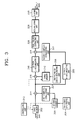
- FIG. 3 is a block diagram of the structure of a CDMA demodulator according to a preferred embodiment of the present invention in which the CDMA demodulating method according to the present invention is implemented.
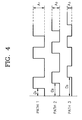
- FIG. 4 illustrates the concept of a received CDMA signal so as to explain the CDMA demodulating method according to the present invention
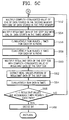
- FIGS. 5A through 5C are flowcharts illustrating the main steps of the CDMA demodulating method according to the preferred embodiment of the present invention.
- FIG. 5 will be referred to as occasion demands.
- the CDMA demodulator includes a first memory 302, a PN-codes generating unit 304, a second memory 306, a first complex-conjugating unit 307, a traffic walsh codes-generating unit 308, a third memory 310, a controlling unit 312, a first multiplying unit 314, a second multiplying unit 316, an N-path L-accumulating unit 318, an N-path X-accumulating unit 320, a second complex-conjugating unit 322, a third multiplying unit 324, a real-values extracting unit 326, an accumulating unit 328, and a slicing unit 330.
- a CDMA transmitter Before transmitting a CDMA signal to different users a CDMA transmitter (not shown) multiplies a signal by specific traffic walsh codes and then, PN codes.
- a CDMA receiver restores specific user's data bits by multiplying the received CDMA signal by walsh codes, which are assigned to the specific user, and then, PN codes.
- the CDMA signal goes through multi-path channels, the CDMA signal has different delayed quantities D 1 , D 2 , and D 3 and amplitudes A 1 , A 2 , and A 3 with respect to the paths, as shown in FIG. 4. That is, a received CDMA signal is expressed by the sum of a plurality of signals.
- the plurality of signals having different delayed quantities for example, D 1 , D 2 , and D 3 and amplitudes A 1 , A 2 , and A 3 , as shown in FIG. 4 are added to the received CDMA signal after going through wireless channels, and the received CDMA signal is input to the CDMA demodulator.
- the CDMA demodulator uses several identical signals for effectively-restoring data.
- the CDMA demodulator generates walsh codes, which coincide with the delay of each path, and PN codes, and then, multiplies the walsh codes and the PN codes with the received CDMA signal. Next, weighting values are given to signals after they have been multiplied by the PN codes, the weighted signals are phase adjusted, and the resultant signals are summed.
- input data which are over-sampled by M-fold, are sequentially-stored in the first memory 302 (step 502).
- the first memory 302 is formed to have a size big enough to store an input signal having an over-sampling rate M.
- the first memory 302 performs a store operation continuously until all signals, which go through a number (N) of paths, are stored.
- the PN-codes generating unit 304 After that, the PN-codes generating unit 304 generates PN codes, which correspond to a first excess path (step 504) and stores the PN codes in the second memory 306 (step 506).
- K is a positive integer
- the size K of the second memory 306 is decided considering a maximum excess delay to be considered in the CDMA receiver.
- the PN codes generated in the PN-codes generating unit 304 are stored in the same address as a modulo K-operated result, in the order in which the PN codes are received from the second memory 306.
- the phases of the PN codes, which are formed in the PN-codes generating unit 304, must coincide with the phases of the PN codes of the signal received from the first access path of the multi-paths to be processed in the CDMA demodulator.
- the PN codes, which are generated by the PN-codes generating unit 304 and stored in the second memory 306, are output and then, complex-conjugated by the first complex-conjugating unit 307.
- traffic walsh codes of all one period are stored in the third memory 310 (step 508).
- the traffic walsh codes-generating unit 308 generates traffic walsh codes, which correspond to the first access path (step 510), and sequentially stores the traffic walsh codes in the third memory 310 until traffic walsh codes of all one period, which corresponds to a processing gain L, are stored in the third memory 310 (step 512).
- steps 510 through 512 are omitted.
- the phases of the codes generated in the traffic walsh codes-generating unit 308 are identical with those of traffic walsh codes of a signal received from the first access path of the multi- paths to be processed in the CDMA receiver.
- the size of the third memory 310 is decided considering the processing gain L.
- the first multiplying unit 314 multiplies a complex-conjugated value of one of the values stored in the second memory 306 with one of the values stored in the first memory 302 (step 514).
- the controlling unit 312 performs a control operation for storing the PN codes generated in the PN codes-generating unit 304 in the same address as the modulo K-operated result, in the order in which the PN codes are received from the second memory 306, and a control operation for outputting data for each path from the first, second, and third memories 302, 306, and 310.
- the second multiplying unit 316 multiplies a value output from the first multiplying unit 314 with the traffic walsh codes corresponding to the first access path of data stored in the third memory 310 (step 516).
- the N-path L-accumulating unit 318 cumulatively sums the output data of the second multiplying unit 316 L times for each of the N multi-paths to be processed, where L corresponds to the processing gain.
- the N-path L-accumulating unit 318 cumulatively sums values L times for each of N paths (step 518).
- values corresponding to the first path, second path, and N-th path are sequentially-input to the N-path L-accumulating unit 318.
- the N-path L-accumulating unit 318 cumulatively sums the values, which are sequentially-input and correspond to each path, independently for each path L times.
- the N-path X-accumulating unit 320 cumulatively sums the data output from the first multiplying unit 314 X times for each of N paths (step 520).
- the N-path X-accumulating unit 320 independently accumulates former X values output from the first multiplying unit 314 based on time when L resultant values-accumulation of the N-path L-accumulating unit 318 for each path is completed. Values, which correspond to the first path, second path, and up to last (N-th) path, are sequentially-output from the first multiplying unit 314. Accordingly, this process is sequentially and repeatedly performed with respect to each path.
- the N-path X-accumulating unit 320 cumulatively sums X times the values, which are sequentially-input and correspond to each path, for each path independently. When X resultant values-accumulation on each path is completed, the N-path X-accumulating unit independently accumulates the former X values output from the first multiplying unit 314 based on time when the next L resultant values-accumulation of the N-path L-accumulating unit 318 with respect to each path is completed.
- step 524 it is checked whether the steps 514 through 520 have been performed N times, and the steps 514 through 520 are performed with respect to the last N-th path by repeatedly-performing the steps.
- step 522 Only when a multiplication operation is performed from the time when L resultant values-accumulation is completed, it is possible to multiply values output from the N-path X-accumulating unit 320 with the complex-conjugated value by the second complex-conjugating unit 322 in the third multiplying unit 324. Accordingly, it is determined whether L-1 resultant values are accumulated (step 522), and the L-1 resultant values-accumulation with respect to the N number of paths is performed. Therefore, the step 522 is performed until a number (L-1) of values on each path are accumulated in the N-path L-accumulating unit 318 by checking whether the L-1 resultant values-accumulation is performed with respect to each path (step 522).
- step 522 In which checking is performed whether the L-1 resultant values-accumulation is performed with respect to each path, that the number (L-1) of values are accumulated on each path in the N-path L-accumulating unit 318, the steps shown in FIG. 5B are performed.
- Each of the steps 540, 542, 544, 546, 548, 550, 552, 554, 556, and 558 are substantially identical with those described above, Thus, a description thereof will be omitted.
- the third multiplying unit 324 multiplies the output values of the second complex-conjugating unit 322 with the output values of the N-path L-accumulating unit 318 (step 560). Accordingly, the number (N) of values are sequentially and independently by path input to the third multiplying unit 324, and the third multiplying unit 324 sequentially-outputs the number (N) of independent values by path.
- the real-values extracting unit 326 for sequentially and for each path independently inputting N data values output from the third multiplying unit 324, and for sequentially-outputting the N independent values for each path, and takes only real values (step 562).
- the third multiplying unit 324 and real-values extracting unit 326 it is possible for the third multiplying unit 324 and real-values extracting unit 326 to be performed as one step by combining their functions.
- the accumulating unit 328 accumulates data sequentially-output from the real-values extracting unit 326 by cumulatively summing the data sequentially-output from the real-values extracting unit 326 N times (step 564).
- the slicing unit 330 decides bit values based on logic values identified by identifying the logic values of the output of the real-values extracting unit 326 (step 568).
- the CDMA demodulating method according to the present invention only one PN-codes generator can be used regardless of the number of multi-paths to be considered in the CDMA receiver. Also, the CDMA demodulating method according to the present invention can remarkably reduce the number of necessary down-samplers, and additional means for controlling a buffer is unnecessary.
- the present invention can reduce the complexity of system and the power consumption by reducing the number of necessary devices. Also, according to the CDMA demodulating method of the present invention, since there is no work simultaneously-performed, the present invention is suitable for downloading by software and performing a demodulation operation in a processor.
- the CDMA demodulating method according to the present invention can be realized as a program in the integrated circuit (IC) of a digital signal processor (DSP).
- IC integrated circuit
- DSP digital signal processor
- the present invention can reduce the architectural complexity of hardware and is suitable for downloading by software and performing a demodulation operation in a processor.
Landscapes
- Engineering & Computer Science (AREA)
- Computer Networks & Wireless Communication (AREA)
- Signal Processing (AREA)
- Mobile Radio Communication Systems (AREA)
Abstract
Description
Claims (8)
- A code division multiple access (CDMA) demodulating method performed in a CDMA system, comprising the steps of:(a) sequentially-storing all input data, which are over-sampled by M-fold and go through a N number of paths, in a predetermined first memory, where M and N are predetermined positive integers;(b) generating PN codes for each of the N paths and storing the PN codes in a predetermined second memory;(c) generating and sequentially-storing traffic walsh codes of one period, which correspond to a processing gain L, in a predetermined third memory;(d) multiplying a complex-conjugated value with one of values stored in the first memory and one of values stored in the second memory;(e) performing a control operation for storing the PN codes in a predetermined address of the second memory and a control operation for outputting data for each of the N paths from the first, second, and third memories;(f) multiplying the resultant value of the step (d) with the traffic walsh codes of a corresponding path of data stored in the third memory;(g) cumulatively summing the resultant value of the step (f) L times for each of the N multi-paths to be processed, where L corresponds to the processing gain;(h) complex-conjugating the result value of the step (d) by cumulatively adding the resultant value of the step (d) X times for each of the N multi-paths to be processed, where X corresponds to the data bit number of the walsh codes;(i) obtaining a number (N) of data by inputting the resultant value of the step (f) and the resultant value of the step (h) and multiplying the resultant value of the step (f) with the resultant value of the step (h);(j) sequentially-obtaining a number (N) of values by sequentially-inputting the number (N) of data obtained in the step (i) and taking only real values;(k) cumulatively summing the data obtained in the step (i) N times; and(l) deciding bit values based on logic values identified by identifying the logic values of the result of the step (k).
- A code division multiple access (CDMA) demodulating method performed in a CDMA system, comprising the steps of:(a) sequentially-storing all input data, which are over-sampled by M-fold and go through a number (N) of paths, in a predetermined first memory, where M and N are predetermined positive integers;(b) generating PN codes for each of the N paths;(c) storing the PN codes in a predetermined second memory;(d) complex-conjugating the PN codes;(e) checking whether traffic walsh codes of all one period are stored in a predetermined third memory;(f) sequentially-storing the traffic walsh codes by generating the traffic walsh codes, which correspond to a first access path, until traffic walsh codes of all one period, which corresponds to a processing gain L, are stored in a case where traffic walsh codes of all one period are not stored in the third memory;(g) omitting the performance of the step (f) in a case where traffic walsh codes of all one period are stored in the third memory;(h) multiplying a complex-conjugated value with one of the values stored in the second memory and one of the values stored in the first memory;(i) performing a control operation for storing the PN codes in a predetermined address of the second memory and a control operation for outputting data for each of the N paths from the first, second, and third memories;(j) multiplying the resultant value of the step (h) with the traffic walsh codes of a corresponding path of data stored in the third memory;(k) cumulatively summing the resultant value of the step (j) L times for each of the N multi-paths to be processed, where L corresponds to the processing gain;(l) cumulatively summing the resultant value of the step (h) X times for each of the multi-paths to be processed, where X corresponds to the data bit number of the walsh codes;(m) checking whether L-1 resultant values are accumulated;(n) checking whether N resultant values are accumulated when it is determined that the L-1 resultant values are not accumulated in the step (m);(o) repeatedly-performing the steps (j) through (n) with respect to the values by outputting the values, which correspond to a next path in the first, second, third memories when it is determined that the N resultant values are not accumulated in the step (n);(p) performing the steps (a) through (o) when it is determined that work with respect to the N-th path is completed in the step (n);(q) performing the steps (a) through (l) when it is determined that the L-1 resultant values are accumulated in the step (m);(r) multiplying the complex-conjugated values of the resultant value of the step (l) with the resultant value of the step (k);(s) sequentially-obtaining a number (N) of values by sequentially-inputting the number (N) of data obtained in the step (r) and taking only real values;(t) cumulatively summing the data obtained in the step (s) N times; and(u) deciding bit values based on logic values identified by identifying the logic values of the result of the step (t).
- The CDMA demodulating method according to claim 2, wherein the step (i) comprises the steps of:performing a control operation for storing the PN codes generated in a PN codes-generating unit in the same address as the modulo K-operated result, in the order in which the PN codes are received from the second memory, when the address size of the memory is a predetermined positive integer K; andperforming a control operation for outputting data for each of the N paths from the first, second, and third memories.
- A code division multiple access (CDMA) demodulator used in a CDMA system, comprising:a first memory (302) for sequentially-storing input data, which are over-sampled by M-fold, where M is a predetermined positive integer;a PN codes-generating unit (304) for generating different PN codes for each path;a second memory (306) for sequentially-storing the PN codes output from the PN codes-generating unit (304);a first complex-conjugating unit (307) for complex-conjugating the PN codes by inputting from the second memory (306) the PN codes generated by the PN codes-generating unit (304);a first multiplying unit (314) for multiplying a complex-conjugated value of one of the values stored in the second memory (306) with one of values stored in the first memory (302);a controlling unit (312) for performing a control operation for storing the PN codes generated in the PN codes-generating unit (304) in the same address as the modulo K-operated result, in the order in which the PN codes are received by the second memory (306) and for performing a control operation for outputting data for each path from the first, second, and third memories (302,306,310);a second multiplying unit (316) for multiplying a value output from the first multiplying unit (314) with the traffic walsh codes of a corresponding path of data stored in the third memory (310);a N-path L-accumulating unit (318) for cumulatively-summing the output data of the second multiplying unit L times for each of the N multi-paths to be processed, where L corresponds to the processing gain;a N-path X-accumulating unit (320) for cumulatively-summing the data output from the first multiplying unit (314) X times for each of the N multi-paths to be processed, where X corresponds to the data bit number of the walsh codes;a second complex-conjugating unit (322) for complex-conjugating the output values of the N-path X-accumulating unit (320) by inputting the output values of the N-path X-accumulating unit (320);a third multiplying unit (324) for multiplying the output values of the second complex-conjugating unit (322) with the output values of the N-path L-accumulating unit (318);a real-values extracting unit (326) for sequentially and for each path independently inputting N data values output from the third multiplying unit (324), and for sequentially-outputting the N independent values for each path, and taking only real values;an accumulating unit (328) for cumulatively-summing the data sequentially-output from the real-values extracting unit (326) N times; and,a bit-deciding unit (330) for deciding bit values based on logic values identified by identifying the logic values of the output of the accumulating unit (328).
- The CDMA demodulator according to claim 4, wherein the first memory (302) is formed to have a size big enough to store an input signal having an over-sampling rate M.
- The CDMA demodulator according to claim 4 or 5, wherein the size of the second memory (306) is decided considering a maximum excess delay to be considered in the CDMA receiver when the size of the second memory is K.
- The CDMA demodulator according to any of claims 4 to 6, wherein the controlling unit (312) performs a control operation for storing the PN codes generated in the PN codes-generating unit (304) in the same address as the modulo K-operated result, in the order in which the PN codes of the second memory (306) are generated, and a control operation for outputting data for each path from the first, second, and third memories (302,306,310).
- The CDMA demodulator according to any of claims 4 to 7, wherein the size of the third memory (310) is large enough to store the data corresponding to the processing gain L.
Applications Claiming Priority (2)
| Application Number | Priority Date | Filing Date | Title |
|---|---|---|---|
| KR9928205 | 1999-07-13 | ||
| KR10-1999-0028205A KR100450791B1 (en) | 1999-07-13 | 1999-07-13 | CDMA demodulating method and demodulator |
Publications (3)
| Publication Number | Publication Date |
|---|---|
| EP1075090A2 true EP1075090A2 (en) | 2001-02-07 |
| EP1075090A3 EP1075090A3 (en) | 2003-05-21 |
| EP1075090B1 EP1075090B1 (en) | 2006-08-30 |
Family
ID=37026591
Family Applications (1)
| Application Number | Title | Priority Date | Filing Date |
|---|---|---|---|
| EP20000305881 Expired - Lifetime EP1075090B1 (en) | 1999-07-13 | 2000-07-12 | A CDMA demodulating method and demodulator |
Country Status (6)
| Country | Link |
|---|---|
| US (1) | US6480527B1 (en) |
| EP (1) | EP1075090B1 (en) |
| JP (1) | JP4480237B2 (en) |
| KR (1) | KR100450791B1 (en) |
| CN (1) | CN1161904C (en) |
| DE (1) | DE60030371T2 (en) |
Cited By (4)
| Publication number | Priority date | Publication date | Assignee | Title |
|---|---|---|---|---|
| WO2004019510A1 (en) * | 2002-08-21 | 2004-03-04 | Koninklijke Philips Electronics N.V. | Delay line for multiple propagation paths reception |
| WO2006078233A1 (en) * | 2005-01-14 | 2006-07-27 | Thomson Licensing | Ram-based scrambling code generator for cdma |
| US8059776B2 (en) | 2005-01-14 | 2011-11-15 | Thomson Licensing | Method and system for sub-chip resolution for secondary cell search |
| US8442094B2 (en) | 2005-01-14 | 2013-05-14 | Thomson Licensing | Cell search using rake searcher to perform scrambling code determination |
Families Citing this family (6)
| Publication number | Priority date | Publication date | Assignee | Title |
|---|---|---|---|---|
| KR20020084464A (en) * | 2001-05-02 | 2002-11-09 | 엘지전자 주식회사 | CDMA demodulator system |
| US6924620B2 (en) * | 2002-07-25 | 2005-08-02 | Milwaukee Electric Tool Corporation | Battery, battery charger, electrical system and method of charging a battery |
| KR100869505B1 (en) * | 2004-02-06 | 2008-11-21 | 엘지전자 주식회사 | Multipath Navigation Apparatus and Method |
| BRPI0519844A2 (en) | 2005-01-14 | 2009-03-17 | Thomson Licensing | apparatus and method for use in a receiver |
| JP2008527910A (en) * | 2005-01-14 | 2008-07-24 | トムソン ライセンシング | Efficient maximum ratio synthesizer for CDMA systems |
| EP2030419B1 (en) * | 2006-06-07 | 2017-07-19 | QUALCOMM Incorporated | Efficient over the air address methods and apparatus |
Family Cites Families (15)
| Publication number | Priority date | Publication date | Assignee | Title |
|---|---|---|---|---|
| US5237586A (en) * | 1992-03-25 | 1993-08-17 | Ericsson-Ge Mobile Communications Holding, Inc. | Rake receiver with selective ray combining |
| JP2732783B2 (en) * | 1993-08-31 | 1998-03-30 | 沖電気工業株式会社 | Code division multiple access demodulator |
| JPH0786984A (en) * | 1993-09-13 | 1995-03-31 | Kokusai Electric Co Ltd | Pseudo-noise code generator in spread spectrum communication |
| GB2293730B (en) * | 1994-09-28 | 1998-08-05 | Roke Manor Research | Apparatus for use in equipment providing a digital radio link between a fixed and a mobile radio unit |
| MY120873A (en) * | 1994-09-30 | 2005-12-30 | Qualcomm Inc | Multipath search processor for a spread spectrum multiple access communication system |
| JP3371310B2 (en) * | 1995-06-30 | 2003-01-27 | ソニー株式会社 | Walsh code generator, signal transmitter, and signal receiver |
| JPH0955715A (en) * | 1995-08-11 | 1997-02-25 | Toshiba Corp | Spread spectrum wireless communication equipment |
| JPH0993652A (en) * | 1995-09-20 | 1997-04-04 | Sony Corp | Mobile communication method and mobile communication system |
| KR0173904B1 (en) * | 1996-04-04 | 1999-04-01 | 서정욱 | Rake receiver for direct spread code division multiple access system |
| JPH09327074A (en) * | 1996-06-04 | 1997-12-16 | Sony Corp | Wireless communication system, communication method, and mobile communication terminal device |
| KR0173101B1 (en) * | 1996-08-14 | 1999-03-30 | 양승택 | Walsh-4 Phase Phase Modulation Chip Modulator for Direct Sequence Spread Spectrum Communications |
| KR100205054B1 (en) * | 1996-12-11 | 1999-06-15 | 정선종 | Device and method for pn code acquisition |
| KR100229042B1 (en) * | 1997-04-26 | 1999-11-01 | 윤종용 | Rake receiver for reducing hardware consumption and enhancing search ability |
| US6317422B1 (en) * | 1998-04-15 | 2001-11-13 | Nortel Networks Limited | Methods and apparatus of N-chip resistant spreading in CDMA systems |
| US6414988B1 (en) * | 1999-05-12 | 2002-07-02 | Qualcomm Incorporated | Amplitude and phase estimation method in a wireless communication system |
-
1999
- 1999-07-13 KR KR10-1999-0028205A patent/KR100450791B1/en not_active Expired - Lifetime
-
2000
- 2000-07-12 EP EP20000305881 patent/EP1075090B1/en not_active Expired - Lifetime
- 2000-07-12 DE DE2000630371 patent/DE60030371T2/en not_active Expired - Lifetime
- 2000-07-12 JP JP2000210874A patent/JP4480237B2/en not_active Expired - Lifetime
- 2000-07-13 CN CNB001202154A patent/CN1161904C/en not_active Expired - Lifetime
- 2000-07-13 US US09/615,718 patent/US6480527B1/en not_active Expired - Lifetime
Cited By (4)
| Publication number | Priority date | Publication date | Assignee | Title |
|---|---|---|---|---|
| WO2004019510A1 (en) * | 2002-08-21 | 2004-03-04 | Koninklijke Philips Electronics N.V. | Delay line for multiple propagation paths reception |
| WO2006078233A1 (en) * | 2005-01-14 | 2006-07-27 | Thomson Licensing | Ram-based scrambling code generator for cdma |
| US8059776B2 (en) | 2005-01-14 | 2011-11-15 | Thomson Licensing | Method and system for sub-chip resolution for secondary cell search |
| US8442094B2 (en) | 2005-01-14 | 2013-05-14 | Thomson Licensing | Cell search using rake searcher to perform scrambling code determination |
Also Published As
| Publication number | Publication date |
|---|---|
| KR100450791B1 (en) | 2004-10-01 |
| DE60030371T2 (en) | 2007-08-30 |
| EP1075090B1 (en) | 2006-08-30 |
| KR20010009692A (en) | 2001-02-05 |
| US6480527B1 (en) | 2002-11-12 |
| CN1280428A (en) | 2001-01-17 |
| JP2001060891A (en) | 2001-03-06 |
| DE60030371D1 (en) | 2006-10-12 |
| EP1075090A3 (en) | 2003-05-21 |
| CN1161904C (en) | 2004-08-11 |
| JP4480237B2 (en) | 2010-06-16 |
Similar Documents
| Publication | Publication Date | Title |
|---|---|---|
| US5715276A (en) | Symbol-matched filter having a low silicon and power requirement | |
| KR0173904B1 (en) | Rake receiver for direct spread code division multiple access system | |
| JP2001168768A (en) | Path search circuit | |
| EP0963070A1 (en) | Device for generating a plurality of code series simultaneously and cdma radio receiver comprising the device | |
| US6366606B1 (en) | Programmable correlator coprocessor device and method | |
| KR100229042B1 (en) | Rake receiver for reducing hardware consumption and enhancing search ability | |
| US6480527B1 (en) | CDMA demodulating method and demodulator | |
| CN101371222B (en) | Apparatus and method for generating scrambling code | |
| JP3871540B2 (en) | Receiving device and semiconductor device | |
| US20050169353A1 (en) | Post despreading interpolation in CDMA systems | |
| US7099376B2 (en) | Method for parallel type interference cancellation in code division multiple access receiver | |
| US6650690B2 (en) | Device and system for carrying out search procedures in a mobile radio receiver | |
| JP3869674B2 (en) | Sliding correlator for spread spectrum communication | |
| KR100320828B1 (en) | Matched filter and timing detection method | |
| EP1117189B1 (en) | Method and apparatus for despreading CDMA signals | |
| EP1235376A1 (en) | Despreading method and despreading device | |
| US6738413B1 (en) | Code generator, communication unit using the code generator, communication system, and code generation method | |
| US6400757B1 (en) | Symbol-matched filter having a low silicon and power management | |
| JPH10285079A (en) | Spread spectrum receiver | |
| JPH1155160A (en) | Spread spectrum receiver | |
| JP2002009663A (en) | Receiver for spread spectrum communication | |
| EP1283613A1 (en) | Receiver and inverse-spreading code generating method | |
| JPH1056442A (en) | Path diversity receiving method and apparatus for spread spectrum communication | |
| JP3809344B2 (en) | Sliding correlator for spread spectrum communication | |
| JP3770753B2 (en) | Received signal demodulation method and wireless communication apparatus |
Legal Events
| Date | Code | Title | Description |
|---|---|---|---|
| PUAI | Public reference made under article 153(3) epc to a published international application that has entered the european phase |
Free format text: ORIGINAL CODE: 0009012 |
|
| AK | Designated contracting states |
Kind code of ref document: A2 Designated state(s): AT BE CH CY DE DK ES FI FR GB GR IE IT LI LU MC NL PT SE |
|
| AX | Request for extension of the european patent |
Free format text: AL;LT;LV;MK;RO;SI |
|
| RIN1 | Information on inventor provided before grant (corrected) |
Inventor name: CHUN, JI-YONG, SAMSUNG KEYIN TELECOM Inventor name: KIM, EUNG-SUN, SAMSUNG ADV. INST. OF TECHNOLOGY |
|
| PUAL | Search report despatched |
Free format text: ORIGINAL CODE: 0009013 |
|
| AK | Designated contracting states |
Designated state(s): AT BE CH CY DE DK ES FI FR GB GR IE IT LI LU MC NL PT SE |
|
| AX | Request for extension of the european patent |
Extension state: AL LT LV MK RO SI |
|
| 17P | Request for examination filed |
Effective date: 20031029 |
|
| AKX | Designation fees paid |
Designated state(s): DE FR GB |
|
| 17Q | First examination report despatched |
Effective date: 20040609 |
|
| GRAP | Despatch of communication of intention to grant a patent |
Free format text: ORIGINAL CODE: EPIDOSNIGR1 |
|
| GRAS | Grant fee paid |
Free format text: ORIGINAL CODE: EPIDOSNIGR3 |
|
| GRAA | (expected) grant |
Free format text: ORIGINAL CODE: 0009210 |
|
| AK | Designated contracting states |
Kind code of ref document: B1 Designated state(s): DE FR GB |
|
| REG | Reference to a national code |
Ref country code: GB Ref legal event code: FG4D |
|
| REF | Corresponds to: |
Ref document number: 60030371 Country of ref document: DE Date of ref document: 20061012 Kind code of ref document: P |
|
| ET | Fr: translation filed | ||
| PLBE | No opposition filed within time limit |
Free format text: ORIGINAL CODE: 0009261 |
|
| STAA | Information on the status of an ep patent application or granted ep patent |
Free format text: STATUS: NO OPPOSITION FILED WITHIN TIME LIMIT |
|
| 26N | No opposition filed |
Effective date: 20070531 |
|
| REG | Reference to a national code |
Ref country code: FR Ref legal event code: PLFP Year of fee payment: 17 |
|
| REG | Reference to a national code |
Ref country code: FR Ref legal event code: PLFP Year of fee payment: 18 |
|
| REG | Reference to a national code |
Ref country code: FR Ref legal event code: PLFP Year of fee payment: 19 |
|
| PGFP | Annual fee paid to national office [announced via postgrant information from national office to epo] |
Ref country code: FR Payment date: 20190624 Year of fee payment: 20 |
|
| PGFP | Annual fee paid to national office [announced via postgrant information from national office to epo] |
Ref country code: GB Payment date: 20190621 Year of fee payment: 20 Ref country code: DE Payment date: 20190620 Year of fee payment: 20 |
|
| REG | Reference to a national code |
Ref country code: DE Ref legal event code: R071 Ref document number: 60030371 Country of ref document: DE |
|
| REG | Reference to a national code |
Ref country code: GB Ref legal event code: PE20 Expiry date: 20200711 |
|
| PG25 | Lapsed in a contracting state [announced via postgrant information from national office to epo] |
Ref country code: GB Free format text: LAPSE BECAUSE OF EXPIRATION OF PROTECTION Effective date: 20200711 |