EP1075075B1 - Anordnung zur schwingungsisolierenden Halterung eines Elektromotors - Google Patents
Anordnung zur schwingungsisolierenden Halterung eines Elektromotors Download PDFInfo
- Publication number
- EP1075075B1 EP1075075B1 EP00112474A EP00112474A EP1075075B1 EP 1075075 B1 EP1075075 B1 EP 1075075B1 EP 00112474 A EP00112474 A EP 00112474A EP 00112474 A EP00112474 A EP 00112474A EP 1075075 B1 EP1075075 B1 EP 1075075B1
- Authority
- EP
- European Patent Office
- Prior art keywords
- support element
- motor
- electric motor
- support
- holding section
- Prior art date
- Legal status (The legal status is an assumption and is not a legal conclusion. Google has not performed a legal analysis and makes no representation as to the accuracy of the status listed.)
- Expired - Lifetime
Links
Images


Classifications
-
- H—ELECTRICITY
- H02—GENERATION; CONVERSION OR DISTRIBUTION OF ELECTRIC POWER
- H02K—DYNAMO-ELECTRIC MACHINES
- H02K5/00—Casings; Enclosures; Supports
- H02K5/24—Casings; Enclosures; Supports specially adapted for suppression or reduction of noise or vibrations
-
- F—MECHANICAL ENGINEERING; LIGHTING; HEATING; WEAPONS; BLASTING
- F04—POSITIVE - DISPLACEMENT MACHINES FOR LIQUIDS; PUMPS FOR LIQUIDS OR ELASTIC FLUIDS
- F04D—NON-POSITIVE-DISPLACEMENT PUMPS
- F04D29/00—Details, component parts, or accessories
- F04D29/66—Combating cavitation, whirls, noise, vibration or the like; Balancing
- F04D29/661—Combating cavitation, whirls, noise, vibration or the like; Balancing especially adapted for elastic fluid pumps
- F04D29/668—Combating cavitation, whirls, noise, vibration or the like; Balancing especially adapted for elastic fluid pumps damping or preventing mechanical vibrations
Definitions
- the present invention relates to an arrangement for vibration-isolating bracket of an electric motor a carrier part and one used in this arrangement
- Carrier element which has a motor holding section for Connect to the electric motor and a carrier holding section for connection to the carrier part, wherein the two holding sections via elastic, web-like connecting pieces connected, which are designed in such a way that the two holding sections are three-dimensional, in all Spatial directions, namely axially, radially and tangentially, over a certain freedom of movement relative to each other are elastically movable, the two holding sections and the connectors in one piece are trained.
- a vibration isolating arrangement - but without one piece Training of the sections and connectors mentioned - is from the German utility model DE-U-297 22 852 known and has in practice regarding well proven in functionality. With this arrangement even with large and heavy engines, if necessary with a driven part, for example a fan wheel, form a unit, certainly be avoided for direct stops between engine and housing parts comes, so that any resulting unbalance shifts are practically excluded.
- the two Holding sections and the connectors are as separate individual parts in a suitable manner connect. So grip the holding sections of the known Arranged radially and axially with freedom of movement each other.
- the connectors are radial outer area with the carrier holding section and in the radial inner area connected to the motor holding section, in particular via non-positive and / or positive Links.
- There are slings the at least partially of such elastically deformable Elements of the holding sections are formed that relative movements caught elastically and therefore relatively gentle can be slowed down. With this, possible striking noises avoided.
- the motor holding section is with at least two distributed over the circumference and in the circumferential direction in particular concentrically in the form of a circular arc extending stop bars, each of at least two claw-like stop pieces of the carrier holding section can be gripped axially and radially.
- the present invention is based on the object, starting from a carrier element from the described prior art and an arrangement of the generic type create that with high functionality with reduced Effort can be produced, in particular in that it higher requirements for ease of installation and economical use of materials.
- the arrangement is also intended in particular prevent vibrations generated by a blower motor (Structure-borne noise) on a blower housing as a carrier part transmitted, which is particularly important with fans, which are used in gas heaters to control the combustion air (and possibly also the gas) to the burner.
- this object is achieved with a generic Carrier element solved in that the carrier holding portion for fastening to the support part resilient Has clamping parts. In the arrangement according to the invention such an element is used.
- the invention can advantageously be used of slings are dispensed with, whereby the Manufacturing effort compared to the known described above Arrangement significantly reduced.
- the invention is both for external rotor and for internal rotor motors applicable.
- the carrier element according to the invention relates, this points to the known motor bracket with high functionality also a simplified Mounting option on.
- the spring-elastic clamping parts can be advantageous be designed as clip glasses, which is a simple one Manufacturing and assembly, but also one secure attachment and optimal spring action guaranteed.
- the holding sections and the connectors as a bent stamped part, in particular made of metal (spring steel sheet). This allows high masses and reaction forces with minimal manufacturing effort be supported. Furthermore, by simply exchanging or simple selection of the respective differently designed connectors a quick Adaptation to different requirements of the respective Use case to be made.
- the carrier element is axially between dem - especially of an essentially flat one Housing wall of a blower formed - support part and arranged the electric motor, the electric motor for The fan wheel drive is used.
- a motor shaft extends centered through the carrier element and through an opening of the blower housing wall and is connected to the impeller inside the fan housing.
- the carrier holding portion is consequently on it axially facing away from the electric motor with the Carrier part connected while the motor holding section on its axially facing away from the carrier part with the Electric motor is connected.
- the two holding sections each have disk-shaped wall sections, which are axially spaced apart.
- the engine holding section can preferably be central, in particular circular, base plate can be formed, from which the connectors extend radially outward.
- the motor holding section can be connected to the motor on the one hand screwed, but on the other hand it is more preferred Execution also possible that the motor holding section to connect to the electric motor at least one resilient Has clamping part, which preferably on a central Feed-through opening of the carrier element for a Motor shaft can be arranged.
- the connectors can preferably between them radially outer and inner, especially in radial Opposite direction on approximately the same radius End areas an extended, the elastic mobility have increasing course, as this per se known from German utility model DE 297 22 852 U1 is.
- Electric motor 2 is provided for driving an impeller 4 and for this purpose on a housing wall functioning as a carrier part 6 8 of a blower 10 (here designed as a radial blower) supported, and that over an essentially disk-shaped carrier element 12.
- the electric motor 2 is preferably designed as an external rotor motor, a Stator 14 is enclosed by an external rotor 16.
- the External rotor 16 is within a bearing support tube 18 of the stator 14 rotatably mounted motor shaft 20 with the Blower wheel 4 connected in a rotationally fixed manner, so that the electric motor 2 with the impeller 4 practically forms a unit that attached to the housing wall 8 via the carrier element 12 is.
- Motor shaft 20 extends through a central one Opening 22 of the housing wall 8 in the housing of the Blower 10 in.
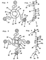
- the carrier element 12 that as an individual part 3 and 4 is shown - axially between the Electric motor 2 and the carrier part 6 or the housing wall 8 of the fan 10 arranged.
- the carrier element 12 has a motor holding section connected to the electric motor 2 24 and one connected to the carrier part 6 or on the essentially flat housing wall 8 supported carrier holding section 26.
- the two holding sections 24, 26 are in the first Execution of the invention on four elastic, web-like Connectors 28 connected together. Are there these connectors 28 designed so that the two Holding sections 24, 26 - and thus also the Electric motor 2 and the carrier part 6 - three-dimensional, i.e. in all spatial directions, namely axially, radially and tangentially, each over a certain range of motion are elastically movable relative to each other.
- the Connectors 28 cause the actual vibration engineering Decoupling of electric motor 2 and blower 10, especially in the tangential direction.
- the four connecting pieces 28 are uniform over the circumference distributed and thus each 90 ° in Spaced circumferentially to each other.
- the two holding sections 24, 26 and the connecting pieces 28 are according to the invention in one piece, preferably as a bent stamped part made of metal, in particular spring steel sheet, educated.
- the carrier element 12 is axial arranged between the carrier part 6 and the electric motor 2.
- the carrier holding section 26 is on its from the electric motor 2 axially opposite side with the carrier part 6 connected, in particular flat on the housing wall 8 attached.
- the carrier holding section 26 is in FIG the first embodiment of the invention from four peripherally the radially outward ends of the connectors 28 arranged, in particular circular, disks, which due to their arrangement relative to the motor holding section 24 and due to their shape in the following as Planetary disks 30 are called.
- the beam holding section 26 has an outer wall 32, which on a Mounting surface 34 of the carrier part 6 or its housing wall 8 is attachable.
- spring-elastic clamping parts 36 are provided for attachment to the support part 6 are according to the invention on the carrier holding section 26.
- each designed as clip glasses are, i.e. rosette-like, evenly over the circumference a central, in particular circular, opening 38 have distributed resilient retaining tongues 40.
- the Fan-side fastening of the clamping parts 36 takes place on attached to the front of the blower housing 8 cone-shaped Surveys 42.
- the motor holding section 24 is central, in particular circular disk-shaped, an inner one centrally on the electric motor 2 attachable wall 44 forming base plate 46 formed, of which the connecting pieces 28 are radial extend outward to the carrier holding portion 26.
- the Motor holding section 24 is on its from the support member 6 axially facing side connected to the electric motor 2, in particular also by means of a resilient Clamping part 48, which is also constructed in essence can be like the clamping parts 36 of the carrier holding section 26 and preferably at a central through opening 50 of the carrier element 12 for the motor shaft 20th or whose bearing support tube 18 is arranged.
- This too Clamping part 48 is a preferred embodiment a mounting eye that works as clip-on glasses with tabs 52 is formed.
- the clamp is attached to one Dome 54 (extension of the bearing support tube 18 of the stator 14) at the stator end of the motor 2.
- the walls 32 and 44 of the two holding sections 24, 26 are axially offset according to FIG. 1 with a certain distance, so that the carrier element 12 practically as a double disc is formed, the holding sections 24, 26 in two spaced apart, perpendicular to the motor axis aligned parallel planes on both sides of the elastic Connectors 28 are.
- the connectors 28 lie axially in between the walls 32, 44 of the two Holding sections 24, 26 formed space.
- Each connector 28 consists of an elastic Strip material that regarding its about the Stripe width transverse axis parallel to the motor axis (Motor shaft 20) is aligned.
- each connecting piece 28 by an approximately S or. meandering course with several approximately radial and tangentially aligned, via bends 52a, 52b, 52c, 52d, 52e, 52f, 52g connected sections 54a, 54b, 54c, 54d, 54e, 54f, 54g, 54h.
- a first goes approximately tangentially Motor holding section 24 aligned, radially inner Section 54a into an approximately 90 ° bend 52a second, approximately radially directed section 54b and then via a further approximately 90 ° bend 52b into a third approximately tangential section 54c.
- a fourth, approximately radial Section 54d which in turn has a fourth, approximately 90 ° bend 52d into a fifth approximately tangential Section 54e merges.
- This fifth section 54e goes then a fifth, approximately 180 ° bend 52e into one another (sixth) section arranged approximately tangentially 54f above, which is approximately tangent to the extension of the first directed section 54a. Between the first Section 54a and sixth section 54f is therefore a Loop.
- the sixth section 54f adjoins a further 90 ° bend 52f a seventh, approximately radial extending portion 54g that directly onto the carrier holding portion 26 approaches. This finally passes over a final bend 52g into a radially outer one, about tangential section 54g such that the both to be attached to the holding sections 24, 26 End regions (first section 54a, last section 54g) are substantially radially opposite one another.
- the one-piece support element according to the invention 12 is immediately ready for installation. It can be simple at first Be connected to the electric motor 2, the Spring-elastic clamping part of the motor holding section 24 the dome 51 of the electric motor 2 is pushed in the axial direction and there, especially with the spread of rosette-like spring tongues 40 is jammed. The cathedral 51 of the electric motor 2 is then - in particular on the Spring tongues of the clamping goggles - against axial backward displacement kept secure. The clamping part cannot be Pull off more because it clings to the electric motor 2. Then the housing wall facing the motor 2 8 of the blower 10 in the same manner with the carrier holding section 26 connected. The attachment can be simple be made from the outside of the blower 10.
- FIGS. 6 and 7 differs from the first embodiment in that not only four but only three connecting pieces 28 and planet disks 30 in the carrier holding section 26 are provided, which are uniform over the circumference distributed and thus 120 ° in the circumferential direction are spaced from each other. Through this execution the assembly effort for the connection is reduced of the blower 10 with the support element 12. Otherwise has the second version has the same structure as the first Execution on.
- the preferred application example illustrated in Figs. 8 and 9 differs from the first embodiment in that the motor holding portion 24 for connection with the electric motor 2 not only a resilient Clamping part 48, but four such clamping parts 48a has that evenly distributed on the circumference of a Circle are arranged, the concentric to the centric Feed-through opening 49 of the carrier element 12 for the motor shaft 20 runs.
- This design increases the Security of the connection of the electric motor 2 with the Support element 12.
- On the electric motor 2 are for this version to provide four fastening pins (not shown), into which the base plate 46 engages by clamping.
- the third embodiment also has the same Structure like the first version.
- the invention provides effective vibration isolation achieved in all directions. This happens on the one hand through the characteristic formation of the Connectors 28, on the other hand, also act Clamping parts 36, 48, 48a with that within certain narrow limits allow an (anti-vibration) axial movement. Overall, the invention advantageously a self-limiting vibration movement of the support element 12 reached without special stop parts would be necessary.
- the invention is not based on the illustrated embodiments limited, but also includes all in the sense of Invention equivalent effects. So was on the possible application of the invention for internal rotor motors already referenced. It has also been pointed out that the attachment of the motor holding section 26 to the electric motor 2 can also be done by a screw.
- the shown version has a Screwing the advantage that the functioning as a vibrating part Carrier element 12 not only together with the electric motor 2 relative movements in relation to the carrier part 6, but also relative movements relative to the electric motor itself 2 can perform, which is advantageous its vibration isolation efficiency increases. Besides, is the connection described less technically elaborate, no lost parts are used have to.
Landscapes
- Engineering & Computer Science (AREA)
- Mechanical Engineering (AREA)
- General Engineering & Computer Science (AREA)
- Power Engineering (AREA)
- Structures Of Non-Positive Displacement Pumps (AREA)
- Motor Or Generator Frames (AREA)
- Connection Of Motors, Electrical Generators, Mechanical Devices, And The Like (AREA)
Description
- Fig. 1
- einen Axialschnitt durch einen Elektromotor und ein Gebläse als Trägerteil, wobei zur schwingungsisolierenden Halterung eine erste Ausführung der Erfindung in der dargestellten Anordnung vorgesehen ist,
- Fig. 2
- eine Aufsicht auf das Gebläse gemäß der in Fig. 1 gezeigten Ausführung in der Ebene II-II,
- Fig. 3
- eine Aufsicht auf die erste Ausführung der Erfindung in einer der Fig. 2 entsprechenden Darstellung, jedoch ohne das Gebläse,
- Fig. 4
- eine Schnittdarstellung der ersten Ausführung der Erfindung in einer Fig. 1 entsprechenden Darstellung, jedoch weder mit Elektromotor noch mit Gebläse,
- Fig. 5
- eine vergrößerte Darstellung eines Verbindungsstücks aus Fig. 3,
- Fig. 6
- eine Aufsicht auf eine zweite Ausführung einer erfindungsgemäßen Anordnung in einer Fig. 3 entsprechenden Darstellung,
- Fig. 7
- eine Schnittdarstellung einer zweiten Ausführung der Erfindung in einer Fig. 4 entsprechenden Darstellung,
- Fig. 8
- eine Aufsicht auf eine dritte Ausführung der Erfindung in einer Fig. 3 entsprechenden Darstellung,
- Fig. 9
- eine Schnittdarstellung der dritten Ausführung der erfindungsgemäßen Anordnung in einer Fig. 4 entsprechenden Darstellung.
- 2
- Elektromotor
- 4
- Gebläserad
- 6
- Trägerteil
- 8
- Gehäusewandung
- 10
- Gebläse
- 12
- Trägerelement
- 14
- Stator von 2
- 16
- Außenläufer von 2
- 18
- Lagertragrohr von 2
- 20
- Motorwelle von 2
- 22
- Öffnung in 8 für 20
- 24
- Motor-Halteabschnitt von 12
- 26
- Träger-Halteabschnitt von 12
- 28
- Verbindungsstück für 24 und 26
- 30
- Planetenscheibe von 26
- 32
- Wandung von 26
- 34
- Montagefläche an 6
- 36
- Klemmteil an 26
- 38
- Öffnung von 36
- 40
- Haltezunge von 36
- 42
- zapfenförmige Erhebung auf 6
- 44
- Wandung von 24
- 46
- Basisscheibe von 24
- 48, 48a
- Klemmteil an 24
- 49
- Durchführungsöffnung in 12 für 20 bzw. 18
- 50
- Haltezunge von 48
- 51
- Dom an 2
- 52a bis g
- Biegungen von 28
- 54a bis h
- Abschnitte von 28
- 56
- Leiterplatte
Claims (12)
- Trägerelement (12) zur schwingungsisolierenden Halterung eines Elektromotors (2) an einem Trägerteil (6), welches Trägerelement (12) einen Motor-Halteabschnitt (24) zum Verbinden mit dem Elektromotor (2) und einen Träger-Halteabschnitt (26) zum Verbinden mit dem Trägerteil (6) aufweist, wobei die beiden Halteabschnitte (24, 26) über elastische, stegartige Verbindungsstücke (28) verbunden sind, die derart ausgelegt sind, daß die beiden Halteabschnitte (24, 26) dreidimensional, in allen Raumrichtungen, und zwar axial, radial und tangential, über einen bestimmten Bewegungsspielraum hinweg relativ zueinander elastisch beweglich sind, wobei die beiden Halteabschnitte (24, 26) und die Verbindungsstücke (28) miteinander einstückig ausgebildet sind,
dadurch gekennzeichnet, daß der Träger-Halteabschnitt (26) zur Befestigung am Trägerteil (6) federelastische Klemmteile (36) aufweist. - Trägerelement (12) nach Anspruch 1,
dadurch gekennzeichnet, daß der Träger-Halteabschnitt (26) zur Befestigung am Trägerteil (6) drei oder vier federelastische Klemmteile (36) aufweist. - Trägerelement (12) nach Anspruch 1 oder 2,
dadurch gekennzeichnet, daß der Motor-Halteabschnitt (24) als zentrale, insbesondere kreisförmige, Basisscheibe (46) ausgebildet ist, von der sich die Verbindungsstücke (28) radial nach außen erstrecken. - Trägerelement (12) nach einem der Ansprüche 1 bis 3,
dadurch gekennzeichnet, daß der Motor-Halteabschnitt (24) zum Verbinden mit dem Elektromotor (2) mindestens ein federelastisches Klemmteil (48) aufweist, das vorzugsweise an einer zentrischen Durchführöffnung (49) des Trägerelementes (12) für eine Motorwelle (20) angeordnet ist. - Trägerelement (12) nach einem der Ansprüche 1 bis 4,
dadurch gekennzeichnet, daß der Motor-Halteabschnitt (24) zum Verbinden mit dem Elektromotor (2) mehrere, insbesondere vier, federelastische Klemmteile (48a) aufweist, die vorzugsweise konzentrisch um eine zentrische Durchführöffnung (49) des Trägerelementes (12) für eine Motorwelle (20) angeordnet sind. - Trägerelement (12) nach einem der Ansprüche 1 bis 5,
dadurch gekennzeichnet, daß die federelastischen Klemmteile (36, 48, 48a) als Klemmbrille ausgebildet sind. - Trägerelement (12) nach einem der Ansprüche 1 bis 6,
dadurch gekennzeichnet, daß die Halteabschnitte (24, 26) und die Verbindungsstücke (28) als ein Biege-Stanzteil aus Metall, insbesondere aus Federstahlblech, ausgebildet sind. - Trägerelement (12) nach einem der Ansprüche 1 bis 7,
dadurch gekennzeichnet, daß die Halteabschnitte (24, 26) in zwei zueinander beabstandeten, senkrecht zur Motorachse ausgerichteten Parallelebenen liegen. - Trägerelement (12) nach einem der Ansprüche 1 bis 8 ,
dadurch gekennzeichnet, daß jedes Verbindungsstück (28) aus einem elastischen Streifenmaterial besteht, das bezüglich seiner über die Streifenbreite verlaufenden Querachse parallel zur Motorachse (20) ausgerichtet ist. - Trägerelement (12) nach einem der Ansprüche 1 bis 9,
dadurch gekennzeichnet, daß jedes Verbindungsstück (28) zwischen seinen radial äußeren und inneren, insbesondere jeweils in radialer Richtung etwa auf dem gleichen Radius gegenüberliegenden Endbereichen einen verlängerten, die elastische Beweglichkeit erhöhenden Verlauf aufweist, wozu vorzugsweise jedes Verbindungsstück (28) zwischen seinen Endbereichen einen etwa S-förmigen oder mäanderförmigen Verlauf mit mehreren über Biegungen (52a, 52b, 52c, 52d, 52e, 52f, 52g) verbundenen Abschnitten (54a, 54b, 54c, 54d, 54e, 54f, 54g, 54h) aufweist. - Anordnung zur schwingungsisolierenden Halterung eines Elektromotors (2) an einem Trägerteil (6), mit einem Elektromotor (2) und mit einem Trägerteil (6) sowie mit einem Trägerelement (12),
dadurch gekennzeichnet, daß das Trägerelement (1) nach einem der Ansprüche 1 bis 10 ausgebildet und axial zwischen dem Elektromotor (2) und dem Trägerelement (12) eine Leiterplatte (56) angeordnet ist. - Anordnung nach Anspruch 11,
dadurch gekennzeichnet, daß das Trägerteil (6) ein Gebläse (10) ist.
Applications Claiming Priority (2)
| Application Number | Priority Date | Filing Date | Title |
|---|---|---|---|
| DE19936178 | 1999-07-31 | ||
| DE19936178A DE19936178A1 (de) | 1999-07-31 | 1999-07-31 | Anordnung zur schwingungsisolierenden Halterung eines Elektromotors |
Publications (3)
| Publication Number | Publication Date |
|---|---|
| EP1075075A2 EP1075075A2 (de) | 2001-02-07 |
| EP1075075A3 EP1075075A3 (de) | 2002-02-06 |
| EP1075075B1 true EP1075075B1 (de) | 2004-11-03 |
Family
ID=7916810
Family Applications (1)
| Application Number | Title | Priority Date | Filing Date |
|---|---|---|---|
| EP00112474A Expired - Lifetime EP1075075B1 (de) | 1999-07-31 | 2000-06-10 | Anordnung zur schwingungsisolierenden Halterung eines Elektromotors |
Country Status (2)
| Country | Link |
|---|---|
| EP (1) | EP1075075B1 (de) |
| DE (2) | DE19936178A1 (de) |
Cited By (1)
| Publication number | Priority date | Publication date | Assignee | Title |
|---|---|---|---|---|
| EP4080061A1 (de) | 2021-04-22 | 2022-10-26 | Pittway Sarl | Dämpfungsvorrichtung für einen elektromotor für einen ventilator |
Families Citing this family (2)
| Publication number | Priority date | Publication date | Assignee | Title |
|---|---|---|---|---|
| EP2466147A1 (de) * | 2010-12-14 | 2012-06-20 | Elica S.p.A. | Radialventilator und Elektromotor, durch einen Schwingungsdämpfer miteinander verbunden |
| EP3745564B1 (de) * | 2019-05-31 | 2026-05-06 | Soler & Palau Research, S.L. | Dämpfungsmittel eines elektromotors einer luftstromerzeugungsvorrichtung und vorrichtung mit dem dämpfungsmittel |
Family Cites Families (2)
| Publication number | Priority date | Publication date | Assignee | Title |
|---|---|---|---|---|
| US3506226A (en) * | 1968-06-25 | 1970-04-14 | Minnesota Mining & Mfg | Vibration isolating motor bracket |
| US4452417A (en) * | 1981-09-14 | 1984-06-05 | Honeywell Inc. | Vibration isolating motor mount |
-
1999
- 1999-07-31 DE DE19936178A patent/DE19936178A1/de not_active Withdrawn
-
2000
- 2000-06-10 DE DE50008480T patent/DE50008480D1/de not_active Expired - Fee Related
- 2000-06-10 EP EP00112474A patent/EP1075075B1/de not_active Expired - Lifetime
Cited By (2)
| Publication number | Priority date | Publication date | Assignee | Title |
|---|---|---|---|---|
| EP4080061A1 (de) | 2021-04-22 | 2022-10-26 | Pittway Sarl | Dämpfungsvorrichtung für einen elektromotor für einen ventilator |
| WO2022223826A1 (en) | 2021-04-22 | 2022-10-27 | Pittway Sarl | Damping device for an electric motor for a ventilator |
Also Published As
| Publication number | Publication date |
|---|---|
| EP1075075A2 (de) | 2001-02-07 |
| EP1075075A3 (de) | 2002-02-06 |
| DE50008480D1 (de) | 2004-12-09 |
| DE19936178A1 (de) | 2001-02-01 |
Similar Documents
| Publication | Publication Date | Title |
|---|---|---|
| DE69006643T2 (de) | Scharniervorrichtung zur Drehkupplung zweier Elemente. | |
| DE2515234C3 (de) | Halter zum schwingungsdämpfenden Befestigen eines Mikrophons im Inneren eines elektrischen Gerätes | |
| EP0871278B1 (de) | Anordnung zur schwingungsisolierenden Aufhängung eines Elektromotors | |
| DE102014201742A1 (de) | Stellantrieb für ein kraftfahrzeug, insbesondere für einen kraftfahrzeugsitz | |
| WO2004112219A1 (de) | Entkopplungsvorrichtung für elektromotoren und verfahren zur herstellung eines elektromotors | |
| EP0349937B1 (de) | Elektrisches Installationsgerät | |
| DE29900923U1 (de) | Anordnung zur schwingungsisolierenden Halterung eines Elektromotors | |
| DE102016204784A1 (de) | Wellgetriebe | |
| DE3103782A1 (de) | "elektromotor" | |
| EP2115822A2 (de) | Winkelsteckverbinder mit veränderbarer abgangsrichtung | |
| EP2693170B1 (de) | Statorkupplung | |
| DE19833982B4 (de) | Pendelgleitlager | |
| DE202013012278U1 (de) | Winkelsteckverbinder mit einstellbarer Abgangsrichtung | |
| DE19918521B4 (de) | Anordnung zur Befestigung von Permanentmagnetsegmenten | |
| EP0926803B1 (de) | Anordnung zur schwingungsisolierenden Halterung eines Elektromotors | |
| DE19542072C2 (de) | Kupplungsfederelement | |
| EP1075075A2 (de) | Anordnung zur schwingungsisolierenden Halterung eines Elektromotors | |
| DE69609437T2 (de) | Drehpositionsdetektor für Drehantrieb | |
| DE102015213021A1 (de) | Elektromotor | |
| DE102021205499A1 (de) | Antriebsvorrichtung und Statorbaugruppe hierfür | |
| DE10102516A1 (de) | Elektrischer Stellantrieb, insbesondere für Heizungs- Lüftungs- oder Klimaklappen in einem Kraftfahrzeug | |
| DE102020105709A1 (de) | Linearsystem und Verfahren zur Montage solch eines Linearsystems | |
| EP0926388B1 (de) | Torsionsschwingungsdämpfer | |
| EP0713283B1 (de) | Vorrichtung zur Halterung eines Elektromotors | |
| DE4031167C2 (de) | Elektrische Leuchte |
Legal Events
| Date | Code | Title | Description |
|---|---|---|---|
| PUAI | Public reference made under article 153(3) epc to a published international application that has entered the european phase |
Free format text: ORIGINAL CODE: 0009012 |
|
| AK | Designated contracting states |
Kind code of ref document: A2 Designated state(s): AT BE CH CY DE DK ES FI FR GB GR IE IT LI LU MC NL PT SE Kind code of ref document: A2 Designated state(s): DE FR GB IT NL |
|
| AX | Request for extension of the european patent |
Free format text: AL;LT;LV;MK;RO;SI |
|
| PUAL | Search report despatched |
Free format text: ORIGINAL CODE: 0009013 |
|
| AK | Designated contracting states |
Kind code of ref document: A3 Designated state(s): AT BE CH CY DE DK ES FI FR GB GR IE IT LI LU MC NL PT SE |
|
| AX | Request for extension of the european patent |
Free format text: AL;LT;LV;MK;RO;SI |
|
| 17P | Request for examination filed |
Effective date: 20020323 |
|
| AKX | Designation fees paid |
Free format text: DE FR GB IT NL |
|
| 17Q | First examination report despatched |
Effective date: 20031201 |
|
| RAP1 | Party data changed (applicant data changed or rights of an application transferred) |
Owner name: EBM-PAPST MULFINGEN GMBH & CO.KG |
|
| GRAP | Despatch of communication of intention to grant a patent |
Free format text: ORIGINAL CODE: EPIDOSNIGR1 |
|
| GRAS | Grant fee paid |
Free format text: ORIGINAL CODE: EPIDOSNIGR3 |
|
| GRAA | (expected) grant |
Free format text: ORIGINAL CODE: 0009210 |
|
| AK | Designated contracting states |
Kind code of ref document: B1 Designated state(s): DE FR GB IT NL |
|
| REG | Reference to a national code |
Ref country code: GB Ref legal event code: FG4D Free format text: NOT ENGLISH |
|
| GBT | Gb: translation of ep patent filed (gb section 77(6)(a)/1977) | ||
| REF | Corresponds to: |
Ref document number: 50008480 Country of ref document: DE Date of ref document: 20041209 Kind code of ref document: P |
|
| REG | Reference to a national code |
Ref country code: IE Ref legal event code: FG4D Free format text: GERMAN |
|
| REG | Reference to a national code |
Ref country code: IE Ref legal event code: FD4D |
|
| ET | Fr: translation filed | ||
| PLBE | No opposition filed within time limit |
Free format text: ORIGINAL CODE: 0009261 |
|
| STAA | Information on the status of an ep patent application or granted ep patent |
Free format text: STATUS: NO OPPOSITION FILED WITHIN TIME LIMIT |
|
| 26N | No opposition filed |
Effective date: 20050804 |
|
| PGFP | Annual fee paid to national office [announced via postgrant information from national office to epo] |
Ref country code: NL Payment date: 20090630 Year of fee payment: 10 |
|
| PGFP | Annual fee paid to national office [announced via postgrant information from national office to epo] |
Ref country code: IT Payment date: 20090612 Year of fee payment: 10 Ref country code: FR Payment date: 20090527 Year of fee payment: 10 |
|
| PGFP | Annual fee paid to national office [announced via postgrant information from national office to epo] |
Ref country code: GB Payment date: 20090610 Year of fee payment: 10 Ref country code: DE Payment date: 20090821 Year of fee payment: 10 |
|
| REG | Reference to a national code |
Ref country code: NL Ref legal event code: V1 Effective date: 20110101 |
|
| GBPC | Gb: european patent ceased through non-payment of renewal fee |
Effective date: 20100610 |
|
| REG | Reference to a national code |
Ref country code: FR Ref legal event code: ST Effective date: 20110228 |
|
| PG25 | Lapsed in a contracting state [announced via postgrant information from national office to epo] |
Ref country code: IT Free format text: LAPSE BECAUSE OF NON-PAYMENT OF DUE FEES Effective date: 20100610 |
|
| PG25 | Lapsed in a contracting state [announced via postgrant information from national office to epo] |
Ref country code: DE Free format text: LAPSE BECAUSE OF NON-PAYMENT OF DUE FEES Effective date: 20110101 |
|
| PG25 | Lapsed in a contracting state [announced via postgrant information from national office to epo] |
Ref country code: NL Free format text: LAPSE BECAUSE OF NON-PAYMENT OF DUE FEES Effective date: 20110101 Ref country code: FR Free format text: LAPSE BECAUSE OF NON-PAYMENT OF DUE FEES Effective date: 20100630 |
|
| PG25 | Lapsed in a contracting state [announced via postgrant information from national office to epo] |
Ref country code: GB Free format text: LAPSE BECAUSE OF NON-PAYMENT OF DUE FEES Effective date: 20100610 |