EP1075054A1 - Shorting contact support for a plug-in projection in an igniter receptacle - Google Patents
Shorting contact support for a plug-in projection in an igniter receptacle Download PDFInfo
- Publication number
- EP1075054A1 EP1075054A1 EP00114938A EP00114938A EP1075054A1 EP 1075054 A1 EP1075054 A1 EP 1075054A1 EP 00114938 A EP00114938 A EP 00114938A EP 00114938 A EP00114938 A EP 00114938A EP 1075054 A1 EP1075054 A1 EP 1075054A1
- Authority
- EP
- European Patent Office
- Prior art keywords
- shorting
- plug
- contact
- contact support
- bridge
- Prior art date
- Legal status (The legal status is an assumption and is not a legal conclusion. Google has not performed a legal analysis and makes no representation as to the accuracy of the status listed.)
- Granted
Links
- 238000003780 insertion Methods 0.000 claims abstract description 12
- 230000037431 insertion Effects 0.000 claims abstract description 12
- 239000002184 metal Substances 0.000 claims abstract description 11
- 230000000452 restraining effect Effects 0.000 claims 1
- 230000000295 complement effect Effects 0.000 description 2
- 230000001419 dependent effect Effects 0.000 description 1
- 210000002105 tongue Anatomy 0.000 description 1
Images


Classifications
-
- F—MECHANICAL ENGINEERING; LIGHTING; HEATING; WEAPONS; BLASTING
- F02—COMBUSTION ENGINES; HOT-GAS OR COMBUSTION-PRODUCT ENGINE PLANTS
- F02P—IGNITION, OTHER THAN COMPRESSION IGNITION, FOR INTERNAL-COMBUSTION ENGINES; TESTING OF IGNITION TIMING IN COMPRESSION-IGNITION ENGINES
- F02P13/00—Sparking plugs structurally combined with other parts of internal-combustion engines
-
- H—ELECTRICITY
- H01—ELECTRIC ELEMENTS
- H01R—ELECTRICALLY-CONDUCTIVE CONNECTIONS; STRUCTURAL ASSOCIATIONS OF A PLURALITY OF MUTUALLY-INSULATED ELECTRICAL CONNECTING ELEMENTS; COUPLING DEVICES; CURRENT COLLECTORS
- H01R13/00—Details of coupling devices of the kinds covered by groups H01R12/70 or H01R24/00 - H01R33/00
- H01R13/66—Structural association with built-in electrical component
- H01R13/70—Structural association with built-in electrical component with built-in switch
- H01R13/703—Structural association with built-in electrical component with built-in switch operated by engagement or disengagement of coupling parts, e.g. dual-continuity coupling part
- H01R13/7031—Shorting, shunting or bussing of different terminals interrupted or effected on engagement of coupling part, e.g. for ESD protection, line continuity
- H01R13/7032—Shorting, shunting or bussing of different terminals interrupted or effected on engagement of coupling part, e.g. for ESD protection, line continuity making use of a separate bridging element directly cooperating with the terminals
-
- H—ELECTRICITY
- H01—ELECTRIC ELEMENTS
- H01R—ELECTRICALLY-CONDUCTIVE CONNECTIONS; STRUCTURAL ASSOCIATIONS OF A PLURALITY OF MUTUALLY-INSULATED ELECTRICAL CONNECTING ELEMENTS; COUPLING DEVICES; CURRENT COLLECTORS
- H01R2201/00—Connectors or connections adapted for particular applications
- H01R2201/26—Connectors or connections adapted for particular applications for vehicles
Definitions
- the invention relates to a shorting contact support for a plug-in projection in an igniter receptacle according to the preamble to Patent Claim 1.
- Such shorting contact supports are used, in particular, in airbag ignition systems in order to short the contact pins on the igniter receptacle so that the ignition cartridge is in no way able to reach an undefined potential, with the result that unintentional ignition of the ignition cartridge is effectively prevented.
- the document DE 197 28 448 has disclosed a plug connector for connection to an igniter receptacle, having a plug-in projection, locking arms and a plug body secured by a bar-like secondary locking mechanism with tongues running parallel to locking arms. Furthermore, this secondary locking mechanism has a spike which opens the shorting bridge between the contact pins of the igniter when the plug is secured in the contact support.
- the plug-in projection on the plug and the complementary holder in the contact support are of asymmetrical design, so that they can both be inserted with only one orientation. The shorting contact support can likewise be inserted into the igniter receptacle with one orientation.
- FIG. 7 shows a plan view of a motor vehicle 1 having three modules 72, 73 and 74 mounted close to the door.
- a module should be understood in this case to mean a gas generator having, by way of example, an ignition receptacle, an igniter and a primer 79 for an airbag.
- the manufacturer requires the outgoing cables from the plug 75 to be always directed towards the rear, for example, or else the primer 79 should always point into the interior of the car.
- this module needs to be rotated through 180° so that the mounting plate 78 always points outwards, for example, and the primer 79 always points inwards.
- the ignition receptacle of the module is naturally also rotated through 180° as well, although the antireversal shorting contact support means that the plug 76 can then be inserted only in such a way that the outgoing cable points towards the front, as can be seen with regard to module 73.
- a particular disadvantage of such shorting contact supports is that, when installing the side airbag, the manufacturer requires two different modules with ignition receptacles rotated through 180° for the two sides of the motor vehicle, or else two different shorting contact supports, one for the left-hand side and one for the right-hand side, so that the outgoing cable for the plug 77 also points in the same direction for the other (left-hand) side of the motor vehicle, as shown for module 74, for example.
- the object of the invention is to eliminate the aforementioned disadvantages without increasing the number of components required for an airbag ignition system.
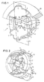
- FIG. 1 An oblique plan view of an inventive shorting contact support can be seen in Figure 1 from the front and in Figure 2 from the back.
- the shorting contact support 1 has a non-conductive support housing 9 having an annular base 2 on which two diametrically opposite wings 3 and 4 are integrally formed parallel to the insertion direction and form a holder 5 for a plug 6.
- the support housing 9 is bounded by a cylindrical circumferential surface, and, from this circumferential surface, a respective lobe 7 and 8 for coding purposes is integrally formed outwards on the front of the wings at right angles to the insertion direction.
- the essentially semicircular lobes 7 and 8 are arranged such that they are not diametrically opposite.
- cylindrical circumferential surface has protruding latching lugs 11 and 12 which are able to latch into corresponding cutouts made in the igniter receptacle 20.
- guide lugs 13 and 14 running in the insertion direction are integrally formed on the cylindrical circumferential surface.
- the essentially rectangular holder 5 is framed by the surfaces 15 and 17 (running parallel to the insertion direction) of the wings 3 and 4, with guide shoulders 18 and 19 which project into the holder 5 and run parallel to the insertion direction being integrally formed on these surfaces 15 and 17. These guide shoulders must be situated exactly in the centre of the surfaces 15 and 17 so that the holder 5 is rotationally symmetrical through 180°.
- the igniter receptacle 20 shown in Figure 1 has two contact pins 21 and 22 which run in the plug-in direction, lie in one plane and project from the bottom of the cylindrical opening 24 for holding the shorting contact support 1.
- This opening 24 made in the igniter receptacle 20 has complementary cutouts on its front for the lobes 7 and 8.
- Figure 3 shows a perspective illustration of a shorting bridge 30 having an essentially rectangular metal plate 31 with an essentially rectangular window 32 cut out of it, in which a finger 33 which is directed outwards in the insertion direction and has a shoulder 34 is integrally formed in the top edge of the window.
- two inwardly directed contact elements 35 and 36 are integrally formed on the top edge 37 of the metal plate 31.
- Each contact element 35, 36 comprises a starting region 41 integrally formed on the front edge 37 of the metal plate 31 and at right angles thereto, a central region 42 extending the starting region at right angles thereto and parallel to the metal plate 31, and an end region 43 running essentially at right angles to the metal plate 31, the central region 42 being connected to the end region 43 by means of a corner 44 pointing away from the plate 31.
- Figure 4 shows a section along the plane G of the shorting contact support 1 situated in the igniter receptacle 20.
- the sectional plane runs at right angles to the metal plate 31 of the shorting bridge 30, so that this shorting bridge 30 can be seen only from the side in this figure.
- the shorting contact support 1 additionally contains a shorting bridge 30a and 30b in each wing 3 and 4, said shorting bridges being arranged such that the two metal plates 31a and 31b are arranged parallel to and in the wings 3 and 4.
- the contact elements 35 and 36 project into the holder 5, the central regions 42 of these contact elements 35, 36 being directed downwards onto the plane which passes through the base 2, so that the end region 43 runs parallel to this plane.
- the two shorting bridges are arranged with mirror-image symmetry with respect to the plane which passes through the contact pins 21 and 22.
- a contact pin 22 is touched by a respective contact element of one shorting bridge 30a and by the other shorting bridge 30b.
- Figures 1 and 2 also clearly show that the contact pins 21 and 22 are each touched by two contact elements, the top contact element belonging to the top shorting bridge 30a and the bottom contact element belonging to the bottom shorting bridge 30b. This ensures that the two contact pins 21 and 22 are shorted both by one shorting bridge 30a and by the other shorting bridge 30b.
- Figure 5 shows a partially cut-away plug-in projection on the plug 6.
- the essentially rectangular plug-in projection 50 extending in the plug-in direction, has two sockets 51 and 52 for holding the contact pins 21 and 22.
- Two grooves 55 and 56 for accommodating the guide shoulders 18 and 19 are made in the lateral length surfaces of the plug-in projection 50, in the plug-in direction. These grooves are situated exactly in the centre of the lateral length surfaces of the plug-in projection 50 so that said plug-in projection can be inserted into the holder when rotated through 180°.
- a respective shoulder 53 and 54 is integrally formed, running in the plug-in direction, on one side of the length surfaces at the height of the sockets, so that the left-hand half of the plug-in projection is mirror-image symmetrical with respect to the right-hand half of the plug-in projection, the mirror plane passing through the two grooves 55 and 56.
- a latching arm 57 with a latching lug 58 for latching into the igniter receptacle 20 is integrally formed on each width side of the plug-in projection 50.
- a shorting contact support 1 is first inserted into the ignition receptacle 20, with one shorting bridge 30a and the other shorting bridge 30b shorting the two contact pins 21 and 22 on the igniter receptacle 20.
- the plug-in projection 50 on the plug shown in Figure 6 is inserted into the holder 5, and one shorting bridge, for example 30a, is lifted from the contact pins 21 and 22 by the shoulders 53 and 54 on the plug-in projection 50, so that the two contact pins are now shorted only by a single shorting bridge 30b.
- Figure 6 shows an oblique plan view of the plug 6 with the plug-in projection 50, the two shorting bridges 30a and 30b of the shorting contact support 1 being shown individually.
- the lower-case letters "a” and "b” have been introduced to distinguish the two shorting bridges and their associated elements.
- the shorting bridge 30a is situated in the wing 3 and the shorting bridge 30b is situated in the wing 4.
- the guide shoulders 18 and 19 enter the grooves 55 and 56.
- the shoulders 53 and 54 approach the two corners 44a of the two contact elements 35a and 36a of the shorting bridge 30a (see Figure 5).
- the contact elements 35a and 36a are accordingly removed from the contact pins 21 and 22. Since there are no such shoulders 53, 54 on the other length side of the plug-in projection 50, the contact elements 35b and 36b remain touching the contact pins 21 and 22, so that the latter are still shorted. If, instead of this, the plug-in projection is inserted rotated through 180°, the shorting bridge 30b is removed instead of the contact bridge 30a. Only during secondary locking by means of a bar with a spike (not shown), for example, is one of the two contact elements 35b or 36b which is still in contact removed from a contact pin 21 or 22. In this case, this spike slides between the plug-in projection 50 and the contact element 35b or 36b which is to be raised, and the spike then descends below the corner 44b and raises the element accordingly.
- the plug connector is consequently locked and activated, i.e. the primer would be ready for use.
Landscapes
- Engineering & Computer Science (AREA)
- Chemical & Material Sciences (AREA)
- Combustion & Propulsion (AREA)
- Mechanical Engineering (AREA)
- General Engineering & Computer Science (AREA)
- Air Bags (AREA)
- Connector Housings Or Holding Contact Members (AREA)
Abstract
Description
- The invention relates to a shorting contact support for a plug-in projection in an igniter receptacle according to the preamble to Patent Claim 1.
- Such shorting contact supports are used, in particular, in airbag ignition systems in order to short the contact pins on the igniter receptacle so that the ignition cartridge is in no way able to reach an undefined potential, with the result that unintentional ignition of the ignition cartridge is effectively prevented. In this context, it is important for the shorting bridge between the contact pins to be opened when the plug is inserted or secondarily locked in the shorting contact support.
- The document DE 197 28 448 has disclosed a plug connector for connection to an igniter receptacle, having a plug-in projection, locking arms and a plug body secured by a bar-like secondary locking mechanism with tongues running parallel to locking arms. Furthermore, this secondary locking mechanism has a spike which opens the shorting bridge between the contact pins of the igniter when the plug is secured in the contact support. The plug-in projection on the plug and the complementary holder in the contact support are of asymmetrical design, so that they can both be inserted with only one orientation. The shorting contact support can likewise be inserted into the igniter receptacle with one orientation.
- By way of example, such shorting contact supports are used in side airbag ignition systems. Figure 7 shows a plan view of a motor vehicle 1 having three
modules 72, 73 and 74 mounted close to the door. A module should be understood in this case to mean a gas generator having, by way of example, an ignition receptacle, an igniter and a primer 79 for an airbag. When a first module 72 is installed on the right-hand side of the motor vehicle, the manufacturer requires the outgoing cables from the plug 75 to be always directed towards the rear, for example, or else the primer 79 should always point into the interior of the car. If the identical module is to be used for the left-hand side, this module needs to be rotated through 180° so that themounting plate 78 always points outwards, for example, and the primer 79 always points inwards. When the module 72 is rotated, the ignition receptacle of the module is naturally also rotated through 180° as well, although the antireversal shorting contact support means that theplug 76 can then be inserted only in such a way that the outgoing cable points towards the front, as can be seen with regard tomodule 73. Thus, a particular disadvantage of such shorting contact supports is that, when installing the side airbag, the manufacturer requires two different modules with ignition receptacles rotated through 180° for the two sides of the motor vehicle, or else two different shorting contact supports, one for the left-hand side and one for the right-hand side, so that the outgoing cable for the plug 77 also points in the same direction for the other (left-hand) side of the motor vehicle, as shown for module 74, for example. - The object of the invention is to eliminate the aforementioned disadvantages without increasing the number of components required for an airbag ignition system.
- This object is achieved in accordance with the claims. The dependent claims characterize preferred embodiments of the present invention.
- The invention is explained in more detail below with the aid of the description of an illustrative embodiment with reference to the drawing, in which:
- Figure 1
- shows the front of an inventive shorting contact support inserted into a cut-away igniter receptacle;
- Figure 2
- shows the back of the inventive shorting contact support shown in Figure 1;
- Figure 3
- shows an oblique side view of an inventive shorting bridge,
- Figure 4
- shows a section along the plane G through the inventive shorting contact support shown in Figure 1;
- Figure 5
- shows a perspective illustration of a partially cut-away plug-in projection;
- Figure 6
- shows a perspective view of a plug having two shorting bridges located on the plug-in projection; and
- Figure 7
- shows a plan view of a motor vehicle having side-mounted modules.
- An oblique plan view of an inventive shorting contact support can be seen in Figure 1 from the front and in Figure 2 from the back. The shorting contact support 1 has a non-conductive support housing 9 having an
annular base 2 on which two diametricallyopposite wings 3 and 4 are integrally formed parallel to the insertion direction and form aholder 5 for a plug 6. The support housing 9 is bounded by a cylindrical circumferential surface, and, from this circumferential surface, arespective lobe 7 and 8 for coding purposes is integrally formed outwards on the front of the wings at right angles to the insertion direction. For coding purposes, the essentiallysemicircular lobes 7 and 8 are arranged such that they are not diametrically opposite. Furthermore, the cylindrical circumferential surface has protrudinglatching lugs igniter receptacle 20. In addition,guide lugs rectangular holder 5 is framed by thesurfaces 15 and 17 (running parallel to the insertion direction) of thewings 3 and 4, withguide shoulders holder 5 and run parallel to the insertion direction being integrally formed on thesesurfaces 15 and 17. These guide shoulders must be situated exactly in the centre of thesurfaces 15 and 17 so that theholder 5 is rotationally symmetrical through 180°. - As can be seen in Figure 4, the
igniter receptacle 20 shown in Figure 1 has twocontact pins cylindrical opening 24 for holding the shorting contact support 1. This opening 24 made in theigniter receptacle 20 has complementary cutouts on its front for thelobes 7 and 8. - Figure 3 shows a perspective illustration of a
shorting bridge 30 having an essentiallyrectangular metal plate 31 with an essentiallyrectangular window 32 cut out of it, in which afinger 33 which is directed outwards in the insertion direction and has ashoulder 34 is integrally formed in the top edge of the window. In addition, two inwardly directedcontact elements top edge 37 of themetal plate 31. Eachcontact element front edge 37 of themetal plate 31 and at right angles thereto, acentral region 42 extending the starting region at right angles thereto and parallel to themetal plate 31, and anend region 43 running essentially at right angles to themetal plate 31, thecentral region 42 being connected to theend region 43 by means of acorner 44 pointing away from theplate 31. - Figure 4 shows a section along the plane G of the shorting contact support 1 situated in the
igniter receptacle 20. In this case, the sectional plane runs at right angles to themetal plate 31 of theshorting bridge 30, so that this shortingbridge 30 can be seen only from the side in this figure. The shorting contact support 1 additionally contains a shortingbridge wing 3 and 4, said shorting bridges being arranged such that the twometal plates wings 3 and 4. In this arrangement, thecontact elements holder 5, thecentral regions 42 of thesecontact elements base 2, so that theend region 43 runs parallel to this plane. The two shorting bridges are arranged with mirror-image symmetry with respect to the plane which passes through thecontact pins contact pin 22 is touched by a respective contact element of oneshorting bridge 30a and by the other shortingbridge 30b. Figures 1 and 2 also clearly show that thecontact pins top shorting bridge 30a and the bottom contact element belonging to thebottom shorting bridge 30b. This ensures that the twocontact pins bridge 30a and by the other shortingbridge 30b. - Figure 5 shows a partially cut-away plug-in projection on the plug 6. The essentially rectangular plug-in
projection 50, extending in the plug-in direction, has twosockets contact pins grooves guide shoulders projection 50, in the plug-in direction. These grooves are situated exactly in the centre of the lateral length surfaces of the plug-inprojection 50 so that said plug-in projection can be inserted into the holder when rotated through 180°. Arespective shoulder grooves latching arm 57 with alatching lug 58 for latching into theigniter receptacle 20 is integrally formed on each width side of the plug-inprojection 50. - A brief description of an example of use is given below.
- During assembly of a side airbag, a shorting contact support 1 is first inserted into the
ignition receptacle 20, with oneshorting bridge 30a and theother shorting bridge 30b shorting the twocontact pins igniter receptacle 20. Next, the plug-inprojection 50 on the plug shown in Figure 6 is inserted into theholder 5, and one shorting bridge, for example 30a, is lifted from thecontact pins shoulders projection 50, so that the two contact pins are now shorted only by a single shortingbridge 30b. - Figure 6 shows an oblique plan view of the plug 6 with the plug-in
projection 50, the two shortingbridges bridge 30a is situated in thewing 3 and the shortingbridge 30b is situated in the wing 4. When the plug-inprojection 50 is inserted into theholder 5, the guide shoulders 18 and 19 enter thegrooves shoulders corners 44a of the twocontact elements bridge 30a (see Figure 5). As thesecorners 44a are overcome, thecontact elements such shoulders projection 50, thecontact elements 35b and 36b remain touching the contact pins 21 and 22, so that the latter are still shorted. If, instead of this, the plug-in projection is inserted rotated through 180°, the shortingbridge 30b is removed instead of thecontact bridge 30a. Only during secondary locking by means of a bar with a spike (not shown), for example, is one of the twocontact elements 35b or 36b which is still in contact removed from acontact pin projection 50 and thecontact element 35b or 36b which is to be raised, and the spike then descends below the corner 44b and raises the element accordingly. - The plug connector is consequently locked and activated, i.e. the primer would be ready for use.
Claims (7)
- Shorting contact support for a plug-in projection (5c) in an igniter receptacle, comprisingcharacterized in thata first shorting bridge (30a) having two resilient contact elements (35a, 36a) connected to one another by means of an edge (37) of a metal plate (31), anda support housing (9) having an annular base (2) on which two diametrically opposite wings (3, 4) are integrally formed parallel to the insertion direction and form a holder (5) for a plug (6) having sockets (51, 52) for the insertion of contact pins (21, 22) on an igniter receptacle (20),the shorting contact support has a second shorting bridge (30b) which is essentially identical to the first (30a), each wing (3, 4) containing a shorting bridge (30a, 30b), so that at least one bridge (30a, 30b) shorts the two contact pins (21, 22) arranged in one plane on the igniter receptacle (20) when the plug (6) is inserted,and in that the holder (5) is rotationally symmetrical through 180°.
- Shorting contact support according to Claim 1, characterized in that the wings (3, 4) are enveloped by a cylinder shape, a respective lobe (7, 8) being integrally formed on the free ends of the wings (3, 4) on the outside.
- Shorting contact support according to at least one of the preceding claims, characterized in that the wings (3, 4) each have an inwardly directed guide shoulder (18, 19) running parallel to the insertion direction in the centre.
- Shorting contact support according to at least one of the preceding claims, characterized in that the contact elements (35, 36) run from the top edge (37) to the bottom edge (39) of the essentially rectangular metal plate (31) at a slight distance from the plate (31).
- Shorting contact support according to at least one of the preceding claims, characterized in that the central region (42) of the contact elements (35, 36) runs essentially parallel to the plate (31), in that the end region (43) of the contact elements (35, 36) runs essentially transversely with respect to the insertion direction, and in that the contact elements (35, 36) each have, between the central regions (42) and the end regions (43), a corner (44) directed away from the metal plate (31).
- Shorting contact support according to at least one of the preceding claims, characterized in that the bridges (30a, 30b) are arranged with mirror-image symmetry with respect to one another in the wings (3, 4).
- Shorting contact support according to at least one of the preceding claims, characterized by its use in a plug connector with an igniter in a restraining system in motor vehicles.
Applications Claiming Priority (2)
| Application Number | Priority Date | Filing Date | Title |
|---|---|---|---|
| DE19936848 | 1999-08-05 | ||
| DE19936848A DE19936848C1 (en) | 1999-08-05 | 1999-08-05 | Short-circuit contact carrier for automobile airbag detonation system has 2 identical short-circuit bridges for cooperation with contact pins of detonator socket in 2 alternate 180 degree positions |
Publications (2)
| Publication Number | Publication Date |
|---|---|
| EP1075054A1 true EP1075054A1 (en) | 2001-02-07 |
| EP1075054B1 EP1075054B1 (en) | 2006-09-27 |
Family
ID=7917245
Family Applications (1)
| Application Number | Title | Priority Date | Filing Date |
|---|---|---|---|
| EP00114938A Expired - Lifetime EP1075054B1 (en) | 1999-08-05 | 2000-07-18 | Shorting contact support for a plug-in projection in an igniter receptacle |
Country Status (7)
| Country | Link |
|---|---|
| US (1) | US6422897B1 (en) |
| EP (1) | EP1075054B1 (en) |
| KR (1) | KR100685154B1 (en) |
| AT (1) | ATE341114T1 (en) |
| BR (1) | BR0003530A (en) |
| DE (2) | DE19936848C1 (en) |
| ES (1) | ES2272222T3 (en) |
Cited By (1)
| Publication number | Priority date | Publication date | Assignee | Title |
|---|---|---|---|---|
| WO2004020933A1 (en) * | 2002-08-30 | 2004-03-11 | Special Devices, Inc. | Initiator having integral features for orienting and holding an insertable electrical shunt |
Families Citing this family (8)
| Publication number | Priority date | Publication date | Assignee | Title |
|---|---|---|---|---|
| US6835079B2 (en) * | 2002-05-23 | 2004-12-28 | Positronic Industries, Inc. | Electrical connector assembly with shorting member |
| US6663421B1 (en) * | 2002-12-11 | 2003-12-16 | Fci Americas Technology, Inc. | Igniter shorting contact |
| DE102005004920B3 (en) * | 2005-02-02 | 2006-08-17 | Amphenol-Tuchel Electronics Gmbh | Contact protection for connectors with a shorting bridge with integrated switching element |
| JP2008049941A (en) * | 2006-08-28 | 2008-03-06 | Daicel Chem Ind Ltd | Gas generator |
| US20080087233A1 (en) * | 2006-10-16 | 2008-04-17 | Bradford White Corporation | Water heater igniter bracket and bracket assembly |
| JP5148894B2 (en) * | 2007-02-23 | 2013-02-20 | 日本圧着端子製造株式会社 | Female terminal for connector, connector and electrical connection device |
| FR3059478A1 (en) * | 2016-11-30 | 2018-06-01 | Tyco Electronics France Sas | ELECTRICAL CONNECTOR FOR A SECURITY RETENTION SYSTEM |
| EP3772782A1 (en) * | 2019-08-05 | 2021-02-10 | Aptiv Technologies Limited | Connector for watertight connection |
Citations (3)
| Publication number | Priority date | Publication date | Assignee | Title |
|---|---|---|---|---|
| US4152041A (en) * | 1978-02-17 | 1979-05-01 | Amp Incorporated | Hybrid filter header |
| GB2319673A (en) * | 1996-11-22 | 1998-05-27 | Whitaker Corp | Connector for airbag |
| DE19728448C1 (en) * | 1997-07-03 | 1998-09-24 | Framatome Connectors Int | Flat connector plug for cables in air bag system |
Family Cites Families (12)
| Publication number | Priority date | Publication date | Assignee | Title |
|---|---|---|---|---|
| US3903385A (en) * | 1973-10-25 | 1975-09-02 | E Advanced Packaging Inc Sa | Shorting bar switch in electrical connector biasing assembly |
| JPH0753264Y2 (en) * | 1989-10-12 | 1995-12-06 | ホシデン株式会社 | Power socket |
| US5145391A (en) * | 1991-04-29 | 1992-09-08 | Gte Products Corporation | Switching connector assembly |
| US6077104A (en) * | 1996-06-22 | 2000-06-20 | Hon Hai Precision Ind. Co., Ltd. | Electrical connector having detection means |
| JPH1140270A (en) * | 1997-07-11 | 1999-02-12 | Amp Japan Ltd | Connector for card |
| JP3374735B2 (en) * | 1997-12-12 | 2003-02-10 | 住友電装株式会社 | connector |
| US5944547A (en) * | 1998-03-24 | 1999-08-31 | Osram Sylvania Inc. | Connector shorting bar retention |
| JP2889562B1 (en) * | 1998-04-21 | 1999-05-10 | エスエムケイ株式会社 | Coaxial connector with switch |
| TW389414U (en) * | 1998-10-17 | 2000-05-01 | Hon Hai Prec Ind Co Ltd | Jack connector |
| US6062885A (en) * | 1999-04-23 | 2000-05-16 | Molex Incorporated | Electrical switch assembly |
| TW453528U (en) * | 1999-07-02 | 2001-09-01 | Hon Hai Prec Ind Co Ltd | Socket connector |
| US6162078A (en) * | 2000-01-20 | 2000-12-19 | Aten International Co., Ltd. | Socket for automatically switching circuitry |
-
1999
- 1999-08-05 DE DE19936848A patent/DE19936848C1/en not_active Expired - Fee Related
-
2000
- 2000-07-18 EP EP00114938A patent/EP1075054B1/en not_active Expired - Lifetime
- 2000-07-18 AT AT00114938T patent/ATE341114T1/en not_active IP Right Cessation
- 2000-07-18 ES ES00114938T patent/ES2272222T3/en not_active Expired - Lifetime
- 2000-07-18 DE DE60030919T patent/DE60030919T2/en not_active Expired - Lifetime
- 2000-07-31 US US09/628,762 patent/US6422897B1/en not_active Expired - Fee Related
- 2000-08-03 KR KR1020000044990A patent/KR100685154B1/en not_active Expired - Fee Related
- 2000-08-03 BR BR0003530-0A patent/BR0003530A/en not_active IP Right Cessation
Patent Citations (3)
| Publication number | Priority date | Publication date | Assignee | Title |
|---|---|---|---|---|
| US4152041A (en) * | 1978-02-17 | 1979-05-01 | Amp Incorporated | Hybrid filter header |
| GB2319673A (en) * | 1996-11-22 | 1998-05-27 | Whitaker Corp | Connector for airbag |
| DE19728448C1 (en) * | 1997-07-03 | 1998-09-24 | Framatome Connectors Int | Flat connector plug for cables in air bag system |
Cited By (1)
| Publication number | Priority date | Publication date | Assignee | Title |
|---|---|---|---|---|
| WO2004020933A1 (en) * | 2002-08-30 | 2004-03-11 | Special Devices, Inc. | Initiator having integral features for orienting and holding an insertable electrical shunt |
Also Published As
| Publication number | Publication date |
|---|---|
| EP1075054B1 (en) | 2006-09-27 |
| KR20010021198A (en) | 2001-03-15 |
| DE60030919T2 (en) | 2007-05-24 |
| BR0003530A (en) | 2001-03-13 |
| KR100685154B1 (en) | 2007-02-22 |
| DE60030919D1 (en) | 2006-11-09 |
| US6422897B1 (en) | 2002-07-23 |
| DE19936848C1 (en) | 2000-11-16 |
| ES2272222T3 (en) | 2007-05-01 |
| ATE341114T1 (en) | 2006-10-15 |
Similar Documents
| Publication | Publication Date | Title |
|---|---|---|
| KR100501561B1 (en) | Cowl Connector for Electrical Terminals | |
| KR101083449B1 (en) | High voltage shielded electrical connector assembly | |
| EP0921600B1 (en) | Orientationless squib connector assembly for automotive air bag assemblies | |
| EP0241406B1 (en) | Sealed electrical connector assembly | |
| CA2233466C (en) | Orientationless squib connector assembly for automotive air bag assemblies | |
| EP2156519B1 (en) | Plug connector housing with a fixing for an electric contact element and a cable | |
| US7799991B1 (en) | Bus bar position assurance device | |
| CN115377729B (en) | Charging connector for vehicle | |
| US9941636B2 (en) | Pyrotechnic connector | |
| EP1075054B1 (en) | Shorting contact support for a plug-in projection in an igniter receptacle | |
| EP1073160B1 (en) | Shorting contact support for igniter receptacles | |
| KR19990062930A (en) | Electrical connector assembly with terminal retention system | |
| US10014635B2 (en) | Grounding clip for an airbag ignition system | |
| JP2018521485A (en) | Electrical plug connector and electrical plug connection with vibration-resistant short-circuit bridge | |
| US12368254B2 (en) | Connector device | |
| US12142863B2 (en) | Branch connector having shorting plate connected to a pair of terminal fittings | |
| EP2051335B1 (en) | A connector | |
| EP1339139B1 (en) | Connector assembly for igniter system and shorting assembly | |
| KR100313470B1 (en) | Plug Type Connector Coupling | |
| JP7390429B2 (en) | Electrical connector with connector position assurance element | |
| EP0836246B1 (en) | Electrical connector keying system | |
| US6726495B2 (en) | Insulating body | |
| US20060035536A1 (en) | Electrical connector | |
| CN1184564A (en) | Modular frame structure components | |
| CN113471895A (en) | Protector and wire harness |
Legal Events
| Date | Code | Title | Description |
|---|---|---|---|
| PUAI | Public reference made under article 153(3) epc to a published international application that has entered the european phase |
Free format text: ORIGINAL CODE: 0009012 |
|
| AK | Designated contracting states |
Kind code of ref document: A1 Designated state(s): AT BE CH CY DE DK ES FI FR GB GR IE IT LI LU MC NL PT SE |
|
| AX | Request for extension of the european patent |
Free format text: AL;LT;LV;MK;RO;SI |
|
| 17P | Request for examination filed |
Effective date: 20010727 |
|
| AKX | Designation fees paid |
Free format text: AT BE CH CY DE DK ES FI FR GB GR IE IT LI LU MC NL PT SE |
|
| GRAP | Despatch of communication of intention to grant a patent |
Free format text: ORIGINAL CODE: EPIDOSNIGR1 |
|
| GRAS | Grant fee paid |
Free format text: ORIGINAL CODE: EPIDOSNIGR3 |
|
| RAP1 | Party data changed (applicant data changed or rights of an application transferred) |
Owner name: FCI |
|
| GRAA | (expected) grant |
Free format text: ORIGINAL CODE: 0009210 |
|
| AK | Designated contracting states |
Kind code of ref document: B1 Designated state(s): AT BE CH CY DE DK ES FI FR GB GR IE IT LI LU MC NL PT SE |
|
| PG25 | Lapsed in a contracting state [announced via postgrant information from national office to epo] |
Ref country code: AT Free format text: LAPSE BECAUSE OF FAILURE TO SUBMIT A TRANSLATION OF THE DESCRIPTION OR TO PAY THE FEE WITHIN THE PRESCRIBED TIME-LIMIT Effective date: 20060927 Ref country code: LI Free format text: LAPSE BECAUSE OF FAILURE TO SUBMIT A TRANSLATION OF THE DESCRIPTION OR TO PAY THE FEE WITHIN THE PRESCRIBED TIME-LIMIT Effective date: 20060927 Ref country code: IT Free format text: LAPSE BECAUSE OF FAILURE TO SUBMIT A TRANSLATION OF THE DESCRIPTION OR TO PAY THE FEE WITHIN THE PRESCRIBED TIME-LIMIT;WARNING: LAPSES OF ITALIAN PATENTS WITH EFFECTIVE DATE BEFORE 2007 MAY HAVE OCCURRED AT ANY TIME BEFORE 2007. THE CORRECT EFFECTIVE DATE MAY BE DIFFERENT FROM THE ONE RECORDED. Effective date: 20060927 Ref country code: CH Free format text: LAPSE BECAUSE OF FAILURE TO SUBMIT A TRANSLATION OF THE DESCRIPTION OR TO PAY THE FEE WITHIN THE PRESCRIBED TIME-LIMIT Effective date: 20060927 Ref country code: BE Free format text: LAPSE BECAUSE OF FAILURE TO SUBMIT A TRANSLATION OF THE DESCRIPTION OR TO PAY THE FEE WITHIN THE PRESCRIBED TIME-LIMIT Effective date: 20060927 Ref country code: FI Free format text: LAPSE BECAUSE OF FAILURE TO SUBMIT A TRANSLATION OF THE DESCRIPTION OR TO PAY THE FEE WITHIN THE PRESCRIBED TIME-LIMIT Effective date: 20060927 Ref country code: NL Free format text: LAPSE BECAUSE OF FAILURE TO SUBMIT A TRANSLATION OF THE DESCRIPTION OR TO PAY THE FEE WITHIN THE PRESCRIBED TIME-LIMIT Effective date: 20060927 |
|
| REG | Reference to a national code |
Ref country code: GB Ref legal event code: FG4D |
|
| REG | Reference to a national code |
Ref country code: CH Ref legal event code: EP |
|
| REG | Reference to a national code |
Ref country code: IE Ref legal event code: FG4D |
|
| REF | Corresponds to: |
Ref document number: 60030919 Country of ref document: DE Date of ref document: 20061109 Kind code of ref document: P |
|
| PG25 | Lapsed in a contracting state [announced via postgrant information from national office to epo] |
Ref country code: SE Free format text: LAPSE BECAUSE OF FAILURE TO SUBMIT A TRANSLATION OF THE DESCRIPTION OR TO PAY THE FEE WITHIN THE PRESCRIBED TIME-LIMIT Effective date: 20061227 Ref country code: DK Free format text: LAPSE BECAUSE OF FAILURE TO SUBMIT A TRANSLATION OF THE DESCRIPTION OR TO PAY THE FEE WITHIN THE PRESCRIBED TIME-LIMIT Effective date: 20061227 |
|
| NLV1 | Nl: lapsed or annulled due to failure to fulfill the requirements of art. 29p and 29m of the patents act | ||
| ET | Fr: translation filed | ||
| PG25 | Lapsed in a contracting state [announced via postgrant information from national office to epo] |
Ref country code: PT Free format text: LAPSE BECAUSE OF FAILURE TO SUBMIT A TRANSLATION OF THE DESCRIPTION OR TO PAY THE FEE WITHIN THE PRESCRIBED TIME-LIMIT Effective date: 20070313 |
|
| REG | Reference to a national code |
Ref country code: CH Ref legal event code: PL |
|
| REG | Reference to a national code |
Ref country code: ES Ref legal event code: FG2A Ref document number: 2272222 Country of ref document: ES Kind code of ref document: T3 |
|
| PLBE | No opposition filed within time limit |
Free format text: ORIGINAL CODE: 0009261 |
|
| STAA | Information on the status of an ep patent application or granted ep patent |
Free format text: STATUS: NO OPPOSITION FILED WITHIN TIME LIMIT |
|
| 26N | No opposition filed |
Effective date: 20070628 |
|
| GBPC | Gb: european patent ceased through non-payment of renewal fee |
Effective date: 20070718 |
|
| PG25 | Lapsed in a contracting state [announced via postgrant information from national office to epo] |
Ref country code: GR Free format text: LAPSE BECAUSE OF FAILURE TO SUBMIT A TRANSLATION OF THE DESCRIPTION OR TO PAY THE FEE WITHIN THE PRESCRIBED TIME-LIMIT Effective date: 20061228 Ref country code: MC Free format text: LAPSE BECAUSE OF NON-PAYMENT OF DUE FEES Effective date: 20070731 |
|
| PG25 | Lapsed in a contracting state [announced via postgrant information from national office to epo] |
Ref country code: GB Free format text: LAPSE BECAUSE OF NON-PAYMENT OF DUE FEES Effective date: 20070718 |
|
| PG25 | Lapsed in a contracting state [announced via postgrant information from national office to epo] |
Ref country code: IE Free format text: LAPSE BECAUSE OF NON-PAYMENT OF DUE FEES Effective date: 20070718 |
|
| PGFP | Annual fee paid to national office [announced via postgrant information from national office to epo] |
Ref country code: ES Payment date: 20080704 Year of fee payment: 9 |
|
| PG25 | Lapsed in a contracting state [announced via postgrant information from national office to epo] |
Ref country code: CY Free format text: LAPSE BECAUSE OF FAILURE TO SUBMIT A TRANSLATION OF THE DESCRIPTION OR TO PAY THE FEE WITHIN THE PRESCRIBED TIME-LIMIT Effective date: 20060927 Ref country code: LU Free format text: LAPSE BECAUSE OF NON-PAYMENT OF DUE FEES Effective date: 20070718 |
|
| REG | Reference to a national code |
Ref country code: ES Ref legal event code: FD2A Effective date: 20090720 |
|
| PG25 | Lapsed in a contracting state [announced via postgrant information from national office to epo] |
Ref country code: ES Free format text: LAPSE BECAUSE OF NON-PAYMENT OF DUE FEES Effective date: 20090720 |
|
| PGFP | Annual fee paid to national office [announced via postgrant information from national office to epo] |
Ref country code: DE Payment date: 20100730 Year of fee payment: 11 |
|
| REG | Reference to a national code |
Ref country code: FR Ref legal event code: CD Owner name: FCI AUTOMOTIVE HOLDING, FR Effective date: 20110912 Ref country code: FR Ref legal event code: TP Owner name: FCI AUTOMOTIVE HOLDING, FR Effective date: 20110912 |
|
| REG | Reference to a national code |
Ref country code: FR Ref legal event code: GC Effective date: 20111020 |
|
| PG25 | Lapsed in a contracting state [announced via postgrant information from national office to epo] |
Ref country code: DE Free format text: LAPSE BECAUSE OF NON-PAYMENT OF DUE FEES Effective date: 20120201 |
|
| REG | Reference to a national code |
Ref country code: DE Ref legal event code: R119 Ref document number: 60030919 Country of ref document: DE Effective date: 20120201 |
|
| REG | Reference to a national code |
Ref country code: DE Ref legal event code: R082 Ref document number: 60030919 Country of ref document: DE Representative=s name: BEETZ & PARTNER PATENT- UND RECHTSANWAELTE, DE Effective date: 20120419 Ref country code: DE Ref legal event code: R081 Ref document number: 60030919 Country of ref document: DE Owner name: FCI AUTOMOTIVE HOLDING, FR Free format text: FORMER OWNER: FCI, VERSAILLES, FR Effective date: 20120419 Ref country code: DE Ref legal event code: R082 Ref document number: 60030919 Country of ref document: DE Representative=s name: BEETZ & PARTNER MBB PATENT- UND RECHTSANWAELTE, DE Effective date: 20120419 |
|
| REG | Reference to a national code |
Ref country code: DE Ref legal event code: R081 Ref document number: 60030919 Country of ref document: DE Owner name: FCI AUTOMOTIVE HOLDING, FR Free format text: FORMER OWNER: FCI, GUYANCOURT, FR Effective date: 20120628 Ref country code: DE Ref legal event code: R082 Ref document number: 60030919 Country of ref document: DE Representative=s name: BEETZ & PARTNER PATENT- UND RECHTSANWAELTE, DE Effective date: 20120628 Ref country code: DE Ref legal event code: R082 Ref document number: 60030919 Country of ref document: DE Representative=s name: BEETZ & PARTNER MBB PATENT- UND RECHTSANWAELTE, DE Effective date: 20120628 |
|
| REG | Reference to a national code |
Ref country code: FR Ref legal event code: TP Owner name: DELPHI INTERNATIONAL OPERATIONS LUXEMBOURG S.A, LU Effective date: 20140715 |
|
| REG | Reference to a national code |
Ref country code: FR Ref legal event code: PLFP Year of fee payment: 17 |
|
| REG | Reference to a national code |
Ref country code: FR Ref legal event code: PLFP Year of fee payment: 18 |
|
| REG | Reference to a national code |
Ref country code: FR Ref legal event code: PLFP Year of fee payment: 19 |
|
| PGFP | Annual fee paid to national office [announced via postgrant information from national office to epo] |
Ref country code: FR Payment date: 20190725 Year of fee payment: 20 |