EP1074943A2 - Image processing method and apparatus - Google Patents
Image processing method and apparatus Download PDFInfo
- Publication number
- EP1074943A2 EP1074943A2 EP00103803A EP00103803A EP1074943A2 EP 1074943 A2 EP1074943 A2 EP 1074943A2 EP 00103803 A EP00103803 A EP 00103803A EP 00103803 A EP00103803 A EP 00103803A EP 1074943 A2 EP1074943 A2 EP 1074943A2
- Authority
- EP
- European Patent Office
- Prior art keywords
- illumination
- image
- virtual
- real
- space data
- Prior art date
- Legal status (The legal status is an assumption and is not a legal conclusion. Google has not performed a legal analysis and makes no representation as to the accuracy of the status listed.)
- Withdrawn
Links
Images













Classifications
-
- G—PHYSICS
- G06—COMPUTING OR CALCULATING; COUNTING
- G06T—IMAGE DATA PROCESSING OR GENERATION, IN GENERAL
- G06T15/00—Three-dimensional [3D] image rendering
- G06T15/50—Lighting effects
- G06T15/80—Shading
-
- G—PHYSICS
- G06—COMPUTING OR CALCULATING; COUNTING
- G06T—IMAGE DATA PROCESSING OR GENERATION, IN GENERAL
- G06T15/00—Three-dimensional [3D] image rendering
- G06T15/50—Lighting effects
- G06T15/60—Shadow generation
Definitions
- the present invention relates to an image processing apparatus and method for shading or shadowing a virtual object using a virtual light source upon expressing a virtual space on the basis of photo image data.
- the present invention also relates to an image processing apparatus and method for changing a real illumination condition in real time and generating a mixed reality image in accordance with the changed condition.
- IBR Image Based Rendering
- a coordinate system 0-X-Y-Z is defined in a real space.
- a single light ray is uniquely defined by five variables (x, y, z, ⁇ , ⁇ ).
- It a function that represents the light intensity of this light ray is defined as f
- light ray group data in this space can be expressed by f(x, y, z, ⁇ , ⁇ ). This five-dimensional space is called a "ray space”.
- the degree of freedom of the light ray can be reduced to two dimensions.
- This x- ⁇ two-dimensional space is a partial space of the ray space.
- Image sensing by a camera corresponds to registering in an imaging plane the rays that passes through the lens focal point of the camera, and the intensity and color of the ray is represented as an image.
- the set of light rays that passes through one point in the real space i.e., the focal point position
- the set of light rays that passes through one point in the real space i.e., the focal point position
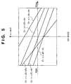
- the degree of freedom in the ⁇ direction is omitted, and the behavior of a light ray is examined in only the X-Z plane, only pixels on a line segment that intersects a plane perpendicular to the Y-axis need be considered. In this manner, by sensing an image, light rays that pass through one point can be collected, and data on a single line segment in the x-u space can be captured by single image sensing.
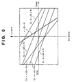
- an image observed from a new arbitrary viewpoint position can be generated (Fig. 7) from the data of the x-u space (Fig. 6).
- an image observed from a new viewpoint position E(X, Z) indicated by an eye mark can be generated by reading out data on a line given by equation (1) from the x-u space.
- Image processes using photo image data do not excel in addition of shades and generation of a shadow by means of virtual illumination. This is because although shades or shadow change in accordance with the three-dimensional pattern of an object, it is hard to reconstruct shades or shadow since photo image data does not have any information pertaining to the geometric shape of the object. That is, a technique for rendering a virtual object on the basis of space data including geometric shape information, rendering shades to be added to that object or rendering a shadow formed by the object is known to those skilled in an image processing field based on geometric shape information (e.g., computer graphics (to be abbreviated as CG hereinafter)), but is unknown in an image processing field using a photo image such as a ray space or the like.
- geometric shape information e.g., computer graphics (to be abbreviated as CG hereinafter)
- One difficulty in generation of a mixed reality space involves changing a real illumination condition and mixing a virtual image with a real space in real time in correspondence with the change in illumination condition.
- the brightness of a real space is measured by a batch method, and the detected illumination condition is reflected in the mixed reality space.
- the present invention has been proposed to solve the conventional problems, and has as its object to provide an image processing method and apparatus suitable for recording space data, which is suitable for generating shades of a virtual object from space data based on a photo image.
- the image processing apparatus and method have a function of rendering shades to be added to a virtual object by a virtual illumination from ray space data, and rendering a shadow by the virtual illumination.
- Fig. 8 shows the arrangement of an image processing system of this embodiment.
- the hardware arrangement shown in Fig. 8 is that of a normal workstation. More specifically, the hardware arrangement itself is the same as that of a normal workstation.
- This system presents a virtual space to the user on a CRT 23.
- the user can freely walk through that virtual space or can manipulate (move, rotate, enlarge, or the like) an object in the virtual space by operating a mouse 28. More specifically, an object in the real space is converted into ray space data on the basis of a photo image, and the converted data is stored in advance in a disk 25.
- a ray space data object image at the moved viewpoint position is generated, as has been explained with reference to Fig. 7.
- This image is mapped on a transparent plate laid out in the virtual space by a texture mapper 24, and the entire virtual space including the mapped image is rendered and displayed on the CRT 23.
- the texture mapper 24 also maps the texture of a shadow to a transparent plate laid out on the bottom portion of the object.
- Fig. 9 explains the recording method of ray space data stored in the disk 25 in this system. That is, as has been explained in Figs. 1 to 7, ray space data expressed by a single line in an (X, u) space corresponds to a photo image that was converted in this line image.
- reference numeral 29 denotes a color camera for obtaining a photo image.
- the camera 29 is mounted on a moving mechanism 30, and a CPU 20 drives the moving mechanism 30 in accordance with a control program (to be described later) to move the position of the camera 29.
- the CPU 20 can detect the moved position of the camera, i.e., the moved viewpoint position (including posture), via the moving mechanism 30.
- Reference numeral 32 denotes an illumination light source. This light source is moved to an arbitrary position via a moving mechanism 31. The moved position is detected by the CPU 20.
- the camera 29 and, especially, the illumination light source 32 are movable to sense shades generated by illuminations (real illuminations) at a plurality of known positions.
- This system generates ray space data with shades in advance on the basis of real shade images. Also, this system holds silhouette images of an object viewed from the light source positions as a shadow image database.
- Fig. 10 explains the principle of capturing shade data.
- reference numeral 100 denotes a real object, which is a circular cone 100 in this example, for the sake of simplicity.
- reference numerals 101 and 102 denote image sensing routes, along which a plurality of image sensing positions are designated.
- the route 101 vertically makes a round of the circular cone 100
- the route 102 horizontally makes a round of the circular cone 100.
- 36 images of the circular cone 100 can be obtained, and these 36 color images are those of the object 100 with shades.
- the sensed images are converted into ray space data by the aforementioned method, and are stored in the disk 25.
- reference numerals 200 and 201 denote moving routes of the illumination light source 32.
- the moving routes 200 and 201 have, e.g., semi-circular arcuated shapes, and are perpendicular to each other. That is, the routes 200 and 201 respectively have 180° moving ranges. Assuming that the light source 32 moves in 10° increments, 18 points of illumination positions for each of the routes 200 and 201 (a total of 36 points) can be obtained.
- the number of illumination positions influences the precision of the shapes of shades and shadow.
- the 10° increment width along each of the horizontal and vertical image sensing routes is merely an example, and the increment width can be arbitrarily increased/decreased as needed.
- ray space data are respectively generated at 36 points of illumination positions. Each ray space data are generated from 36 images.
- RS represents one object
- the object RS can be expressed by RS(L) since it has an argument L of an illumination position.
- Fig. 11 illustrates a state wherein a real image RI i (L) (i is the viewpoint position along the route 101 or 102) obtained by sensing the real object 100 illuminated from the illumination position L by the camera 29 is temporarily stored in the disk 25 and is converted into a ray space data object RS(L), and the converted object is stored.
- Fig. 12 explains a scheme for generating shades upon rendering a virtual image 100' of the object 100 at a certain viewpoint position in a virtual space with a plurality of virtual illuminations.
- three virtual illuminations L 1 , L 2 , L 3 ) are set in the virtual space, and the virtual illuminations (L 1 , L 2 ) are ON, and the virtual illumination (L 3 ) is OFF.
- light shades must be formed on regions 300 and 301 of the surface of the circular cone 100 as a virtual object, and a dense shade on a region 302.
- a virtual image shown in Fig. 13 should be obtained by rendering.
- a ray space data object image RS i (L 1 ) generated at viewpoint position i by setting a light at the illumination position L 1 and a ray space data object image RS i (L 2 ) generated at viewpoint position i by setting a light at the illumination position L 2 can be mixed, as shown in Fig. 14.
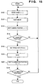
- Fig. 15 is a flow chart for explaining the storage sequence of ray space data according to the first embodiment.
- An image of a real object illuminated by an illumination L n is captured at camera viewpoint position i (step S10), and the captured image is saved (step S12).
- This operation is repeated for all a plurality of predetermined viewpoint positions i (steps S14 and S16).
- the plurality of image data obtained in step S10-S16 are converted into ray space data RS(L n ) of the illumination L n (step S18), and the converted data are saved in the disk 25 (step S20).
- the aforementioned process is repeated for all the illuminations (steps S22 and S24).
- the camera 29 is directed to the real object at each of a plurality of camera viewpoint positions i, the real object is illuminated from each of a plurality of illumination positions L n to capture images of the real object, the captured image data are converted into ray space data RS in units of illumination positions L n , and the converted data are saved in the disk 25 as shown in Fig. 36.
- appropriate ray space data can be obtained by searching the table shown in Fig. 36 based on relative position between the object and the virtual illumination (step S62 of Fig. 18).
- Fig. 16 shows various illumination conditions of the illumination device at the individual illumination positions. These illumination conditions were recorded upon storing ray space data of a real image.
- an application program of this image processing system implements walkthrough in a virtual space, it virtually turns on/off the respective illuminations (virtual illuminations) in accordance with its specifications or by receiving a user instruction upon rendering a virtual object in the virtual space. That is, as has been explained above in relation to Figs. 12 and 13, an image of a virtual object with shades is rendered considering the sum of the contributions of all ON illuminations.
- Fig. 17 shows the control sequence for rendering an image by that application program.
- step S30 viewpoint position i to be rendered is determined. It is checked in step S32 if rendering of ray space data objects pre-stored in correspondence with viewpoint position i of interest is complete. If rendering is not complete, the flow advances to step S34, the table shown in Fig. 16 is searched for virtual illuminations the user (or the application program) wants to turn on. Processes in steps S38 and S40 are done for a ray space object RS(L ON ) corresponding to a designated ON virtual illumination. Note that L ON is the number of a designated ON virtual illumination.
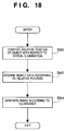
- Fig. 18 shows the rendering process in step S38 in detail.
- steps S60 to S64 process an object RS(L n ). That is, the relative position of the object with respect to the illumination L n is computed in step S60, and object data is acquired by searching the table shown in Fig. 36 in accordance with that relative position in step S62.
- an image of the object RS(L n ) is generated in consideration of illuminance of the illumination L n . For each of R, G, and B values which do not consider any illumination, the pixel value of is changed larger with increasing illuminance value and decreasing distance to the illumination. That is, as shown in Fig.
- step S40 the next ON illumination is referred to in step S40, and the flow returns to step S36 to repeat processes in step S38 ⁇ step S40.
- step S42 Upon completion of the process in step S38 for all ON virtual illuminations, the flow advances to step S42 to compute the sum of pixel values of that pixel computed for the respective virtual illuminations.
- the sum of pixel values can be obtained by simply adding the pixel values of the respective generated images at the corresponding pixel position. It is checked in step S44 if the sum of pixel values computed in step S42 overflows, i.e., exceeds the gamut of the display device (CRT 23). If YES in step S44, a restart process is done in step S46. In the restart process, the illuminance of the virtual illumination is decreased not to cause any overflow, and rendering is redone.
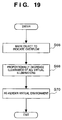
- Fig. 19 shows details of the restart process.
- step S66 objects are marked to indicate overflow.
- step S68 the set illuminance values of all the virtual illuminations (see the table in Fig. 16) are decreased.
- step S70 a virtual environment is rendered again.
- step S44 determines whether overflow is detected. If it is determined in step S44 that no overflow is detected, the next object is referred to in step S50, and the flow returns to step S32. If YES is determined in step S32, ray space data have been processed for all pixels for one frame, and as a result, a virtual image under a condition that two virtual illuminations are ON (Fig. 12) is generated, as shown in, e.g., Fig. 13.
- shades from an illumination at a desired position can be appropriately generated even for a virtual object expressed by IBR data (having no geometric shape information) of the ray space theory or the like.
- the image processing apparatus of this embodiment also has a function of adding a shadow by a virtual illumination in addition to addition of shades by the virtual illumination.
- the shape of a shadow is dominated by the geometric shape of an object and the shape of a plane (to be referred to as a "mapping plane" hereinafter) on which the shadow is projected.
- a mapping plane which the shadow is projected.
- the image processing apparatus of this embodiment generates a shadow image in advance like in shading.
- the mapping plane is generated using a so-called "bounding box" known to those who are skilled in the CG art.
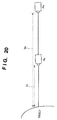
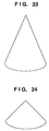
- Figs. 21 and 22 illustrate the principle of a scheme for generating shadow data of the circular cone 100 as an example of a real object.
- the camera 29 is set at a position substantially matching that (including a posture) of the illumination 32 to sense an image of the object 100 illuminated by the illumination 32.
- This image 120 has a shape, as shown in, e.g., Fig. 22, and its silhouette 121 should have a shape approximate to a shadow generated when the object 100 is illuminated by the illumination 32.
- an image is sensed by the camera to record photo images of the object added with shades in the form of ray space data in advance. But upon generating a shadow, an image of the object is sensed to obtain a shadow image.
- the silhouette 121 serves as a basis of a shadow image, and will be simply referred to as an "edge shape" hereinafter.
- a shadow formed by a virtual illumination i.e., a virtual shadow
- the shape of a shadow is influenced by the shape of the mapping plane In addition to the silhouette shape.
- the shadow shape is obtained by projecting the silhouette onto the mapping plane. This projected shape is expressed by an affine transform.
- mapping plane The principle of generating the mapping plane will be explained below.
- a shadow of an object has a shape corresponding to the shape of said object. That is, a shadow is formed within a range corresponding to the shape of an object.
- a feature of this embodiment is to limit the shape (i.e., range) of the mapping plane to that of the mapping plane of the bounding box of an object (virtual object).
- a bounding box that includes all spatial spreads of these virtual images is obtained.
- This box is normally set to have a rectangular parallelopiped shape, and is a box 300 in the example shown in Fig. 25.
- a projected shape 302 of this box is a rectangle, as shown in Fig. 25. This projected shape 302 serves as the mapping plane.
- Fig. 26 shows the control sequence for obtaining the edge shape.
- step S100 the camera 29 and illumination device 32 are set at an arbitrary position L.
- step S102 a real object is illuminated by the illumination 32 at this position L to capture its image.
- step S104 a silhouette is acquired from that image.
- step S106 pixel values in that silhouette are set to be black. Also, the transparency is set at a predetermined value (which does not indicate 100% transparency but allows to see through the surface of the virtual object).
- a process in step S108 is selectively done. That is, if the image sensing plane (the camera position/posture) is not parallel to the projective plane (illumination position/posture), a re-projection process of a shadow image is required. However, in the example shown in Fig. 21 since these planes are not parallel to each other and the angle these planes make is small, errors are expected to be small, and little difference is observed if such re-projection process is not done. When a silhouette is obtained not from a real object but from a virtual object, the perspective viewing volume can be set so that the rendering plane matches the plane of a shadow image.
- a blur process in step S108 considers the fact that an actual shadow is blurred at its edge portion. That is, by adding the blur process, a shadow image can look more natural. Furthermore, by increasing the blur value for a shadow projected at a position farther from the object, the natural feel can be further enhanced.
- this blur process is done for an silhouette image generated from an image of a virtual object, it can be implemented using a jittered viewing volume used upon rendering an image using a depth-of-field effect.
- step S110 the obtained shadow image data is saved.
- step S112 the next image sensing position (illumination position) L+1 is selected, and the processes in steps S100 to S112 are repeated until the processes are done for all the illumination positions.
- step S110 the shadow data is saved in step S110 to be indexed by the relative position value between the illumination and object as shown in Fig. 37.
- silhouettes obtained upon illuminating an object from a plurality of illumination positions can be prepared as shadow images.
- Fig. 27 explains the sequence for rendering a shadow in detail.
- ray space data of a virtual object for which a shadow is to be generated is read out from the memory in step S120.
- step S122 all virtual illuminations that may generate shadows are detected.
- Steps S126 to S134 implement a rendering process of a shadow image formed by an ON illumination of those detected virtual illuminations. More specifically, one ON illumination L is found in step S126.
- step S128, the shape of the mapping plane is computed.
- the shape of the mapping plane can be computed if the geometric shape of the bounding box of a virtual object and the relative position of a light source are given, as described above.
- the geometric shape of the shadow mapping plane can be set so that an arbitrary element in its bounding box has a shadow projected onto that mapping plane.
- the bounding box used to determine the mapping plane can be used to create a simple shadow image in some cases. For example, when light reflected by a ceiling or external light serves as a light source, a very simple shadow image like an ellipse 305 that inscribes the bounding box can be used, as shown in Fig. 28.
- step S130 a shadow image is rendered in correspondence with the relative position of the object with respect to the illumination L.
- the shadow image is indexed by the value of the relative position of the real object (virtual object) with respect to the illumination L (see Fig. 37).
- an image corresponding to shadow data can be read out from the memory using the relative position.
- re-projection and shadow image blur processes are executed.
- step S132 the generated shadow image is mapped on the mapping plane. This mapping is implemented using texture mapping (24 in Fig. 8).
- step S134 the flow returns to step S124 to consider another illumination. If another ON illumination is available, in other words, if shadows formed by a plurality of illuminations may exist, the shadow images generated by the aforementioned scheme are mixed by known CG rendering (in consideration of semi-transparency of an image).
- a shadow formed by an illumination at a desired position can be appropriately generated even for a virtual object expressed by IBR data (having no geometric shape information) of the ray space theory or the like.
- ray space data are obtained by computations, but a RAM or ROM that stores them as a table may be used.
- the display device is not limited to the CRT.
- a lenticular or HMD type display device may be used.
- the above embodiment has exemplified a method of holding in advance images sensed from all possible illumination positions. This is because ray space data objects used have only horizontal disparities but ignore vertical disparities. If a ray space data object can be generated in also consideration of the vertical disparity, an image of an object viewed from a given position of an illumination is generated using that ray space data object, and a silhouette can be rendered. In the ray space theory, not only the horizontal disparity but also vertical disparity can be provided, and such process can be implemented by expanding the aforementioned ray space data process pertaining to the horizontal disparity in the vertical direction. Hence, even when shadow data are not sensed in advance, the silhouette of an image viewed from an illumination position can be generated in real time using ray space data objects, and a shadow can be expressed by re-projecting the generated image.
- shades can be appropriately added to a virtual object defined by space data based on a photo image.
- a shadow can be appropriately mapped on a virtual object defined by space data based on a photo image.
- Fig. 29 is a block diagram showing the overall arrangement of a mixed reality presentation system of this embodiment.
- reference numeral 106 denotes a sensor for measuring the viewpoint position and line-of-sight direction of the user.
- This sensor may be a magnetic or optical sensor provided outside user's body or a sensor attached to an HMD (Head Mounted Display) the user wears.
- the measured viewpoint position and posture are sent to an image generation module 103.
- the image generation module 103 generates a CG image in consideration of the viewpoint position and line of sight of the user.
- an image sensing device 105 uses a video camera or the like for sensing an image of a real space.
- the image sensing device 105 is preferably attached to the head of the user when the viewpoint position and line-of-sight direction of the user change.
- An image input module 104 converts an image sensed by the image sensing device 105 into an object, also generates a depth value of a given object in that image, and passes them on to an image mixing module 102.
- the image mixing module 102 mixes the CG image generated by the image generation module 103 with the video image from the image input module 104.
- occlusion is determined by comparing the depth values of the CG image and video image, and a mask corresponding to a portion to be hidden of a behind object is generated, thus mixing the video and CG images.
- the image generation module 103 receives information that pertains to illumination conditions from a mixed reality space management module 108. That is, the image generation module 103 generates a CG with shades in accordance with the illumination conditions.
- a real illumination device 107 is used to illuminate an object.
- the management module 108 can change the illuminance, illumination direction, and the like of the illumination device.
- the management module 108 converts changed conditions of the illumination device 107 into predetermined parameter values, and passes them on to the image generation module 103.
- Fig. 30 shows an example of the illumination device 107.
- This illumination device has a light control unit 206, which is pivotally supported by a boom 205 via a joint (not shown).
- the boom 205 is fixed to a support shaft 202 via a joint 204.
- the support shaft 202 is pivotally fixed on a rotary stage 203, which is slidably placed on a slide table 201.
- the light control unit can slide, pan, tilt, and rotate.
- the joints, rotary stage, and the like are driven by motors, they can be controlled by a signal from the management unit 108.
- the amount of light can be controlled by controlling the voltage/current to be applied to the light control unit.
- each motor, joint, slide table, and light control unit respectively have a rotary encoder, goniometer, linear distance sensor, and illuminance sensor, their position/posture information can be acquired.
- Fig. 31 explains the relationship among the illumination device 107, management module 108, and image mixing module 103.
- a GUI 120 is a graphic user interface which is displayed on a display device by the management module to change illumination conditions.
- Fig. 32 shows an example of the GUI.
- arrows are control buttons which can be changed by, e.g., a mouse.
- a mouse For example, when the user wants to slide the illumination unit horizontally, he or she clicks one of the right and left arrows with the mouse, and moves the desired arrow in a desired direction.
- the user wants to adjust angle he or she selects the arrow of a portion to be changed by clicking the mouse and rotates it using, e.g., a joystick.
- brightness and color of illumination, and the like can be changed using a keyboard, joystick, or the like.
- the arrow of a portion to be changed may be selected by clicking the mouse and the angle may be set by dragging the mouse in place of the joystick.
- the illumination conditions set by the user via this GUI are sent to a controller 107b in the illumination device 107.
- the controller 107b converts the illumination conditions into drive amounts of the motors and the like of the illumination device 107, and outputs them. In this manner, the illumination device 107 is set at illuminance and the like set by the user via the GUI.
- the illumination conditions set via the GUI are converted into illumination condition parameters, e.g., angle, specular, ambient, position, diffusion, and the like defined by a space language used in the generation module 103. Note that these parameter values are determined in advance by experiments under various illumination conditions.
- the image generation module 103 sets the received parameter values in a rendering routine.
- Fig. 33 shows the control sequence of the mixed reality space management module 108
- Fig. 34 shows the control sequence of the image generation module 103.
- the mixed reality space management module 108 and image generation module 103 are program modules and communicate with each other via an API (Application Program Interface) of a predetermined protocol. More specifically, the management module 108 monitors in step S102 if the user has changed illumination conditions using the GUI. If YES in step S102, the module 108 computes various controlled variables for the illumination unit in step S104, and send them to the controller 107b of the illumination device 107 in step S106. The module 108 generates illumination parameters such as angle in step S108, and the like and send them to the image generation module 103 via an API in step S110. In step S112, the module 108 generates an event and informs the module 103 of the event.
- API Application Program Interface
- the image generation module 103 waits for generation of an event (step S202). If an event is generated, the module 103 confirms in step S204 if the event is an illumination condition change event, and receives illumination parameters via an API in step S206. In step S208, the module 103 replaces parameters in the rendering routine by the received parameters. In step S210, the module 103 renders a CG image in accordance with the received parameters. The rendered CG image has shades or the like, which have been changed in accordance with the changed illumination conditions.
- An illumination device 3802 has light source3803, control buttons 3804 for adjusting illumination brightness and manipulator 3805 for turning the illumination device in horizontal direction around the axis 3806.
- the illumination (light source) is at a position "n”. Accordingly, an object image 3801 is rendered based on ray space data RS(Ln).
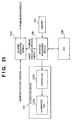
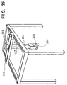
- Fig. 35 explains a modification of an illumination unit 107a.
- the light control unit 206 is supported by a tilt unit 301, which is axially supported to be free to tilt.
- the tilt unit 301 is vertically movable.
- a support shaft 304 is connected to a motor 303 and can be rotated to pan the light control unit.
- the support shaft 304 is parallelly movable along a slide table 302.
- the slide table 302 is movable in a direction perpendicular to the moving direction of the shaft 304.
- the GUI is used to change illumination conditions.
- hardware devices such as a volume, slide switch, joystick, and the like may be used. When such hardware devices are used, output signals from these devices must be sent to the apparatus having the management module.
- the illumination conditions are changed under the control of a computer.
- the present invention is not limited to such specific control.
- the present invention can be applied when the illumination conditions are manually changed.
- condition change values on the GUI 120 may be read by the controller 107b in a software manner.
- the need for the rotary encoder in the above embodiment can be obviated.
- an illuminance sensor, a sensor for detecting illumination direction, and the like are provided, and these sensor outputs are supplied to the management module.
- illumination program parameters are pre-stored in a predetermined memory 121, but may be computed in real time on the basis of the detected illuminance, illumination direction, and the like.
- conversion formulas for deriving parameter values from the detection values of the illumination conditions may be pre-stored in the memory, and parameters may be computed using these conversion formulas in real time.
- the illumination conditions of a virtual image can be acquired in real time in correspondence with changes in real illumination. For this reason, deviation of image quality between real and virtual images due to structural differences of the illumination conditions can be minimized.
- an image processing apparatus for describing a real image as a virtual object using space data formed based on a photo image of the real object, and generating a virtual image of the virtual object using the space data.
- the image processing apparatus captures the photo image of the real object from a real camera viewpoint position while illuminating the real object by an illumination light source placed at a real illumination position.
- the captured photo image is converted into space data in the form of an object for each pixel, and the space data is stored in a memory together with various illumination conditions at the real illumination position to allow a search at a later time.
Landscapes
- Engineering & Computer Science (AREA)
- Computer Graphics (AREA)
- Physics & Mathematics (AREA)
- General Physics & Mathematics (AREA)
- Theoretical Computer Science (AREA)
- Image Generation (AREA)
- Processing Or Creating Images (AREA)
Abstract
Description
Claims (74)
- An image processing method for describing a real image as a virtual object using space data formed based on a photo image of the real object, and generating a virtual image of the virtual object using the space data, comprising the steps of:capturing the photo image of the real object from a real camera viewpoint position while illuminating the real object by an illumination light source placed at a real illumination position;converting the photo image into space data in the form of an object; andstoring the space data in a memory together with various illumination conditions at the real illumination position to allow a search at a later time.
- The method according to claim 1, wherein the illumination position of the illumination light source is set at a plurality of different positions, and position information and an illumination condition at each illumination position are stored in the memory together with corresponding space data.
- The method according to claim 1, wherein the camera viewpoint position is set at a plurality of different positions, and space data obtained at each viewpoint position is stored together with the viewpoint position information.
- The method according to claim 1, wherein the space data is ray space theory data.
- The method according to claim 1, wherein the illumination condition is varied in a plurality of ways per illumination position, and space data corresponding to the individual illumination conditions are stored in the memory.
- An image processing method for describing a real image as a virtual object using space data formed based on a photo image of the real object, and generating a virtual image of the virtual object using the space data, comprising the steps of:storing space data generated from a photo image together with a real camera viewpoint position, and an illumination position and illumination condition of a real illumination light source;generating coordinates of a virtual image of an object at a user viewpoint position on the basis of the real camera viewpoint position and the space data; andcorrecting pixel values of the virtual image on the basis of the real illumination position and real illumination condition of the real illumination light source, and a virtual illumination position and virtual illumination condition set for a virtual illumination light source.
- The method according to claim 6, wherein the illumination position of the real illumination light source is set at a plurality of different positions, and position information and an illumination condition at each illumination position are stored in the memory together with corresponding space data.
- The method according to claim 6, wherein the real camera viewpoint position is set at a plurality of different positions, and space data obtained at each viewpoint position is stored together with the viewpoint position information.
- The method according to claim 6, wherein the space data is ray space theory data.
- The method according to claim 6, further comprising the step of changing and setting an illumination condition of the virtual illumination light source to be an arbitrary value, and wherein the correction step includes the step of correcting the pixel values in accordance with the changed illumination condition.
- The method according to claim 6, wherein when a plurality of virtual light sources are ON at the same time, a plurality of correction results which are corrected in accordance with the respective virtual illumination light sources are added for one pixel position to obtain a final pixel value.
- The method according to claim 6, wherein when some of a plurality of virtual light sources are ON at the same time, a plurality of correction results which are corrected in accordance with the respective ON virtual illumination light sources are added for one pixel position to obtain a final pixel value.
- The method according to claim 6, further comprising the steps of:determining if the corrected pixel value saturates; andvirtually changing illumination conditions of some or all of the virtual light sources in a direction to decrease luminance or illuminance of an illumination when the pixel value saturates, and
wherein the correction step is executed again in accordance with the changed illumination condition. - The method according to claim 6, wherein the illumination condition includes information indicating whether or not an illumination is turned on.
- The method according to claim 6, wherein the illumination condition includes illuminance or luminance.
- The method according to claim 6, wherein the illumination condition includes a relative position between the virtual light source and object.
- The method according to claim 6, wherein the illumination condition includes color of illumination.
- An image processing apparatus for describing a real image as a virtual object using space data formed based on a photo image of the real object, and generating a virtual image of the virtual object using the space data, comprising:means for capturing the photo image of the real object from a real camera viewpoint position while illuminating the real object by an illumination light source placed at a real illumination position;conversion means for converting the photo image into space data in the form of an object for each pixel; andmeans for storing the space data in a memory together with various illumination conditions at the real illumination position to allow a search at a later time.
- The apparatus according to claim 18, wherein the illumination position of the illumination light source is set at a plurality of different positions, and position information and an illumination condition at each illumination position are stored in the memory together with corresponding space data.
- The apparatus according to claim 18, wherein the camera viewpoint position is set at a plurality of different positions, and space data obtained at each viewpoint position is stored together with the viewpoint position information.
- The apparatus according to claim 18, wherein the space data is ray space theory data.
- The apparatus according to claim 18, wherein the illumination condition is varied in a plurality of ways per illumination position, and space data corresponding to the individual illumination conditions are stored in the memory.
- An image processing apparatus for describing a real image as a virtual object using space data formed based on a photo image of the real object, and generating a virtual image of the virtual object using the space data, comprising:means for storing space data in the form of an object for each pixel of a photo image together with a real camera viewpoint position, and an illumination position and illumination condition of a real illumination light source;generation means for generating coordinates of a virtual image of an object at a user viewpoint position on the basis of the real camera viewpoint position and the space data; andcorrection means for correcting pixel values of the virtual image on the basis of the real illumination position and real illumination condition of the real illumination light source, and a virtual illumination position and virtual illumination condition set for a virtual illumination light source.
- The apparatus according to claim 23, wherein the illumination position of the real illumination light source is set at a plurality of different positions, and position information and an illumination condition at each illumination position are stored in the memory together with corresponding space data.
- The apparatus according to claim 23, wherein the real camera viewpoint position is set at a plurality of different positions, and space data obtained at each viewpoint position is stored together with the viewpoint position information.
- The apparatus according to claim 23, wherein the space data is ray space theory data.
- The apparatus according to claim 23, further comprising means for changing and setting an illumination condition of the virtual illumination light source to be arbitrary values, and wherein said correction means corrects the pixel values in accordance with the changed illumination condition.
- The apparatus according to claim 23, wherein when a plurality of virtual light sources are ON at the same time, a plurality of correction results which are corrected in accordance with the respective virtual illumination light sources are added for one pixel position to obtain a final pixel value.
- The apparatus according to claim 23, wherein when some of a plurality of virtual light sources are ON at the same time, a plurality of correction results which are corrected in accordance with the respective ON virtual illumination light sources are added for one pixel position to obtain a final pixel value.
- The apparatus according to claim 23, further comprising:means for determining if the corrected pixel value saturates; andmeans for virtually changing illumination conditions of some or all of the virtual light sources in a direction to decrease luminance or illuminance of an illumination when the pixel value saturates, and
wherein said correction means is executed again in accordance with the changed illumination condition. - The apparatus according to claim 23, wherein the illumination condition includes information indicating whether or not an illumination is turned on.
- The apparatus according to claim 23, wherein the illumination condition includes illuminance or luminance.
- The apparatus according to claim 23, wherein the illumination condition includes a relative position between the virtual light source and object.
- The apparatus according to claim 23, wherein the illumination condition includes color of illumination.
- An image processing method for generating a shadow image of a virtual object itself in a virtual space, comprising the steps of:sensing an image of a real object by a camera while illuminating the real object corresponding to the virtual object from a light source at a predetermined illumination position;extracting a silhouette of the real object from the image of the real object;adding preferred image information as a shadow to pixels in the silhouette; andstoring the silhouette image together with position information of the light source, the silhouette image being able to be found by search and retrieved at a later time.
- The method according to claim 35, wherein the preferred image information includes a predetermined black pixel value and a predetermined transparency value.
- The method according to claim 35, wherein the silhouette image undergoes a blur process.
- The method according to claim 37, wherein the degree of blur is changed in correspondence with distance from the virtual object to a virtual light source.
- The method according to claim 35, wherein a viewpoint position of the camera matches the position of the illumination light source.
- An image processing method for generating a shadow image of a virtual object itself in a virtual space, comprising the steps of:storing space data of the virtual object, a shadow image of a real object corresponding to the virtual object, and a position of an illumination light source upon forming the shadow image in a predetermined memory;reading out the shadow image from the memory in accordance with a position of a virtual illumination, and a relative position of the virtual object; andmapping the readout shadow image on a predetermined mapping plane.
- The method according to claim 40, wherein the mapping plane is determined on the basis of a bounding box of the virtual object.
- The method according to claim 40, further comprising the step of changing and setting an illumination condition of the virtual illumination light source to be an arbitrary value, and wherein the correction step includes the step of correcting the pixel values in accordance with the changed illumination condition.
- The method according to claim 40, wherein when a plurality of virtual light sources are ON at the same time, a plurality of correction results which are corrected in accordance with the respective virtual illumination light sources are added for one pixel position to obtain a final pixel value.
- The method according to claim 40, wherein when some of a plurality of virtual light sources are ON at the same time, a plurality of correction results which are corrected in accordance with the respective ON virtual illumination light sources are added for one pixel position to obtain a final pixel value.
- The method according to claim 40, wherein when the illumination is located at a high-level position, a mapping plane with a simple shape is generated.
- An image processing apparatus for generating a shadow image of a virtual object itself in a virtual space, comprising:means for sensing an image of a real object by a camera while illuminating the real object corresponding to the virtual object from a light source at a predetermined illumination position;means for extracting a silhouette of the real object from the image of the real object;means for adding preferred image information as a shadow to pixels in the silhouette; andmeans for storing the edge image together with position information of the light source, the silhouette image being able to be found by search and retrieved at a later time.
- The apparatus according to claim 46, wherein the preferred image information includes a predetermined black pixel value and a predetermined transparency value.
- The apparatus according to claim 46, wherein when the viewpoint position of the camera is different from the position of the light source, the silhouette image is corrected by re-projecting the silhouette image to have the position of the light source as a viewpoint position.
- The apparatus according to claim 46, further comprising means for performing a blur process of the silhouette image.
- The apparatus according to claim 49, wherein the degree of blur is changed in correspondence with distance from the virtual object to a virtual light source.
- The apparatus according to claim 46, wherein a viewpoint position of the camera matches the position of the illumination light source.
- An image processing apparatus for generating a shadow image of a virtual object itself in a virtual space, comprising the steps of:means for storing space data of the virtual object, a shadow image of a real object corresponding to the virtual object, and a position of an illumination light source upon forming the shadow image in a predetermined memory;means for reading out the shadow image from the memory in accordance with a position of a virtual illumination, and a relative position of the virtual object; andmeans for mapping the readout shadow image on a predetermined mapping plane.
- The apparatus according to claim 52, wherein the mapping plane is determined on the basis of a bounding box of the virtual object.
- The apparatus according to claim 52, further comprising means for changing and setting an illumination condition of the virtual illumination light source to be an arbitrary value, and wherein said correction means corrects the pixel values in accordance with the changed illumination condition.
- The apparatus according to claim 52, wherein when a plurality of virtual light sources are ON at the same time, a plurality of correction results which are corrected in accordance with the respective virtual illumination light sources are added for one pixel position to obtain a final pixel value.
- The apparatus according to claim 52, wherein when some of a plurality of virtual light sources are ON at the same time, a plurality of correction results which are corrected in accordance with the respective ON virtual illumination light sources are added for one pixel position to obtain a final pixel value.
- The apparatus according to claim 52, wherein when the illumination is located at a high-level position, a mapping plane with a simple shape is generated.
- An image processing method for generating a shadow image of a virtual object itself in a virtual space, comprising the steps of:extracting a silhouette of the virtual object viewed from a predetermined illumination position on the basis of space data which expresses the virtual object;adding preferred image information as a shadow to pixels in the silhouette; andmapping the silhouette image on a predetermined mapping plane.
- An image processing apparatus for generating a shadow image of a virtual object itself in a virtual space, comprising:means for extracting a silhouette of the virtual object viewed from a predetermined illumination position on the basis of space data which expresses the virtual object;means for adding preferred image information as a shadow to pixels in the silhouette; andmeans for mapping the silhouette image on a predetermined mapping plane.
- An image processing apparatus for mixing a virtual space with a real space illuminated by a real illumination device, and presenting the mixed space, comprising:change means for changing an illumination condition of the illumination device;first setting means for setting an illumination program parameter value corresponding to a value of the changed illumination condition;rendering means for rendering a virtual image using a predetermined illumination condition program parameter, and mixing the virtual image with the real space; andsecond setting means for setting, in a rendering routine of the virtual image of said rendering means, the illumination condition program parameter set by said setting means in correspondence with the illumination condition changed by said change means.
- The apparatus according to claim 60, wherein the illumination condition includes one of illuminance, color, and an illumination direction.
- The apparatus according to claim 60, wherein said change means comprises GUI means operated by a user to display control buttons for graphically changing illuminance, color, and an illumination direction of the illumination device on a display screen.
- The apparatus according to claim 60, wherein said change means comprises GUI means operated by a user, and said GUI means displays an image that simplifies the illumination device and allows the user to instruct to change a given illumination condition by designating a portion to be adjusted in the image using a pointing device.
- The apparatus according to claim 60, wherein said first setting means includes means for reading out a parameter pre-stored in a predetermined memory.
- An image processing method for mixing a virtual space with a real space illuminated by a real illumination device, comprising:the step of changing an illumination condition of the illumination device;the first setting step of setting an illumination program parameter value corresponding to a value of the changed illumination condition;the step of rendering a virtual image using a predetermined illumination condition program parameter, and mixing the virtual image with the real space; andthe second setting step of setting, in a rendering routine of the virtual image, the illumination condition program parameter set in correspondence with the illumination condition changed in the change step.
- The method according to claim 65, wherein the first setting step includes the step of reading out a parameter pre-stored in a predetermined memory.
- The method according to claim 65, wherein the change step includes the step of displaying a GUI operated by a user to display control buttons for graphically changing illuminance, color, and an illumination direction of the illumination device on a display screen.
- The method according to claim 65, wherein the change step includes the step of displaying a GUI operated by a user, and the GUI displays an image that simplifies the illumination device and allows the user to instruct to change a given illumination condition by designating a portion to be adjusted in the image using a pointing device.
- A storage medium that stores a control program for making a computer execute an image process for describing a real image as a virtual object using space data formed based on a photo image of the real object, and generating a virtual image of the virtual object using the space data, said control program including:a code of the capture step of capturing the photo image of the real object from a real camera viewpoint position while illuminating the real object by an illumination light source placed at a real illumination position;a code of the conversion step of converting the photo image into space data in the form of an object; anda code of the storage step of storing the space data in a memory to allow a search together with various illumination conditions at the real illumination position.
- A storage medium that stores a control program for making a computer execute an image process for describing a real image as a virtual object using space data formed based on a photo image of the real object, and generating a virtual image of the virtual object using the space data, said control program including:a code of the storage step of storing space data generated from a photo image together with a real camera viewpoint position, and an illumination position and illumination condition of a real illumination light source;a code of the generation step of generating coordinates of a virtual image of an object at a user viewpoint position on the basis of the real camera viewpoint position and the space data; anda code of the correction step of correcting pixel values of the virtual image on the basis of the real illumination position and real illumination condition of the real illumination light source, and a virtual illumination position and virtual illumination condition set for a virtual illumination light source.
- A storage medium that stores a control program for making a computer execute an image process for generating a shadow image of a virtual object itself in a virtual space, said control program including:a code of the image sensing step of sensing an image of a real object by a camera while illuminating the real object corresponding to the virtual object from a light source at a predetermined illumination position;a code of the extraction step of extracting a silhouette of the real object from the image of the real object;a code of the addition step of adding preferred image information as a shadow to pixels in the silhouette; anda code of the storage step of storing the silhouette image together with position information of the light source, the silhouette image being able to be found by search and retrieved at a later time.
- A storage medium that stores a control program for making a computer execute an image process for generating a shadow image of a virtual object itself in a virtual space, said control program including:a code of the storage step of storing space data of the virtual object, a shadow image of a real object corresponding to the virtual object, and a position of an illumination light source upon forming the shadow image in a predetermined memory;a code of the read-out step of reading out the shadow image from the memory in accordance with a position of a virtual illumination, and a relative position of the virtual object; anda code of the mapping step of mapping the readout shadow image on a predetermined mapping plane.
- A storage medium that stores a control program for making a computer execute an image process for generating a shadow image of a virtual object itself in a virtual space, said control program including:a code of the extraction step of extracting a silhouette of the virtual object viewed from a predetermined illumination position on the basis of space data which expresses the virtual object;a code of the addition step of adding preferred image information as a shadow to pixels in the silhouette; anda code of the mapping step of mapping the silhouette image on a predetermined mapping plane.
- A storage medium that stores a control program for making a computer execute an image process for generating a shadow image of a virtual object itself in a virtual space, said control program including:a code of the step of changing an illumination condition of the illumination device;a code of the first setting step of setting an illumination program parameter value corresponding to a value of the changed illumination condition;a code of the step of rendering a virtual image using a predetermined illumination condition program parameter, and mixing the virtual image with the real space; anda code of the second setting step of setting, in a rendering routine of the virtual image, the illumination condition program parameter set in correspondence with the illumination condition changed in the change step.
Applications Claiming Priority (6)
| Application Number | Priority Date | Filing Date | Title |
|---|---|---|---|
| JP22395999 | 1999-08-06 | ||
| JP22395899A JP3387856B2 (en) | 1999-08-06 | 1999-08-06 | Image processing method, image processing device, and storage medium |
| JP22395899 | 1999-08-06 | ||
| JP22395999A JP3392078B2 (en) | 1999-08-06 | 1999-08-06 | Image processing method, image processing device, and storage medium |
| JP24677099A JP3486575B2 (en) | 1999-08-31 | 1999-08-31 | Mixed reality presentation apparatus and method, and storage medium |
| JP24677099 | 1999-08-31 |
Publications (2)
| Publication Number | Publication Date |
|---|---|
| EP1074943A2 true EP1074943A2 (en) | 2001-02-07 |
| EP1074943A3 EP1074943A3 (en) | 2004-03-24 |
Family
ID=27330836
Family Applications (1)
| Application Number | Title | Priority Date | Filing Date |
|---|---|---|---|
| EP00103803A Withdrawn EP1074943A3 (en) | 1999-08-06 | 2000-02-23 | Image processing method and apparatus |
Country Status (2)
| Country | Link |
|---|---|
| US (3) | US6930685B1 (en) |
| EP (1) | EP1074943A3 (en) |
Cited By (3)
| Publication number | Priority date | Publication date | Assignee | Title |
|---|---|---|---|---|
| US8754891B2 (en) | 2010-08-18 | 2014-06-17 | Industrial Technology Research Institute | Method for image processing and an apparatus thereof |
| TWI462053B (en) * | 2010-08-18 | 2014-11-21 | Ind Tech Res Inst | Method and apparatus for image processing |
| CN104346831A (en) * | 2014-11-01 | 2015-02-11 | 长春理工大学 | Method for approximately drawing soft shadow of three-dimensional scene |
Families Citing this family (32)
| Publication number | Priority date | Publication date | Assignee | Title |
|---|---|---|---|---|
| WO2002075658A1 (en) * | 2001-03-12 | 2002-09-26 | Center For Advanced Science And Technology Incubation, Ltd. | Stereostructure verification supporting apparatus, stereostructure verification supporting method, and program |
| US7239345B1 (en) * | 2001-10-12 | 2007-07-03 | Worldscape, Inc. | Camera arrangements with backlighting detection and methods of using same |
| JP4115188B2 (en) * | 2002-07-19 | 2008-07-09 | キヤノン株式会社 | Virtual space drawing display device |
| US7146036B2 (en) * | 2003-02-03 | 2006-12-05 | Hewlett-Packard Development Company, L.P. | Multiframe correspondence estimation |
| US7969409B2 (en) * | 2004-02-18 | 2011-06-28 | Rafal Jan Krepec | Camera assisted pen tablet |
| US7218324B2 (en) * | 2004-06-18 | 2007-05-15 | Mitsubishi Electric Research Laboratories, Inc. | Scene reflectance functions under natural illumination |
| US7663638B2 (en) * | 2005-11-23 | 2010-02-16 | Autodesk, Inc. | Stroked fill |
| US7616201B2 (en) * | 2005-11-23 | 2009-11-10 | Autodesk, Inc. | Casting shadows |
| US7603621B2 (en) * | 2006-01-25 | 2009-10-13 | Microsoft Corporation | Computer interface for illiterate and near-illiterate users |
| US7714866B2 (en) * | 2006-07-19 | 2010-05-11 | Autodesk, Inc. | Rendering a simulated vector marker stroke |
| JP4804256B2 (en) * | 2006-07-27 | 2011-11-02 | キヤノン株式会社 | Information processing method |
| US7777745B2 (en) * | 2007-04-27 | 2010-08-17 | Autodesk, Inc. | Edge effect |
| JP4764381B2 (en) * | 2007-06-05 | 2011-08-31 | 株式会社コナミデジタルエンタテインメント | Image processing apparatus, image processing method, and program |
| US20090153550A1 (en) * | 2007-12-18 | 2009-06-18 | Disney Enterprises, Inc. | Virtual object rendering system and method |
| CN101458823B (en) * | 2008-12-19 | 2011-08-31 | 北京航空航天大学 | Real-time lighting drawing method under virtual stage environment |
| JP5762015B2 (en) * | 2011-01-27 | 2015-08-12 | キヤノン株式会社 | Image processing apparatus, image processing method, and program |
| JP2012243147A (en) * | 2011-05-20 | 2012-12-10 | Nintendo Co Ltd | Information processing program, information processing device, information processing system, and information processing method |
| WO2012171116A1 (en) | 2011-06-16 | 2012-12-20 | Rafal Jan Krepec | Visual feedback by identifying anatomical features of a hand |
| US20140160155A1 (en) * | 2011-08-30 | 2014-06-12 | Hewlett-Packard Development Company, L.P. | Inserting an Object into an Image |
| JP2013127774A (en) * | 2011-11-16 | 2013-06-27 | Canon Inc | Image processing device, image processing method, and program |
| US8872853B2 (en) | 2011-12-01 | 2014-10-28 | Microsoft Corporation | Virtual light in augmented reality |
| US9311751B2 (en) | 2011-12-12 | 2016-04-12 | Microsoft Technology Licensing, Llc | Display of shadows via see-through display |
| KR101419044B1 (en) * | 2013-06-21 | 2014-07-11 | 재단법인 실감교류인체감응솔루션연구단 | Method, system and computer-readable recording medium for displaying shadow of 3d virtual object |
| US9652892B2 (en) | 2013-10-29 | 2017-05-16 | Microsoft Technology Licensing, Llc | Mixed reality spotlight |
| CN104077802B (en) * | 2014-07-16 | 2018-01-05 | 四川蜜蜂科技有限公司 | The method that enhancing virtual scene real-time simulation image is shown |
| US9646413B2 (en) * | 2014-08-27 | 2017-05-09 | Robert Bosch Gmbh | System and method for remote shadow rendering in a 3D virtual environment |
| US9914222B2 (en) | 2015-02-05 | 2018-03-13 | Canon Kabushiki Kaisha | Information processing apparatus, control method thereof, and computer readable storage medium that calculate an accuracy of correspondence between a model feature and a measurement data feature and collate, based on the accuracy, a geometric model and an object in an image |
| US20160350967A1 (en) * | 2015-06-01 | 2016-12-01 | Cable Television Laboratories, Inc. | Dynamic adjustments for augmented, mixed and virtual reality presentations |
| KR102502449B1 (en) * | 2015-10-05 | 2023-02-22 | 삼성전자주식회사 | Device and method to display illumination |
| US10281378B2 (en) * | 2016-05-05 | 2019-05-07 | Honeywell Federal Manufacturing & Technologies, Llc | System and method for testing true stress and true strain |
| US10354573B2 (en) * | 2017-07-25 | 2019-07-16 | Lenovo (Singapore) Pte Ltd | Screen color calibration |
| CN115965672B (en) * | 2021-10-09 | 2025-12-30 | 北京字节跳动网络技术有限公司 | Methods, devices, equipment and media for displaying three-dimensional objects |
Family Cites Families (44)
| Publication number | Priority date | Publication date | Assignee | Title |
|---|---|---|---|---|
| US5329431A (en) * | 1986-07-17 | 1994-07-12 | Vari-Lite, Inc. | Computer controlled lighting system with modular control resources |
| JPS644871A (en) | 1987-06-27 | 1989-01-10 | Aisin Seiki | Different kind light source illuminance difference stereo image recognizing device |
| JPH01281574A (en) | 1988-05-09 | 1989-11-13 | Canon Inc | Method and device for image processing |
| FR2661061B1 (en) * | 1990-04-11 | 1992-08-07 | Multi Media Tech | METHOD AND DEVICE FOR MODIFYING IMAGE AREA. |
| US5185638A (en) * | 1991-04-26 | 1993-02-09 | International Business Machines Corporation | Computer controlled, multiple angle illumination system |
| JPH04358291A (en) * | 1991-06-04 | 1992-12-11 | Hitachi Ltd | How to change color image |
| JP3236362B2 (en) | 1992-09-22 | 2001-12-10 | 株式会社資生堂 | Skin surface shape feature extraction device based on reconstruction of three-dimensional shape from skin surface image |
| US5422653A (en) * | 1993-01-07 | 1995-06-06 | Maguire, Jr.; Francis J. | Passive virtual reality |
| JPH06223201A (en) * | 1993-01-22 | 1994-08-12 | Matsushita Electric Ind Co Ltd | Parallel image generator |
| US5644324A (en) * | 1993-03-03 | 1997-07-01 | Maguire, Jr.; Francis J. | Apparatus and method for presenting successive images |
| US5815411A (en) * | 1993-09-10 | 1998-09-29 | Criticom Corporation | Electro-optic vision system which exploits position and attitude |
| JPH06274579A (en) | 1993-03-17 | 1994-09-30 | Nippon Hoso Kyokai <Nhk> | 3D still image file system |
| JPH06307833A (en) | 1993-04-23 | 1994-11-04 | Nippon Steel Corp | Uneven shape recognition device |
| JPH0727531A (en) | 1993-07-14 | 1995-01-27 | Hitachi Denshi Ltd | Inspection area recognition method in appearance shape inspection device |
| US5729672A (en) * | 1993-07-30 | 1998-03-17 | Videologic Limited | Ray tracing method and apparatus for projecting rays through an object represented by a set of infinite surfaces |
| US6690338B1 (en) * | 1993-08-23 | 2004-02-10 | Francis J. Maguire, Jr. | Apparatus and method for providing images of real and virtual objects in a head mounted display |
| US6411266B1 (en) * | 1993-08-23 | 2002-06-25 | Francis J. Maguire, Jr. | Apparatus and method for providing images of real and virtual objects in a head mounted display |
| US5565745A (en) * | 1994-01-04 | 1996-10-15 | Huether; James L. | Communications protocol |
| JP3013690B2 (en) | 1994-03-24 | 2000-02-28 | 日本鋼管株式会社 | Method and apparatus for measuring three-dimensional curved surface shape |
| US5519826A (en) * | 1994-04-29 | 1996-05-21 | Atari Games Corporation | Stop motion animation system |
| JPH0896165A (en) * | 1994-09-29 | 1996-04-12 | Fujitsu Ltd | Image generating method and image generating apparatus |
| JP3309615B2 (en) * | 1994-12-21 | 2002-07-29 | キヤノン株式会社 | Image observation apparatus and binocular image observation apparatus using the same |
| JPH08210820A (en) | 1995-02-01 | 1996-08-20 | Hitachi Denshi Ltd | Method and apparatus for recognizing inspected part in appearance inspection apparatus for component mounting board |
| US5736986A (en) * | 1995-07-14 | 1998-04-07 | Sever, Jr.; Frank | Virtual reality mental conditioning medium |
| US5629587A (en) * | 1995-09-26 | 1997-05-13 | Devtek Development Corporation | Programmable lighting control system for controlling illumination duration and intensity levels of lamps in multiple lighting strings |
| US5737031A (en) * | 1996-07-30 | 1998-04-07 | Rt-Set | System for producing a shadow of an object in a chroma key environment |
| US6064749A (en) * | 1996-08-02 | 2000-05-16 | Hirota; Gentaro | Hybrid tracking for augmented reality using both camera motion detection and landmark tracking |
| US6847336B1 (en) * | 1996-10-02 | 2005-01-25 | Jerome H. Lemelson | Selectively controllable heads-up display system |
| US5864640A (en) * | 1996-10-25 | 1999-01-26 | Wavework, Inc. | Method and apparatus for optically scanning three dimensional objects using color information in trackable patches |
| JPH10255081A (en) * | 1997-03-10 | 1998-09-25 | Canon Inc | Image processing method and image processing apparatus |
| JPH10255069A (en) * | 1997-03-10 | 1998-09-25 | Canon Inc | Image processing system |
| JP3749369B2 (en) * | 1997-03-21 | 2006-02-22 | 株式会社竹中工務店 | Hand pointing device |
| JPH11134519A (en) | 1997-10-31 | 1999-05-21 | Atr Chino Eizo Tsushin Kenkyusho:Kk | Virtual light source control device |
| US6166744A (en) * | 1997-11-26 | 2000-12-26 | Pathfinder Systems, Inc. | System for combining virtual images with real-world scenes |
| JP3868621B2 (en) * | 1998-03-17 | 2007-01-17 | 株式会社東芝 | Image acquisition apparatus, image acquisition method, and recording medium |
| US6317139B1 (en) * | 1998-03-25 | 2001-11-13 | Lance Williams | Method and apparatus for rendering 3-D surfaces from 2-D filtered silhouettes |
| US6628298B1 (en) * | 1998-07-17 | 2003-09-30 | The Regents Of The University Of California | Apparatus and method for rendering synthetic objects into real scenes using measurements of scene illumination |
| US6452593B1 (en) * | 1999-02-19 | 2002-09-17 | International Business Machines Corporation | Method and system for rendering a virtual three-dimensional graphical display |
| JP2002175539A (en) * | 2000-12-06 | 2002-06-21 | Data Keekibeeka Kk | Image processing method, program thereof, and image processing apparatus |
| US7044613B2 (en) * | 2001-06-08 | 2006-05-16 | University Of Southern California | Realistic scene illumination reproduction |
| US6778180B2 (en) * | 2001-09-28 | 2004-08-17 | The United States Of America As Represented By The Administrator Of The National Aeronautics And Space Administration | Video image tracking engine |
| US7138997B2 (en) * | 2002-06-28 | 2006-11-21 | Autodesk, Inc. | System for physical rotation of volumetric display enclosures to facilitate viewing |
| JP2006507585A (en) * | 2002-11-15 | 2006-03-02 | ワーナー・ブロス・エンターテイメント・インコーポレーテッド | Reverse rendering method for digital modeling |
| US7091973B1 (en) * | 2003-06-20 | 2006-08-15 | Jonathan Michael Cohen | Apparatus and method for estimating reflected radiance under complex distant illumination |
-
2000
- 2000-02-23 EP EP00103803A patent/EP1074943A3/en not_active Withdrawn
- 2000-02-25 US US09/512,836 patent/US6930685B1/en not_active Expired - Lifetime
-
2005
- 2005-04-27 US US11/115,162 patent/US20050190181A1/en not_active Abandoned
- 2005-04-27 US US11/115,344 patent/US20050195332A1/en not_active Abandoned
Cited By (4)
| Publication number | Priority date | Publication date | Assignee | Title |
|---|---|---|---|---|
| US8754891B2 (en) | 2010-08-18 | 2014-06-17 | Industrial Technology Research Institute | Method for image processing and an apparatus thereof |
| TWI462053B (en) * | 2010-08-18 | 2014-11-21 | Ind Tech Res Inst | Method and apparatus for image processing |
| CN104346831A (en) * | 2014-11-01 | 2015-02-11 | 长春理工大学 | Method for approximately drawing soft shadow of three-dimensional scene |
| CN104346831B (en) * | 2014-11-01 | 2017-02-22 | 长春理工大学 | Method for approximately drawing soft shadow of three-dimensional scene |
Also Published As
| Publication number | Publication date |
|---|---|
| EP1074943A3 (en) | 2004-03-24 |
| US6930685B1 (en) | 2005-08-16 |
| US20050190181A1 (en) | 2005-09-01 |
| US20050195332A1 (en) | 2005-09-08 |
Similar Documents
| Publication | Publication Date | Title |
|---|---|---|
| US6930685B1 (en) | Image processing method and apparatus | |
| ES2951587T3 (en) | A system for mixing or compositing computer-generated 3D objects and a video signal from a film camera in real time | |
| US11328436B2 (en) | Using camera effect in the generation of custom synthetic data for use in training an artificial intelligence model to produce an image depth map | |
| US6323862B1 (en) | Apparatus for generating and interactively viewing spherical image data and memory thereof | |
| JP5093053B2 (en) | Electronic camera | |
| AU2011312140C1 (en) | Rapid 3D modeling | |
| US20050128196A1 (en) | System and method for three dimensional modeling | |
| EP0782100A2 (en) | Three-dimensional shape extraction apparatus and method | |
| US20020113865A1 (en) | Image processing method and apparatus | |
| GB2352901A (en) | Rendering three dimensional representations utilising projected light patterns | |
| JP2023546739A (en) | Methods, apparatus, and systems for generating three-dimensional models of scenes | |
| CN113822936A (en) | Data processing method and device, computer equipment and storage medium | |
| JP4996922B2 (en) | 3D visualization | |
| JP2024114712A (en) | Imaging device, imaging method, and program | |
| CN114581297B (en) | Image processing method and device for surround image | |
| Nyland et al. | Capturing, processing, and rendering real-world scenes | |
| JP7447403B2 (en) | Information processing device, information processing system, information processing method and program | |
| CN114967170B (en) | Display processing method and device thereof based on flexible naked-eye three-dimensional display device | |
| JP3387856B2 (en) | Image processing method, image processing device, and storage medium | |
| JP2001118074A (en) | Three-dimensional image creation method, three-dimensional image creation device, and program recording medium | |
| TWI603288B (en) | Method using 3d geometry data for virtual reality image presentation and control in 3d space | |
| JP3392078B2 (en) | Image processing method, image processing device, and storage medium | |
| JP5506371B2 (en) | Image processing apparatus, image processing method, and program | |
| Corrêa et al. | Towards point-based acquisition and rendering of large real-world environments | |
| WO2025238082A1 (en) | Apparatus and method for camera positioning guidance |
Legal Events
| Date | Code | Title | Description |
|---|---|---|---|
| PUAI | Public reference made under article 153(3) epc to a published international application that has entered the european phase |
Free format text: ORIGINAL CODE: 0009012 |
|
| 17P | Request for examination filed |
Effective date: 20000605 |
|
| AK | Designated contracting states |
Kind code of ref document: A2 Designated state(s): AT BE CH CY DE DK ES FI FR GB GR IE IT LI LU MC NL PT SE |
|
| AX | Request for extension of the european patent |
Free format text: AL;LT;LV;MK;RO;SI |
|
| RAP1 | Party data changed (applicant data changed or rights of an application transferred) |
Owner name: CANON KABUSHIKI KAISHA |
|
| PUAL | Search report despatched |
Free format text: ORIGINAL CODE: 0009013 |
|
| AK | Designated contracting states |
Kind code of ref document: A3 Designated state(s): AT BE CH CY DE DK ES FI FR GB GR IE IT LI LU MC NL PT SE |
|
| AX | Request for extension of the european patent |
Extension state: AL LT LV MK RO SI |
|
| AKX | Designation fees paid |
Designated state(s): AT BE CH CY DE DK ES FI FR GB GR IE IT LI LU MC NL PT SE |
|
| STAA | Information on the status of an ep patent application or granted ep patent |
Free format text: STATUS: THE APPLICATION HAS BEEN WITHDRAWN |
|
| 18W | Application withdrawn |
Effective date: 20140502 |