EP1074847A1 - Electrical current sensing apparatus - Google Patents
Electrical current sensing apparatus Download PDFInfo
- Publication number
- EP1074847A1 EP1074847A1 EP00116810A EP00116810A EP1074847A1 EP 1074847 A1 EP1074847 A1 EP 1074847A1 EP 00116810 A EP00116810 A EP 00116810A EP 00116810 A EP00116810 A EP 00116810A EP 1074847 A1 EP1074847 A1 EP 1074847A1
- Authority
- EP
- European Patent Office
- Prior art keywords
- connector section
- section
- longitudinally extending
- set forth
- magnetic flux
- Prior art date
- Legal status (The legal status is an assumption and is not a legal conclusion. Google has not performed a legal analysis and makes no representation as to the accuracy of the status listed.)
- Granted
Links
- 230000004907 flux Effects 0.000 claims abstract description 94
- 239000004020 conductor Substances 0.000 claims abstract description 49
- 230000005355 Hall effect Effects 0.000 claims abstract description 39
- 239000012777 electrically insulating material Substances 0.000 claims abstract description 8
- 239000012141 concentrate Substances 0.000 description 6
- 238000010276 construction Methods 0.000 description 4
- XEEYBQQBJWHFJM-UHFFFAOYSA-N Iron Chemical compound [Fe] XEEYBQQBJWHFJM-UHFFFAOYSA-N 0.000 description 2
- 239000000463 material Substances 0.000 description 2
- 239000002184 metal Substances 0.000 description 2
- 229910052751 metal Inorganic materials 0.000 description 2
- RYGMFSIKBFXOCR-UHFFFAOYSA-N Copper Chemical compound [Cu] RYGMFSIKBFXOCR-UHFFFAOYSA-N 0.000 description 1
- 239000011248 coating agent Substances 0.000 description 1
- 238000000576 coating method Methods 0.000 description 1
- 229910052802 copper Inorganic materials 0.000 description 1
- 239000010949 copper Substances 0.000 description 1
- 239000011810 insulating material Substances 0.000 description 1
- 229910052742 iron Inorganic materials 0.000 description 1
- 230000035699 permeability Effects 0.000 description 1
Images

Classifications
-
- H—ELECTRICITY
- H10—SEMICONDUCTOR DEVICES; ELECTRIC SOLID-STATE DEVICES NOT OTHERWISE PROVIDED FOR
- H10N—ELECTRIC SOLID-STATE DEVICES NOT OTHERWISE PROVIDED FOR
- H10N52/00—Hall-effect devices
Definitions
- the present invention relates to an apparatus which senses an electrical current in a conductor and includes a magnetic flux sensor.
- Hall effect devices have been used to sense variations in magnetic flux resulting from a flow of current through a conductor. Some of these known devices have used a flux concentrator to concentrate magnetic flux emanating from the flow of current through the conductor. It has previously been suggested that electrical current sensing apparatus could be constructed in the manner disclosed in U.S. Patent Nos. 4,587,509 and 4,616,207.
- the present invention provides an electrical current sensing apparatus which includes an electrical current conductor having a connector section which extends between longitudinally extending sections of the conductor.
- a magnetic flux sensor is disposed adjacent to the connector section.
- the magnetic flux sensor may include a support formed of electrically insulating material and a magnetic flux responsive device, such as a Hall effect device.
- the connector section may have a central axis which extends parallel to central axes of the longitudinally extending sections of the conductor.
- the Hall effect device may have a flux sensitive surface which extends perpendicular to the central axis of the connector section.
- the magnetic flux sensor is at least partially disposed in an opening formed in the connector section. In another embodiment of the invention, the magnetic flux sensor is disposed in engagement with an inner surface of the connector section.
- the electrical current sensing apparatus 10 includes a conductor 12 and a magnetic flux sensor 14 (Fig. 2).
- the magnetic flux sensor 14 has been omitted in Fig. 1 in order to illustrate the manner in which magnetic flux is concentrated in an area where the magnetic flux sensor is positioned (Fig. 2).
- the conductor 12 includes longitudinally extending sections 18 and 20 which extend in opposite directions from a connector section 22.
- the connector section 22 enables the magnetic flux sensor 14 to be positioned at a location where exposure of the magnetic flux sensor to a magnetic flux field emanating from the conductor 12 is maximized.
- the connector section 22 concentrates magnetic flux in an area where the flux sensor 14 is located.
- the longitudinally extending section 18 extends toward the left (as viewed in Figs. 1 and 2) from the connector section 22.
- the longitudinally extending section 20 extends toward the right from the connector section 22.
- the longitudinally extending sections 18 and 20 are illustrated as extending in opposite directions from the connector section 22, it is contemplated that the longitudinally extending sections 18 and 20 could extend in the same direction from the connector section 22 if desired.
- the longitudinally extending sections 18 and 20 and connector section 22 are integrally formed as one piece of electrically conductive material, that is, a metal such as copper. It is contemplated that the longitudinally extending sections 18 and 20 and connector section 22 could be stamped from a single flat piece of sheet metal and then bent to the configuration illustrated in Figs. 1 and 2. Of course, the longitudinally extending sections 18 and 20 and connector section 22 of the conductor 12 could be formed in a different manner if desired. It should be understood that the longitudinally extending sections 18 and 20 could have a different configuration. For example, the longitudinally extending sections 18 and 20 could have a cylindrical configuration if desired.
- the magnetic flux sensor 14 is received in an opening 26 formed in the connector section 22.
- the illustrated opening 26 is formed as a slot which extends completely through the connector section.
- the illustrated opening 26 has a rectangular configuration. However, it is contemplated that the opening 26 could have a different configuration if desired.
- the left (as viewed in Figs. 1 and 2) longitudinally extending section 18 of the conductor 12 has flat parallel upper and lower major side surfaces 30 and 32.
- the right (as viewed in Figs. 1 and 2) longitudinally extending section 20 has flat parallel upper and lower major side surfaces 34 and 36.
- the major side surfaces 30 and 32 of the left longitudinally extending section 18 of the conductor 12 extend parallel to and are vertically offset from the major side surfaces 34 and 36 of the right longitudinally extending section 20.
- the major side surfaces 30, 32, 34 and 36 of the longitudinally extending sections 18 and 20 of the conductor 12 are parallel to each other in the illustrated embodiment of the invention, it is contemplated that the major side surfaces, could, if desired, be skewed relative to each other.
- the lower major side surface 32 of the left longitudinally extending section 18 extends parallel to and is spaced apart from the upper major side surface 34 of the right longitudinally extending section 20.
- the major side surfaces 32 and 34 of the left and right longitudinally extending sections 18 and 20 of the conductor 12 could be positioned in engagement with each other.
- a layer or thin coating of electrically insulating material could be provided between the major side surfaces 32 and 34 of the left and right longitudinally extending sections 18 and 20 of the conductor 12.
- connector section 22 and the left and right longitudinally extending sections 18 and 20 of conductor 12 could be configured so that the upper major side surface 30 of the left longitudinally extending section 18 is disposed in a coplanar relationship with the upper side surface 34 of the right longitudinally extending section 20.
- the lower major side surfaces 32 and 36 of the left and right longitudinally extending sections 18 and 20 would also be disposed in a coplanar relationship.
- the connector section 22 extends from an end portion 40 of the left longitudinally extending section 18 and an end portion 42 of the right longitudinally extending section 20.
- the connector section 22 includes a pair of parallel arm sections 44 and 46.
- the arm sections 44 and 46 of the connector section 22 are interconnected by a bend section 48.
- the bend section 48 concentrates magnetic flux in the space enclosed by the bend section.
- the arm sections are formed with major side surfaces which are extensions of major side surfaces of the left and right longitudinally extending sections 18 and 20 of the conductor 12.
- the upper (as viewed in Figs. 1 and 2) arm section 44 has an upper major side surface which is an extension of the upper major side surface 30 and a lower major side surface which is an extension of the lower major side surface 32 of the left longitudinally extending section 18.
- the arm section 46 has an upper side surface which is an extension of the upper major side surface 34 and a lower major side surface which is an extension of the lower major side surface 36 of the right longitudinally extending section 20.
- the connector section 22 may be formed separately from the longitudinally extending sections 18 and 20. If this is done, one end of the connector section 22 would be connected to the left longitudinally extending section 18. The opposite end of the connector section 22 would be connected to the right longitudinally extending section 20. This construction, would be particularly advantageous if the left and right longitudinally extending sections 18 and 20 are formed by two pieces of cable.
- the arm sections 44 and 46 of the connector section 22 extend parallel to each other. However, it is contemplated that the arm sections 44 and 46 could be skewed either toward or away from each other.
- the bend section 48 has an arcuate configuration and extends through 180°. The arm sections 44 and 46 extend longitudinally to the bend section 48. However, it is contemplated that the bend section 48 could extend through a greater arcuate distance than 180°. If this was done, the parallel arm sections 44 and 46 would be connected with the bend section 48 at additional bends which would extend parallel to the bend section 48.
- the lower major side surface of the upper arm section 44 and the upper major side section of the lower arm section 46 could be placed in abutting engagement with each other.
- a thin layer of insulating material could be provided between the arm sections 44 and 46 if desired. If this is done, the bend section 48 would have an extent of approximately 360°.
- the bend section 48 could be formed with an arcuate extent of less than 180°.
- the arm sections 44 and 46 would flare outward away from the bend section 48.
- the bend section 48 is formed with a reduced arcuate extent, slight bends could be formed at the junction between the arm sections 44 and 46 and the left and right longitudinally extending sections 18 and 20.
- the major side surfaces 30 and 32 of the left longitudinally extending section 18 would be parallel to the major side surfaces 34 and 36 of the right longitudinally extending section 20.
- the flow of electrical current through the left longitudinally extending section 18 is indicated schematically by an arrow 52 in Figs. 1 and 2.
- the electrical current flows from the end portion 40 of the left longitudinally extending section 18 into the upper arm section 44 of the connector section 22 in the manner indicated by an arrow 54 in Fig. 1.
- the electrical current flows from the upper arm section 44 along opposite sides of the opening 26, in the manner indicated by the arrows 56 and 58 in Fig. 1.
- the electrical current then flows around the bend section 48 and into the lower arm section 46 of the connector section 22.
- the electrical current flows from the arm section 46 of the connector section 22 into the end portion 42 of the right longitudinally extending section 20 of the conductor 12.
- the electrical current then flows through the right longitudinally extending section 20 of the conductor 12 in a direction away from the connector section 22 in the manner indicated by arrows 62 in Figs. 1 and 2.
- magnetic flux As the electrical current flows through the connector section 22, magnetic flux, indicated schematically by dashed lines at 66 in Fig. 1, becomes concentrated in the space disposed on the inside of the bend section 48 of the connector section 22.
- the magnetic flux is concentrated by reducing the radius of the connector section 22.
- a pair of magnetic members 70 and 72 are positioned in the bend section 48.
- the magnetic members 70 and 72 have a cylindrical configuration.
- the radius of curvature of the inside of the bend section 48 is the same as the radius of curvature of the cylindrical outer side surfaces of the magnetic members 70 and 72.
- the magnetic members 70 and 72 may be formed of iron or similar material having a relatively high magnetic permeability.
- the left and right longitudinally extending sections 18 and 20 of the conductor 12 have parallel central axes 76 and 78.
- the parallel central axes 76 and 78 of the left and right longitudinally extending sections 18 and 20 are both disposed in a plane which extends perpendicular to the major side surfaces 30, 32, 34 and 36 of the left and right longitudinally extending sections.
- a central axis 82 of the connector section 22 extends parallel to the central axes 76 and 78 of the longitudinally extending sections 18 and 20.
- the central axis 82 of the connector section 22 extends through the center of curvature of the bend section 48 and through the magnetic members 70 and 72 and is coincident with central axes of the magnetic members.
- the opening 26 has a central axis 86 which extends around the bend section 48 and extends perpendicular to and intersects the central axes 76 and 78 of the left and right longitudinally extending sections 18 and 20.
- the central axis 86 of the opening 26 has parallel linear segments which are interconnected by an arcuate bend segment.
- the bend segment of the central axis 86 of the opening 26 has a center of curvature disposed on the axis 82.
- the electrical current sensing apparatus 10 could be constructed in many different ways, in the illustrated embodiment of the invention, the electrical current sensing apparatus is constructed by stamping the longitudinally extending sections 18 and 20 and connector section 22 from a flat sheet of material and subsequently forming the connector section in a reverse bend to the shape illustrated in the drawings.
- the electrical current sensing apparatus 10 could be formed in a different manner if desired.
- the bend section 48 could have a rectangular configuration rather than an arcuate configuration. If this is done, the magnetic members 70 and 72 may also be formed with a rectangular configuration.
- the magnetic members 70 and 72 may be omitted if desired. If the magnetic members 70 and 72 are omitted, the bend section 48 would, itself, promote the concentration of the flux 66 emanating from the electrical current conducted through the connector section 22.
- the bend section 48 causes the magnetic flux to become concentrated on the inside of the bend section.
- the concentration of flux is inversely proportional to the radius of the bend section. An optimum radius is one-half the dimension of the flux sensitive area of the Hall effect device, and the concentration occurs on the axis 82.
- the flux sensitive area of the flux sensor 14 and bend section 48 may have many different dimensions.
- the flux sensitive area of the flux sensor 14 has a diameter of 0.060 inches and the bend section 48 had an inside radius of approximately 0.030 inches.
- the flux sensor 14 could have a diameter of 0.005 inches and the bend section 48 could have an inside radius of 0.0025 inches.
- the bend section 48 would have a larger radius.
- the magnetic flux sensor 14 is advantageously positioned in the opening 26 (Fig. 2).
- the magnetic flux sensor 14 includes a support structure 92 formed of an electrically insulating material.
- a magnetic flux responsive device 94 is held by the support structure 92 in the manner indicated schematically in Fig. 2.
- the magnetic flux responsive device 94 is a Hall effect device.
- other known magnetic flux responsive devices could be utilized if desired.
- the support structure 92 positions the Hall effect device 94 between circular end surfaces on the magnetic members 70 and 72.
- the coincident central axes 82 of the bend section 48 and the magnetic members 70 and 72 extend through the center of the Hall effect device 94.
- a flux sensitive side surface 96 on the Hall effect device 94 extends perpendicular to and is intersected by the central axis 82 of the bend section 48.
- Hall effect device 94 could be supported in the opening 26 in a different manner if desired.
- the Hall effect device 94 could be supported by either or both of the magnetic members 70 and 72 if desired.
- the Hall effect device 94 could be supported by engagement of a support bracket with the connector section 22.
- the Hall effect device 94 is connected with suitable control circuitry (not shown).
- the output from the Hall effect device 94 varies as a function of variations in the strength of the magnetic flux 66 conducted through the Hall effect device 94.
- the strength of the magnetic flux 66 conducted through the Hall effect device 94 will vary as a function of the flow of current through the conductor 12. Therefore, the output from the Hall effect device 94 will vary as a function of variations in the current conducted through the conductor 12. This enables the control circuitry connected with the Hall effect device 94 to initiate a suitable control function in the event of variations in the rate of flow of current through the conductor 12.
- an opening 26 is provided in the connector section 22 to receive the magnetic flux sensor 14 (Fig. 2).
- the connector section is free of openings. Since the embodiment of the invention illustrated in Figs. 3 and 4 has the same general construction as the embodiment of the invention illustrated in Figs. 1 and 2, similar numerals will be utilized to designate similar components, the suffix letter "a" being associated with the numerals of Figs. 3 and 4 to avoid confusion.
- An electrical current sensing apparatus 10a (Figs. 3 and 4) includes a conductor 12a.
- the conductor 12a includes longitudinally extending sections 18a and 20a (Fig. 3).
- a connector section 22a extends between the left and right longitudinally extending sections 18a and 20a.
- the connector section 22a is integrally formed as one piece with the longitudinally extending sections 18a and 20a. However, the connector section 22a and longitudinally extending sections 18a and 20a could be formed separately and then interconnected.
- the left longitudinally extending section 18a includes flat parallel upper and lower major side surfaces 30a and 32a.
- the right longitudinally extending section 20a includes flat parallel upper and lower major side surfaces 34a and 36a.
- the upper and lower major side surfaces 34a and 36a of the right longitudinally extending section 20a extend parallel to the major side surfaces 30a and 32a of the left longitudinally extending section 18a.
- End portions 40a and 42a (Fig. 3) of the left and right longitudinally extending sections 18a and 20a are connected with the connector section 22a.
- the connector section 22a includes upper and lower arm sections 44a and 46a (Fig. 4) which are connected with a bend section 48a.
- Electrical current indicated schematically at 52a in Fig. 3, is conducted through the left longitudinally extending section 18a to the connector section 22a.
- the electrical current flows through the bend section 48a of the connector section 22a, in the manner indicated schematically by an arrow 56a in Fig. 4.
- the electrical current flows away from the connector section 22a through the right longitudinally extending section 20a in the manner indicated by an arrow 62a in Fig. 3.
- the left and right longitudinally extending sections 18a and 20a have parallel longitudinal central axes 76a and 78a (Fig. 3). Both of the axes 76a and 78a are disposed in a plane which extends perpendicular to the major side surfaces 30a, 32a, 34a and 36a of the left and right longitudinally extending sections 18a and 20a.
- a central axis 82a of the connector section 22a extends parallel to and is spaced equal distances from the central axes 76a and 78a of the longitudinally extending sections 18a and 20a of the conductor 12a.
- the axis 82a extends through the center of curvature of the bend section 48a.
- a magnetic flux sensor 14a is disposed within the connector section 22a and between the left and right longitudinally extending sections 18a and 20a of the conductor 12a (Fig. 4).
- the magnetic flux sensor 14a includes a support structure 92a and a magnetic flux responsive device 94a.
- the magnetic flux responsive device is a Hall effect device 94a.
- the Hall effect device 94a is supported by the support structure 92a with a flux sensitive side surface 96a of the Hall effect device 94a extending perpendicular to the central axis 82a (Fig. 3) of the connector section 22a and perpendicular to the central axes 76a and 78a of the longitudinally extending sections 18a and 20a.
- the Hall effect device 94a is offset, toward the left (as viewed in Fig. 4) of the center of curvature of the bend section 48a.
- the support structure 92a could position the Hall effect device 94a so that the central axis 82a of the bend section 22a extends through the center of the Hall effect device 96a.
- the support structure 92a engages an inner side surface 104 of the arcuate bend section 48a to position the magnetic flux sensor 14a relative to the conductor 12a.
- the support structure could be spaced from the bend section 48a.
- the Hall effect device 94a is connected with suitable control circuitry. Upon a variation in the electrical current 56a flowing through the conductor 12a, there is a corresponding variation in the output of the Hall effect device 94a.
- the control circuitry may initiate a suitable control function in response to a variation in the output from the Hall effect device 94a.
- magnetic members 70 and 72 are positioned inside of the bend section 48.
- the magnetic members are formed as one piece and extend around the outside of the bend section. Since the embodiment of the invention illustrated in Fig. 5 is generally similar to the embodiment of the invention illustrated in Figs. 1 and 2, similar numerals will be utilized to designate similar components, the suffix letter "b" being associated with the numerals of Fig. 5 to avoid confusion.
- An electrical current sensing apparatus 10b (Fig. 5) includes a conductor 12b.
- the conductor 12b includes longitudinally extending sections 18b and 20b.
- a connector section 22b extends between the left and right longitudinally extending sections 18b and 20b.
- the connector section 22b is integrally formed as one piece with the longitudinally extending sections 18b and 20b. However, the connector section 22b and longitudinally extending sections 18b and 20b could be formed separately and then interconnected.
- the left longitudinally extending section 18b includes flat parallel upper major and lower side surfaces 30b and 32b.
- the right longitudinally extending section 20b includes flat parallel upper major and lower side surfaces 34b and 36b.
- the upper and lower major side surfaces 34b and 36b of the right longitudinally extending section 20b extend parallel to the major side surfaces 30b and 32b of the left longitudinally extending section 18b.
- End portions 40b and 42b of the left and right longitudinally extending sections 18b and 20b are connected with the connector section 22b.
- Upper and lower arm sections 44b and 46b are connected with a bend section 48b.
- Electrical current is conducted through the left longitudinally extending section 18b and flows through the bend section 48b of the connector section 22b, in a manner indicated schematically by arrows 54b, 56b and 58b in Fig. 5.
- the electrical current flows away from the connector section 22b through the right longitudinally extending section 20b in the manner indicated by an arrow 62b in Fig. 3.
- the left and right longitudinally extending sections 18b and 20b have parallel central axes 76b and 78b. Both of the axes 76b and 78b are disposed in a plane which extends perpendicular to the major side surfaces 30b, 32b, 34b, and 36b of the left and right longitudinally extending sections 18b and 20b.
- a central axis 82b of the connector section 22b extends parallel to and is spaced equal distances from the central axes 76b and 78b of the longitudinally extending sections 18b and 20b of the conductor 12b.
- the axis 82b extends through the center of curvature of the bend section 38b.
- a one-piece magnetic member 110 (Fig. 5) is positioned in the bend section 48b and extends around the outside of the bend section.
- the magnetic member 110 concentrates magnetic flux emanating from the current flowing through the connector section 22b.
- magnetic flux is concentrated between circular end surfaces 112 and 114 on the magnetic member 110.
- the end surfaces 112 and 114 have centers which are disposed on the central axis 82b of the connector section 22b.
- the one-piece magnetic member 110 has end sections 116 and 118 on which the end surfaces 112 and 114 are disposed.
- An opening 26b is formed in the connector section 22b and extends completely through the connector section.
- the end surfaces 112 and 114 on the end sections 116 and 118 of the magnetic member 110 are aligned with opposite sides of the opening 26b.
- a magnetic flux sensor corresponding to the magnetic flux sensor 14 of Fig. 2, may be positioned in the opening 26b in the same manner as previously explained in conjunction with the embodiment of the invention illustrated in Figs. 1 and 2.
- the magnetic flux sensor would have the same construction as the magnetic flux sensor 14 of Fig. 2 and would include a magnetic flux responsive device, such as a Hall effect device, which is supported by a support structure, corresponding to the support structure 92 of Fig. 2. It should be understood that other known magnetic flux responsive devices could be utilized if desired.
- the one-piece magnetic member 110 includes a cylindrical connector section 124 which is connected with the end sections 116 and 118 by arcuate bend sections 126 and 128.
- the connector section 124 has a central axis 132 which extends parallel to the central axis 82b of the connector section 22b.
- the axes 132 and 82b are disposed in a plane which extends parallel to the major side surfaces 30b, 32b, 34b, and 36b of the left and right longitudinally extending sections 18b and 20b of the conductor 12b.
- the one-piece magnetic member 110 concentrates magnetic flux at the opening 26b in the connector section 22b.
- the magnetic flux sensor (not shown in Fig. 5 but similar to the magnetic flux sensor 14 in Fig. 2), includes a magnetic flux responsive device which is positioned on the axis 82b.
- the bend section 48b cooperates with the end sections 116 and 118 of the magnetic member 110 to concentrate magnetic flux at the opening 26b where the magnetic flux sensor is located.
- the connector section 124 of the one-piece magnetic member 110 promotes the flow of magnetic flux between the end sections 116 and 118.
- an electrical current sensing apparatus 10 (Figs. 1-4) which includes an electrical current conductor 12 having a connector section 22 which extends between longitudinally extending sections 18 and 20 of the conductor.
- a magnetic flux sensor 14 is disposed adjacent to the connector section 22.
- the magnetic flux sensor 14 may include a support 92 formed of electrically insulating material and a magnetic flux responsive device, such as a Hall effect device 94.
- the connector section 22 may have a central axis 82 which extends parallel to central axes 76 and 78 of the longitudinally extending sections 18 and 20 of the conductor 12.
- the Hall effect device 94 may have a flux sensitive surface 96 which extends perpendicular to the central axis 82 of the connector section 22.
- the magnetic flux sensor 14 is at least partially disposed in an opening 26 formed in the connector section 22 of the conductor. In another embodiment of the invention, the magnetic flux sensor 14 is disposed in engagement with an inner surface 104 of the connector section.
Landscapes
- Measuring Instrument Details And Bridges, And Automatic Balancing Devices (AREA)
- Control Of Voltage And Current In General (AREA)
Abstract
Description
- The present invention relates to an apparatus which senses an electrical current in a conductor and includes a magnetic flux sensor.
- Hall effect devices have been used to sense variations in magnetic flux resulting from a flow of current through a conductor. Some of these known devices have used a flux concentrator to concentrate magnetic flux emanating from the flow of current through the conductor. It has previously been suggested that electrical current sensing apparatus could be constructed in the manner disclosed in U.S. Patent Nos. 4,587,509 and 4,616,207.
- The present invention provides an electrical current sensing apparatus which includes an electrical current conductor having a connector section which extends between longitudinally extending sections of the conductor. A magnetic flux sensor is disposed adjacent to the connector section. The magnetic flux sensor may include a support formed of electrically insulating material and a magnetic flux responsive device, such as a Hall effect device.
- The connector section may have a central axis which extends parallel to central axes of the longitudinally extending sections of the conductor. The Hall effect device may have a flux sensitive surface which extends perpendicular to the central axis of the connector section. In one embodiment of the invention, the magnetic flux sensor is at least partially disposed in an opening formed in the connector section. In another embodiment of the invention, the magnetic flux sensor is disposed in engagement with an inner surface of the connector section.
- The foregoing and other objects and features of the present invention will become more apparent upon a consideration of the following description taken in connection with the accompanying drawings wherein:
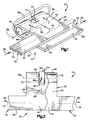
- Fig. 1 is a simplified schematic pictorial illustration of an electrical current sensing apparatus constructed in accordance with the present invention, a magnetic flux sensor being omitted in Fig. 1 for purposes of clarity of illustration;
- Fig. 2 is a top plan view of the electrical current sensing apparatus of Fig. 1 with a magnetic flux sensor positioned relative to the conductor;
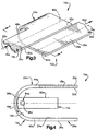
- Fig. 3 is a simplified schematic pictorial illustration of a second embodiment of the electrical current sensing apparatus, a magnetic flux sensor being omitted for purposes of clarity of illustration;
- Fig. 4 is an end view, taken generally along the line 4-4 of Fig. 3 illustrating the relationship of a magnetic flux sensor to the conductor; and
- Fig. 5 is a simplified schematic pictorial illustration, generally similar to Fig. 1, of another embodiment of the electrical current sensing apparatus, a magnetic flux sensor being omitted for purposes of clarity of illustration.
-
- An electrical
current sensing apparatus 10, constructed in accordance with the present invention, is illustrated in Figs. 1 and 2. The electricalcurrent sensing apparatus 10 includes aconductor 12 and a magnetic flux sensor 14 (Fig. 2). Themagnetic flux sensor 14 has been omitted in Fig. 1 in order to illustrate the manner in which magnetic flux is concentrated in an area where the magnetic flux sensor is positioned (Fig. 2). - The
conductor 12 includes longitudinally extendingsections connector section 22. Theconnector section 22 enables themagnetic flux sensor 14 to be positioned at a location where exposure of the magnetic flux sensor to a magnetic flux field emanating from theconductor 12 is maximized. Theconnector section 22 concentrates magnetic flux in an area where theflux sensor 14 is located. - The longitudinally extending
section 18 extends toward the left (as viewed in Figs. 1 and 2) from theconnector section 22. The longitudinally extendingsection 20 extends toward the right from theconnector section 22. Although the longitudinally extendingsections connector section 22, it is contemplated that the longitudinally extendingsections connector section 22 if desired. - The longitudinally extending
sections connector section 22 are integrally formed as one piece of electrically conductive material, that is, a metal such as copper. It is contemplated that the longitudinally extendingsections connector section 22 could be stamped from a single flat piece of sheet metal and then bent to the configuration illustrated in Figs. 1 and 2. Of course, the longitudinally extendingsections connector section 22 of theconductor 12 could be formed in a different manner if desired. It should be understood that the longitudinally extendingsections sections - In the embodiment of the invention illustrated in Figs. 1 and 2, the
magnetic flux sensor 14 is received in anopening 26 formed in theconnector section 22. The illustratedopening 26 is formed as a slot which extends completely through the connector section. The illustratedopening 26 has a rectangular configuration. However, it is contemplated that theopening 26 could have a different configuration if desired. - The left (as viewed in Figs. 1 and 2) longitudinally extending
section 18 of theconductor 12 has flat parallel upper and lowermajor side surfaces section 20 has flat parallel upper and lowermajor side surfaces major side surfaces section 18 of theconductor 12 extend parallel to and are vertically offset from themajor side surfaces section 20. Although themajor side surfaces sections conductor 12 are parallel to each other in the illustrated embodiment of the invention, it is contemplated that the major side surfaces, could, if desired, be skewed relative to each other. - In the embodiment of the invention illustrated in Figs. 1 and 2, the lower
major side surface 32 of the left longitudinally extendingsection 18 extends parallel to and is spaced apart from the uppermajor side surface 34 of the right longitudinally extendingsection 20. However, it is contemplated that themajor side surfaces sections conductor 12 could be positioned in engagement with each other. Alternatively, a layer or thin coating of electrically insulating material could be provided between themajor side surfaces sections conductor 12. - It is also contemplated that the
connector section 22 and the left and right longitudinally extendingsections conductor 12 could be configured so that the uppermajor side surface 30 of the left longitudinally extendingsection 18 is disposed in a coplanar relationship with theupper side surface 34 of the right longitudinally extendingsection 20. Of course, with such a construction, the lowermajor side surfaces sections - The
connector section 22 extends from anend portion 40 of the left longitudinally extendingsection 18 and anend portion 42 of the right longitudinally extendingsection 20. Theconnector section 22 includes a pair ofparallel arm sections arm sections connector section 22 are interconnected by abend section 48. Thebend section 48 concentrates magnetic flux in the space enclosed by the bend section. - In the embodiment of the invention illustrated in Figs. 1 and 2, the arm sections are formed with major side surfaces which are extensions of major side surfaces of the left and right longitudinally extending
sections conductor 12. Thus, the upper (as viewed in Figs. 1 and 2)arm section 44 has an upper major side surface which is an extension of the uppermajor side surface 30 and a lower major side surface which is an extension of the lowermajor side surface 32 of the left longitudinally extendingsection 18. Similarly, thearm section 46 has an upper side surface which is an extension of the uppermajor side surface 34 and a lower major side surface which is an extension of the lowermajor side surface 36 of the right longitudinally extendingsection 20. - The
connector section 22 may be formed separately from the longitudinally extendingsections connector section 22 would be connected to the left longitudinally extendingsection 18. The opposite end of theconnector section 22 would be connected to the right longitudinally extendingsection 20. This construction, would be particularly advantageous if the left and right longitudinally extendingsections - In the illustrated embodiment of the invention, the
arm sections connector section 22 extend parallel to each other. However, it is contemplated that thearm sections parallel arm sections bend section 48 has an arcuate configuration and extends through 180°. Thearm sections bend section 48. However, it is contemplated that thebend section 48 could extend through a greater arcuate distance than 180°. If this was done, theparallel arm sections bend section 48 at additional bends which would extend parallel to thebend section 48. - For example, it is contemplated that the lower major side surface of the
upper arm section 44 and the upper major side section of thelower arm section 46 could be placed in abutting engagement with each other. A thin layer of insulating material could be provided between thearm sections bend section 48 would have an extent of approximately 360°. - Alternatively, the
bend section 48 could be formed with an arcuate extent of less than 180°. Thearm sections bend section 48. If thebend section 48 is formed with a reduced arcuate extent, slight bends could be formed at the junction between thearm sections sections section 18 would be parallel to the major side surfaces 34 and 36 of the right longitudinally extendingsection 20. However, it is believed that it will be preferred to form thebend section 48 with an arcuate extent of at least 180° to promote concentration of magnetic flux inside the bend section. - Electrical current is conducted through the left longitudinally extending
section 18 to theconnector section 22. The flow of electrical current through the left longitudinally extendingsection 18 is indicated schematically by anarrow 52 in Figs. 1 and 2. The electrical current flows from theend portion 40 of the left longitudinally extendingsection 18 into theupper arm section 44 of theconnector section 22 in the manner indicated by anarrow 54 in Fig. 1. The electrical current flows from theupper arm section 44 along opposite sides of theopening 26, in the manner indicated by thearrows - The electrical current then flows around the
bend section 48 and into thelower arm section 46 of theconnector section 22. The electrical current flows from thearm section 46 of theconnector section 22 into theend portion 42 of the right longitudinally extendingsection 20 of theconductor 12. The electrical current then flows through the right longitudinally extendingsection 20 of theconductor 12 in a direction away from theconnector section 22 in the manner indicated byarrows 62 in Figs. 1 and 2. - As the electrical current flows through the
connector section 22, magnetic flux, indicated schematically by dashed lines at 66 in Fig. 1, becomes concentrated in the space disposed on the inside of thebend section 48 of theconnector section 22. The magnetic flux is concentrated by reducing the radius of theconnector section 22. - To further promote the concentration of magnetic flux at the inside of the
bend section 48, a pair ofmagnetic members bend section 48. In the illustrated embodiment of the invention, themagnetic members bend section 48 is the same as the radius of curvature of the cylindrical outer side surfaces of themagnetic members magnetic members - The left and right longitudinally extending
sections conductor 12 have parallelcentral axes central axes sections central axis 82 of theconnector section 22 extends parallel to thecentral axes longitudinally extending sections - The
central axis 82 of theconnector section 22 extends through the center of curvature of thebend section 48 and through themagnetic members - The
opening 26 has acentral axis 86 which extends around thebend section 48 and extends perpendicular to and intersects thecentral axes sections central axis 86 of theopening 26 has parallel linear segments which are interconnected by an arcuate bend segment. The bend segment of thecentral axis 86 of theopening 26 has a center of curvature disposed on theaxis 82. - Although it is contemplated that the electrical
current sensing apparatus 10 could be constructed in many different ways, in the illustrated embodiment of the invention, the electrical current sensing apparatus is constructed by stamping thelongitudinally extending sections connector section 22 from a flat sheet of material and subsequently forming the connector section in a reverse bend to the shape illustrated in the drawings. - Although it is contemplated that it may be preferred to form the electrical
current sensing apparatus 10 in this manner, it should be understood that the electrical current sensing apparatus could be formed in a different manner if desired. For example, thebend section 48 could have a rectangular configuration rather than an arcuate configuration. If this is done, themagnetic members - Although it is preferred to use the
magnetic members flux 66 at thebend section 48, themagnetic members magnetic members bend section 48 would, itself, promote the concentration of theflux 66 emanating from the electrical current conducted through theconnector section 22. Thebend section 48 causes the magnetic flux to become concentrated on the inside of the bend section. The concentration of flux is inversely proportional to the radius of the bend section. An optimum radius is one-half the dimension of the flux sensitive area of the Hall effect device, and the concentration occurs on theaxis 82. - The flux sensitive area of the
flux sensor 14 andbend section 48 may have many different dimensions. In one specific instance, the flux sensitive area of theflux sensor 14 has a diameter of 0.060 inches and thebend section 48 had an inside radius of approximately 0.030 inches. However, it is contemplated that theflux sensor 14 could have a diameter of 0.005 inches and thebend section 48 could have an inside radius of 0.0025 inches. Of course, if the flux sensitive area of theflux sensor 14 is larger, thebend section 48 would have a larger radius. - The
magnetic flux sensor 14 is advantageously positioned in the opening 26 (Fig. 2). Themagnetic flux sensor 14 includes asupport structure 92 formed of an electrically insulating material. A magnetic fluxresponsive device 94 is held by thesupport structure 92 in the manner indicated schematically in Fig. 2. In the illustrated embodiment of the invention, the magnetic fluxresponsive device 94 is a Hall effect device. However, other known magnetic flux responsive devices could be utilized if desired. - The
support structure 92 positions theHall effect device 94 between circular end surfaces on themagnetic members central axes 82 of thebend section 48 and themagnetic members Hall effect device 94. A fluxsensitive side surface 96 on theHall effect device 94 extends perpendicular to and is intersected by thecentral axis 82 of thebend section 48. - It should be understood that the
Hall effect device 94 could be supported in theopening 26 in a different manner if desired. For example, theHall effect device 94 could be supported by either or both of themagnetic members Hall effect device 94 could be supported by engagement of a support bracket with theconnector section 22. - The
Hall effect device 94 is connected with suitable control circuitry (not shown). The output from theHall effect device 94 varies as a function of variations in the strength of themagnetic flux 66 conducted through theHall effect device 94. Of course, the strength of themagnetic flux 66 conducted through theHall effect device 94 will vary as a function of the flow of current through theconductor 12. Therefore, the output from theHall effect device 94 will vary as a function of variations in the current conducted through theconductor 12. This enables the control circuitry connected with theHall effect device 94 to initiate a suitable control function in the event of variations in the rate of flow of current through theconductor 12. - In the embodiment of the invention illustrated in Figs. 1 and 2, an
opening 26 is provided in theconnector section 22 to receive the magnetic flux sensor 14 (Fig. 2). In the embodiment of the invention illustrated in Figs. 3 and 4, the connector section is free of openings. Since the embodiment of the invention illustrated in Figs. 3 and 4 has the same general construction as the embodiment of the invention illustrated in Figs. 1 and 2, similar numerals will be utilized to designate similar components, the suffix letter "a" being associated with the numerals of Figs. 3 and 4 to avoid confusion. - An electrical
current sensing apparatus 10a (Figs. 3 and 4) includes aconductor 12a. Theconductor 12a includes longitudinally extendingsections connector section 22a extends between the left and right longitudinally extendingsections connector section 22a is integrally formed as one piece with thelongitudinally extending sections connector section 22a and longitudinally extendingsections - The left longitudinally extending
section 18a includes flat parallel upper and lowermajor side surfaces section 20a includes flat parallel upper and lowermajor side surfaces major side surfaces section 20a extend parallel to themajor side surfaces section 18a.End portions sections connector section 22a. - The
connector section 22a includes upper andlower arm sections 44a and 46a (Fig. 4) which are connected with abend section 48a. Electrical current, indicated schematically at 52a in Fig. 3, is conducted through the left longitudinally extendingsection 18a to theconnector section 22a. The electrical current flows through thebend section 48a of theconnector section 22a, in the manner indicated schematically by anarrow 56a in Fig. 4. The electrical current flows away from theconnector section 22a through the right longitudinally extendingsection 20a in the manner indicated by anarrow 62a in Fig. 3. - The left and right longitudinally extending
sections central axes axes major side surfaces sections central axis 82a of theconnector section 22a extends parallel to and is spaced equal distances from thecentral axes longitudinally extending sections conductor 12a. Theaxis 82a extends through the center of curvature of thebend section 48a. - In the embodiment of the invention illustrated in Figs. 3 and 4, a
magnetic flux sensor 14a is disposed within theconnector section 22a and between the left and right longitudinally extendingsections conductor 12a (Fig. 4). Themagnetic flux sensor 14a includes asupport structure 92a and a magnetic fluxresponsive device 94a. In the specific embodiment of the invention illustrated in Fig. 4, the magnetic flux responsive device is aHall effect device 94a. TheHall effect device 94a is supported by thesupport structure 92a with a flux sensitive side surface 96a of theHall effect device 94a extending perpendicular to thecentral axis 82a (Fig. 3) of theconnector section 22a and perpendicular to thecentral axes longitudinally extending sections - In the embodiment of the invention illustrated in Fig. 4, the
Hall effect device 94a is offset, toward the left (as viewed in Fig. 4) of the center of curvature of thebend section 48a. However, if desired, thesupport structure 92a could position theHall effect device 94a so that thecentral axis 82a of thebend section 22a extends through the center of the Hall effect device 96a. In the embodiment of the invention illustrated in Fig. 4, thesupport structure 92a engages aninner side surface 104 of thearcuate bend section 48a to position themagnetic flux sensor 14a relative to theconductor 12a. However, If desired, the support structure could be spaced from thebend section 48a. - When the electrical current 56a flows around the
bend section 48a, in the manner indicated schematically in Fig. 4, magnetic flux is concentrated in the area around the inside of thebend section 48a. By positioning theHall effect device 94a inside thebend section 48a of theconductor 12a, the Hall effect device is positioned in the concentrated magnetic flux resulting from the electrical current 56a. - The
Hall effect device 94a is connected with suitable control circuitry. Upon a variation in the electrical current 56a flowing through theconductor 12a, there is a corresponding variation in the output of theHall effect device 94a. The control circuitry may initiate a suitable control function in response to a variation in the output from theHall effect device 94a. - In the embodiment of the invention illustrated in Figs. 1 and 2,
magnetic members bend section 48. In the embodiment of the invention illustrated in Fig. 5, the magnetic members are formed as one piece and extend around the outside of the bend section. Since the embodiment of the invention illustrated in Fig. 5 is generally similar to the embodiment of the invention illustrated in Figs. 1 and 2, similar numerals will be utilized to designate similar components, the suffix letter "b" being associated with the numerals of Fig. 5 to avoid confusion. - An electrical
current sensing apparatus 10b (Fig. 5) includes a conductor 12b. The conductor 12b includes longitudinally extendingsections 18b and 20b. Aconnector section 22b extends between the left and right longitudinally extendingsections 18b and 20b. Theconnector section 22b is integrally formed as one piece with thelongitudinally extending sections 18b and 20b. However, theconnector section 22b and longitudinally extendingsections 18b and 20b could be formed separately and then interconnected. - The left longitudinally extending
section 18b includes flat parallel upper major and lower side surfaces 30b and 32b. The right longitudinally extending section 20b includes flat parallel upper major and lower side surfaces 34b and 36b. The upper and lower major side surfaces 34b and 36b of the right longitudinally extending section 20b extend parallel to the major side surfaces 30b and 32b of the left longitudinally extendingsection 18b.End portions sections 18b and 20b are connected with theconnector section 22b. Upper andlower arm sections bend section 48b. - Electrical current, indicated schematically at 52b in Fig. 5, is conducted through the left longitudinally extending
section 18b and flows through thebend section 48b of theconnector section 22b, in a manner indicated schematically byarrows connector section 22b through the right longitudinally extending section 20b in the manner indicated by an arrow 62b in Fig. 3. - The left and right longitudinally extending
sections 18b and 20b have parallelcentral axes axes major side surfaces sections 18b and 20b. Acentral axis 82b of theconnector section 22b extends parallel to and is spaced equal distances from thecentral axes longitudinally extending sections 18b and 20b of the conductor 12b. Theaxis 82b extends through the center of curvature of the bend section 38b. - In accordance with the embodiment of the invention illustrated in Fig. 5, to promote the concentration of magnetic flux at the inside of the
bend section 48b, a one-piece magnetic member 110 (Fig. 5) is positioned in thebend section 48b and extends around the outside of the bend section. Themagnetic member 110 concentrates magnetic flux emanating from the current flowing through theconnector section 22b. Thus, magnetic flux is concentrated between circular end surfaces 112 and 114 on themagnetic member 110. The end surfaces 112 and 114 have centers which are disposed on thecentral axis 82b of theconnector section 22b. - The one-piece
magnetic member 110 hasend sections opening 26b is formed in theconnector section 22b and extends completely through the connector section. The end surfaces 112 and 114 on theend sections magnetic member 110 are aligned with opposite sides of theopening 26b. - A magnetic flux sensor, corresponding to the
magnetic flux sensor 14 of Fig. 2, may be positioned in theopening 26b in the same manner as previously explained in conjunction with the embodiment of the invention illustrated in Figs. 1 and 2. The magnetic flux sensor would have the same construction as themagnetic flux sensor 14 of Fig. 2 and would include a magnetic flux responsive device, such as a Hall effect device, which is supported by a support structure, corresponding to thesupport structure 92 of Fig. 2. It should be understood that other known magnetic flux responsive devices could be utilized if desired. - The one-piece
magnetic member 110 includes acylindrical connector section 124 which is connected with theend sections arcuate bend sections connector section 124 has acentral axis 132 which extends parallel to thecentral axis 82b of theconnector section 22b. Theaxes major side surfaces sections 18b and 20b of the conductor 12b. - The one-piece
magnetic member 110 concentrates magnetic flux at theopening 26b in theconnector section 22b. The magnetic flux sensor (not shown in Fig. 5 but similar to themagnetic flux sensor 14 in Fig. 2), includes a magnetic flux responsive device which is positioned on theaxis 82b. Thebend section 48b cooperates with theend sections magnetic member 110 to concentrate magnetic flux at theopening 26b where the magnetic flux sensor is located. Theconnector section 124 of the one-piecemagnetic member 110 promotes the flow of magnetic flux between theend sections - In view of the foregoing description, it is apparent that the present invention provides an electrical current sensing apparatus 10 (Figs. 1-4) which includes an electrical
current conductor 12 having aconnector section 22 which extends between longitudinally extendingsections magnetic flux sensor 14 is disposed adjacent to theconnector section 22. Themagnetic flux sensor 14 may include asupport 92 formed of electrically insulating material and a magnetic flux responsive device, such as aHall effect device 94. - The
connector section 22 may have acentral axis 82 which extends parallel tocentral axes longitudinally extending sections conductor 12. TheHall effect device 94 may have a fluxsensitive surface 96 which extends perpendicular to thecentral axis 82 of theconnector section 22. In one embodiment of the invention, themagnetic flux sensor 14 is at least partially disposed in anopening 26 formed in theconnector section 22 of the conductor. In another embodiment of the invention, themagnetic flux sensor 14 is disposed in engagement with aninner surface 104 of the connector section.
Claims (19)
- An electrical current sensing apparatus (10) comprising an electrical current conductor (12) having first and second longitudinally extending sections (18, 20) and a connector section (22) extending between said first and second longitudinally extending sections, said connector section (22) having a central axis (82), and a magnetic flux sensor (14) disposed adjacent to said central axis (82) of said connector section to detect variations in current conducted through said conductor.
- An apparatus as set forth in claim 1 wherein said connector section (22) at least partially defines an opening (26), said magnetic flux sensor (14) being at least partially disposed in said opening.
- An apparatus as set forth in claim 1 wherein at least a portion (48) of said connector section (22) has an arcuate cross sectional configuration, said magnetic flux sensor (14) includes a support (92) and a Hall effect device (94) disposed on said support, said Hall effect device (94) being disposed between parallel planes extending from opposite end portions of an inner side surface of said connector section.
- An apparatus as set forth in claim 3 wherein the central axis (82) of said connector section (22) extends through said Hall effect device (94).
- An apparatus as set forth in claim 3 wherein said Hall effect device (94) has a flux sensitive side surface (96) which extends perpendicular to the central axis (82) of said connector section (22).
- An apparatus as set forth in claim 1 further including a magnetic member (70) at least partially enclosed by said connector section (22) and disposed adjacent to said magnetic flux sensor.
- An apparatus as set forth in claim 6 wherein said central axis (82) of said connector section (22) is coincident with a central axis of said magnetic member (70).
- An apparatus as set forth in claim 1 further including a magnetic member (110) having first and second end sections (116, 118) which are at least partially enclosed by said connector section (22b) of said conductor (12b) and an intermediate section (124) which is disposed outside of said connector section of said conductor.
- An apparatus as set forth in claim 1 wherein said first and second longitudinally extending sections (18, 20) have spaced apart major side surfaces (32, 34).
- An apparatus as set forth in claim 1 wherein said electrical current (52) flows through said first longitudinally extending section (18) to said connector section (22) and flows from said connector section through said second longitudinally extending section (20).
- An apparatus as set forth in claim 1 wherein the first longitudinally extending section (18) is offset from the second longitudinally extending section (20).
- An apparatus as set forth in claim 1 wherein said connector section(22) has a bend portion (48) with an arcuate configuration and an extent of at least 180 degrees.
- An apparatus as set forth in claim 1 wherein said first and second longitudinally extending sections (18, 20) extend in opposite directions from said connector section.
- An apparatus as set forth in claim 1 wherein said magnetic flux sensor (14) is disposed in fixed proximity with an arcuate inner side surface of said connector section (22).
- An apparatus as set forth in claim 1 wherein said connector section (22a) includes a continuously curving outer side surface area (48a) which is free of openings.
- An apparatus as set forth in claim 1 wherein said magnetic flux sensor (14) extends through a slot (26) in an outer side surface of said connector section (22), said magnetic flux sensor (14) includes a support (92) which is at least partially formed of an electrically insulating material and is at least partially disposed in the slot (26) in said connector section (22) and a Hall effect device (94) which is supported by said support (92) and has a flux sensitive side surface (96) which extends perpendicular to a central axis (82) of said connector section (22).
- An apparatus as set forth in claim 16 further including first and second members (70, 72) formed of an electrically conductive material and at least partially enclosed by said connector section (22), said Hall effect device (14) being disposed between an end portion of said first member (70) and an end portion of said second member (72).
- An apparatus as set forth in claim 17 wherein said first and second members (70, 72) have central axes which extend through said Hall effect device (14).
- An apparatus as set forth in claim 16 further including a magnetic member (110) having first and second end sections (116, 118) which are at least partially enclosed by said connector section (22) of said conductor and an intermediate section (124) which is disposed outside of said connector section (22) and extends across the slot (26b) in said connector section.
Applications Claiming Priority (2)
| Application Number | Priority Date | Filing Date | Title |
|---|---|---|---|
| US368051 | 1999-08-03 | ||
| US09/368,051 US6130599A (en) | 1999-08-03 | 1999-08-03 | Electrical current sensing apparatus |
Publications (2)
| Publication Number | Publication Date |
|---|---|
| EP1074847A1 true EP1074847A1 (en) | 2001-02-07 |
| EP1074847B1 EP1074847B1 (en) | 2006-09-27 |
Family
ID=23449682
Family Applications (1)
| Application Number | Title | Priority Date | Filing Date |
|---|---|---|---|
| EP00116810A Expired - Lifetime EP1074847B1 (en) | 1999-08-03 | 2000-08-03 | Electrical current sensing apparatus |
Country Status (6)
| Country | Link |
|---|---|
| US (1) | US6130599A (en) |
| EP (1) | EP1074847B1 (en) |
| JP (1) | JP2001099873A (en) |
| CN (1) | CN1181350C (en) |
| BR (1) | BR0003531A (en) |
| DE (1) | DE60030918T2 (en) |
Cited By (1)
| Publication number | Priority date | Publication date | Assignee | Title |
|---|---|---|---|---|
| WO2015088661A1 (en) * | 2013-12-11 | 2015-06-18 | Eaton Corporation | Current sensing assembly employing magnetic sensors |
Families Citing this family (18)
| Publication number | Priority date | Publication date | Assignee | Title |
|---|---|---|---|---|
| US6271744B1 (en) * | 2000-03-03 | 2001-08-07 | Trw Inc. | Current sensing arrangement with encircling current-carrying line and ferromagnetic sheet concentrator |
| WO2005033716A1 (en) * | 2003-10-01 | 2005-04-14 | Eaton Corporation | System and method for current sensing using anti-differential, error correcting current sensing |
| US7253602B2 (en) * | 2004-10-12 | 2007-08-07 | Eaton Corporation | Self-powered power bus sensor employing wireless communication |
| US7145322B2 (en) * | 2004-10-12 | 2006-12-05 | Eaton Corporation | Self-powered power bus sensor employing wireless communication |
| US7667482B2 (en) * | 2007-09-21 | 2010-02-23 | Eaton Corporation | Inductively powered power bus apparatus |
| US8831787B2 (en) * | 2007-11-26 | 2014-09-09 | Safeworks, Llc | Power sensor |
| JP5366418B2 (en) * | 2008-03-24 | 2013-12-11 | 東光東芝メーターシステムズ株式会社 | Current detector and watt-hour meter using the same |
| JP5820164B2 (en) * | 2011-07-01 | 2015-11-24 | 東光東芝メーターシステムズ株式会社 | Current detection device and watt-hour meter using the same |
| US9093867B2 (en) | 2011-09-23 | 2015-07-28 | Eaton Corporation | Power system including an electret for a power bus |
| US8791831B2 (en) | 2011-09-23 | 2014-07-29 | Eaton Corporation | System including an indicator responsive to an electret for a power bus |
| US9651581B2 (en) * | 2011-09-28 | 2017-05-16 | Infineon Technologies Ag | High current sensors |
| EP2766222B1 (en) * | 2011-10-12 | 2022-06-08 | Cequent Performance Products, Inc. | Current sensing electrical converter |
| JP5873315B2 (en) * | 2011-12-13 | 2016-03-01 | 矢崎総業株式会社 | Shunt resistance type current sensor |
| JP6372969B2 (en) * | 2012-12-03 | 2018-08-15 | 矢崎総業株式会社 | Current sensor |
| US9746500B2 (en) | 2013-12-11 | 2017-08-29 | Eaton Corporation | Electrical current sensing apparatus |
| US9134351B2 (en) | 2013-12-11 | 2015-09-15 | Eaton Corporation | Bi-directional direct current sensing circuit and current sensing assembly including the same |
| US9651587B2 (en) | 2014-04-25 | 2017-05-16 | Eaton Corporation | Apparatus including electrodes, a rectifier or circuit, and an illuminated or non-illuminated indicator for visual indication of energized electrical conductors |
| JP6890112B2 (en) * | 2018-11-15 | 2021-06-18 | 矢崎総業株式会社 | Current detector |
Citations (2)
| Publication number | Priority date | Publication date | Assignee | Title |
|---|---|---|---|---|
| US4559495A (en) * | 1981-03-26 | 1985-12-17 | Lgz Landis & Gyr Zug Ag | Transducer free of any magnetic core for contactless current measurement |
| US5642041A (en) * | 1994-11-21 | 1997-06-24 | General Electric Company | Alternating current sensor employing parallel plates and having high dynamic range and accuracy |
Family Cites Families (13)
| Publication number | Priority date | Publication date | Assignee | Title |
|---|---|---|---|---|
| US3234461A (en) * | 1960-12-05 | 1966-02-08 | Texas Instruments Inc | Resistivity-measuring device including solid inductive sensor |
| US3335383A (en) * | 1965-01-04 | 1967-08-08 | Gen Telephone & Elect | Hall-effect multiplier |
| GB2000873B (en) * | 1977-07-08 | 1982-05-26 | Landis & Gyr Ag | Measuring transformers for potential-free measurement of currents or voltages and static electricity meters including such transformers |
| US4182982A (en) * | 1978-07-11 | 1980-01-08 | Westinghouse Electric Corp. | Current sensing transducer for power line current measurements |
| CH658929A5 (en) * | 1982-10-28 | 1986-12-15 | Landis & Gyr Ag | POWER DIVIDER FOR MEASURING TRANSDUCERS. |
| CH660538A5 (en) * | 1983-03-02 | 1987-04-30 | Landis & Gyr Ag | MEASURING CONVERTER FOR MEASURING A CURRENT. |
| CH658930A5 (en) * | 1983-04-25 | 1986-12-15 | Landis & Gyr Ag | CURRENT DIVIDER FOR MEASURING TRANSDUCERS FOR MEASURING A CURRENT. |
| GB2143038B (en) * | 1983-07-06 | 1987-12-23 | Standard Telephones Cables Ltd | Hall effect device |
| US4616207A (en) * | 1984-10-12 | 1986-10-07 | Gould Inc. | Electric fuse holder having a Hall-effect current sensor |
| US4749940A (en) * | 1986-12-22 | 1988-06-07 | General Electric Company | Folded bar current sensor |
| US5027059A (en) * | 1989-08-24 | 1991-06-25 | Schlumberger Industries, Inc. | Differential current shunt |
| US5587652A (en) * | 1994-11-21 | 1996-12-24 | General Electric Company | Alternating current sensor based on parallel-plate geometry and having a shunt for self-powering |
| US5917401A (en) * | 1997-02-26 | 1999-06-29 | Sundstrand Corporation | Conductive bus member and method of fabricating same |
-
1999
- 1999-08-03 US US09/368,051 patent/US6130599A/en not_active Expired - Fee Related
-
2000
- 2000-07-31 JP JP2000231889A patent/JP2001099873A/en not_active Withdrawn
- 2000-08-02 BR BR0003531-9A patent/BR0003531A/en not_active IP Right Cessation
- 2000-08-03 CN CNB001225162A patent/CN1181350C/en not_active Expired - Fee Related
- 2000-08-03 DE DE60030918T patent/DE60030918T2/en not_active Expired - Fee Related
- 2000-08-03 EP EP00116810A patent/EP1074847B1/en not_active Expired - Lifetime
Patent Citations (2)
| Publication number | Priority date | Publication date | Assignee | Title |
|---|---|---|---|---|
| US4559495A (en) * | 1981-03-26 | 1985-12-17 | Lgz Landis & Gyr Zug Ag | Transducer free of any magnetic core for contactless current measurement |
| US5642041A (en) * | 1994-11-21 | 1997-06-24 | General Electric Company | Alternating current sensor employing parallel plates and having high dynamic range and accuracy |
Cited By (3)
| Publication number | Priority date | Publication date | Assignee | Title |
|---|---|---|---|---|
| WO2015088661A1 (en) * | 2013-12-11 | 2015-06-18 | Eaton Corporation | Current sensing assembly employing magnetic sensors |
| US9846180B2 (en) | 2013-12-11 | 2017-12-19 | Eaton Corporation | Current sensing assembly employing magnetic sensors |
| US10191089B2 (en) | 2013-12-11 | 2019-01-29 | Eaton Intelligent Power Limited | Current sensing assembly employing magnetic sensors |
Also Published As
| Publication number | Publication date |
|---|---|
| DE60030918T2 (en) | 2007-06-06 |
| CN1284654A (en) | 2001-02-21 |
| EP1074847B1 (en) | 2006-09-27 |
| BR0003531A (en) | 2001-03-13 |
| JP2001099873A (en) | 2001-04-13 |
| DE60030918D1 (en) | 2006-11-09 |
| CN1181350C (en) | 2004-12-22 |
| US6130599A (en) | 2000-10-10 |
Similar Documents
| Publication | Publication Date | Title |
|---|---|---|
| US6130599A (en) | Electrical current sensing apparatus | |
| US6271656B1 (en) | Electrical current sensing apparatus | |
| EP1037057A2 (en) | Electrical current sensing apparatus | |
| EP2083277B1 (en) | Electrical current sensor | |
| CN1083982C (en) | Electrical current sensor | |
| EP1467214A3 (en) | Current sensor and current detection unit using the same | |
| EP3918347B1 (en) | Current transducer with magnetic field detector module | |
| EP2843424B1 (en) | Current transducer for measuring an electrical current flowing through a cable | |
| US11639879B2 (en) | Linear force sensor and method of use | |
| EP4346017A1 (en) | Connector | |
| EP0367442B1 (en) | Torque sensing device | |
| US20020050068A1 (en) | Inclination sensor | |
| US6803759B2 (en) | Passive magnetic position sensor | |
| US6441610B2 (en) | Robotic gripper having proximity sensor with off-set sensor | |
| EP1817552B1 (en) | Co-located sensing elements for quadrature sensor | |
| KR102723420B1 (en) | Current detection device | |
| CA2291406A1 (en) | Magnetic field sensor and system for measuring a magnetic field | |
| JPH0338754Y2 (en) | ||
| JP2022014161A (en) | Current sensor | |
| US5093615A (en) | Movement for an instrument having an electromagnetic control arrangement | |
| US11680956B2 (en) | Rotation detection device | |
| JPH0351707Y2 (en) | ||
| JPH0511893Y2 (en) | ||
| JP2596926Y2 (en) | Electromagnetic flow meter | |
| JPH0132669Y2 (en) |
Legal Events
| Date | Code | Title | Description |
|---|---|---|---|
| PUAI | Public reference made under article 153(3) epc to a published international application that has entered the european phase |
Free format text: ORIGINAL CODE: 0009012 |
|
| AK | Designated contracting states |
Kind code of ref document: A1 Designated state(s): AT BE CH CY DE DK ES FI FR GB GR IE IT LI LU MC NL PT SE |
|
| AX | Request for extension of the european patent |
Free format text: AL;LT;LV;MK;RO;SI |
|
| 17P | Request for examination filed |
Effective date: 20010713 |
|
| AKX | Designation fees paid |
Free format text: DE FR GB |
|
| 17Q | First examination report despatched |
Effective date: 20041109 |
|
| GRAC | Information related to communication of intention to grant a patent modified |
Free format text: ORIGINAL CODE: EPIDOSCIGR1 |
|
| GRAP | Despatch of communication of intention to grant a patent |
Free format text: ORIGINAL CODE: EPIDOSNIGR1 |
|
| RTI1 | Title (correction) |
Free format text: ELECTRICAL CURRENT SENSING APPARATUS |
|
| RTI1 | Title (correction) |
Free format text: ELECTRICAL CURRENT SENSING APPARATUS |
|
| GRAS | Grant fee paid |
Free format text: ORIGINAL CODE: EPIDOSNIGR3 |
|
| GRAA | (expected) grant |
Free format text: ORIGINAL CODE: 0009210 |
|
| AK | Designated contracting states |
Kind code of ref document: B1 Designated state(s): DE FR GB |
|
| REG | Reference to a national code |
Ref country code: GB Ref legal event code: FG4D |
|
| REF | Corresponds to: |
Ref document number: 60030918 Country of ref document: DE Date of ref document: 20061109 Kind code of ref document: P |
|
| ET | Fr: translation filed | ||
| PLBE | No opposition filed within time limit |
Free format text: ORIGINAL CODE: 0009261 |
|
| STAA | Information on the status of an ep patent application or granted ep patent |
Free format text: STATUS: NO OPPOSITION FILED WITHIN TIME LIMIT |
|
| PGFP | Annual fee paid to national office [announced via postgrant information from national office to epo] |
Ref country code: DE Payment date: 20070831 Year of fee payment: 8 |
|
| 26N | No opposition filed |
Effective date: 20070628 |
|
| PGFP | Annual fee paid to national office [announced via postgrant information from national office to epo] |
Ref country code: GB Payment date: 20070705 Year of fee payment: 8 |
|
| PGFP | Annual fee paid to national office [announced via postgrant information from national office to epo] |
Ref country code: FR Payment date: 20070803 Year of fee payment: 8 |
|
| GBPC | Gb: european patent ceased through non-payment of renewal fee |
Effective date: 20080803 |
|
| REG | Reference to a national code |
Ref country code: FR Ref legal event code: ST Effective date: 20090430 |
|
| PG25 | Lapsed in a contracting state [announced via postgrant information from national office to epo] |
Ref country code: FR Free format text: LAPSE BECAUSE OF NON-PAYMENT OF DUE FEES Effective date: 20080901 Ref country code: DE Free format text: LAPSE BECAUSE OF NON-PAYMENT OF DUE FEES Effective date: 20090303 |
|
| PG25 | Lapsed in a contracting state [announced via postgrant information from national office to epo] |
Ref country code: GB Free format text: LAPSE BECAUSE OF NON-PAYMENT OF DUE FEES Effective date: 20080803 |