EP1074730A2 - Center feed of air for assist fuel injector - Google Patents
Center feed of air for assist fuel injector Download PDFInfo
- Publication number
- EP1074730A2 EP1074730A2 EP00202772A EP00202772A EP1074730A2 EP 1074730 A2 EP1074730 A2 EP 1074730A2 EP 00202772 A EP00202772 A EP 00202772A EP 00202772 A EP00202772 A EP 00202772A EP 1074730 A2 EP1074730 A2 EP 1074730A2
- Authority
- EP
- European Patent Office
- Prior art keywords
- air
- assist
- fuel injector
- passageway
- injector pockets
- Prior art date
- Legal status (The legal status is an assumption and is not a legal conclusion. Google has not performed a legal analysis and makes no representation as to the accuracy of the status listed.)
- Granted
Links
Images



Classifications
-
- F—MECHANICAL ENGINEERING; LIGHTING; HEATING; WEAPONS; BLASTING
- F02—COMBUSTION ENGINES; HOT-GAS OR COMBUSTION-PRODUCT ENGINE PLANTS
- F02M—SUPPLYING COMBUSTION ENGINES IN GENERAL WITH COMBUSTIBLE MIXTURES OR CONSTITUENTS THEREOF
- F02M35/00—Combustion-air cleaners, air intakes, intake silencers, or induction systems specially adapted for, or arranged on, internal-combustion engines
- F02M35/10—Air intakes; Induction systems
- F02M35/10209—Fluid connections to the air intake system; their arrangement of pipes, valves or the like
- F02M35/10222—Exhaust gas recirculation [EGR]; Positive crankcase ventilation [PCV]; Additional air admission, lubricant or fuel vapour admission
-
- F—MECHANICAL ENGINEERING; LIGHTING; HEATING; WEAPONS; BLASTING
- F02—COMBUSTION ENGINES; HOT-GAS OR COMBUSTION-PRODUCT ENGINE PLANTS
- F02M—SUPPLYING COMBUSTION ENGINES IN GENERAL WITH COMBUSTIBLE MIXTURES OR CONSTITUENTS THEREOF
- F02M35/00—Combustion-air cleaners, air intakes, intake silencers, or induction systems specially adapted for, or arranged on, internal-combustion engines
- F02M35/10—Air intakes; Induction systems
- F02M35/10006—Air intakes; Induction systems characterised by the position of elements of the air intake system in direction of the air intake flow, i.e. between ambient air inlet and supply to the combustion chamber
- F02M35/10026—Plenum chambers
- F02M35/10039—Intake ducts situated partly within or on the plenum chamber housing
-
- F—MECHANICAL ENGINEERING; LIGHTING; HEATING; WEAPONS; BLASTING
- F02—COMBUSTION ENGINES; HOT-GAS OR COMBUSTION-PRODUCT ENGINE PLANTS
- F02M—SUPPLYING COMBUSTION ENGINES IN GENERAL WITH COMBUSTIBLE MIXTURES OR CONSTITUENTS THEREOF
- F02M35/00—Combustion-air cleaners, air intakes, intake silencers, or induction systems specially adapted for, or arranged on, internal-combustion engines
- F02M35/10—Air intakes; Induction systems
- F02M35/10209—Fluid connections to the air intake system; their arrangement of pipes, valves or the like
- F02M35/10216—Fuel injectors; Fuel pipes or rails; Fuel pumps or pressure regulators
-
- F—MECHANICAL ENGINEERING; LIGHTING; HEATING; WEAPONS; BLASTING
- F02—COMBUSTION ENGINES; HOT-GAS OR COMBUSTION-PRODUCT ENGINE PLANTS
- F02M—SUPPLYING COMBUSTION ENGINES IN GENERAL WITH COMBUSTIBLE MIXTURES OR CONSTITUENTS THEREOF
- F02M35/00—Combustion-air cleaners, air intakes, intake silencers, or induction systems specially adapted for, or arranged on, internal-combustion engines
- F02M35/10—Air intakes; Induction systems
- F02M35/104—Intake manifolds
-
- F—MECHANICAL ENGINEERING; LIGHTING; HEATING; WEAPONS; BLASTING
- F02—COMBUSTION ENGINES; HOT-GAS OR COMBUSTION-PRODUCT ENGINE PLANTS
- F02M—SUPPLYING COMBUSTION ENGINES IN GENERAL WITH COMBUSTIBLE MIXTURES OR CONSTITUENTS THEREOF
- F02M69/00—Low-pressure fuel-injection apparatus ; Apparatus with both continuous and intermittent injection; Apparatus injecting different types of fuel
- F02M69/04—Injectors peculiar thereto
- F02M69/047—Injectors peculiar thereto injectors with air chambers, e.g. communicating with atmosphere for aerating the nozzles
-
- F—MECHANICAL ENGINEERING; LIGHTING; HEATING; WEAPONS; BLASTING
- F02—COMBUSTION ENGINES; HOT-GAS OR COMBUSTION-PRODUCT ENGINE PLANTS
- F02M—SUPPLYING COMBUSTION ENGINES IN GENERAL WITH COMBUSTIBLE MIXTURES OR CONSTITUENTS THEREOF
- F02M69/00—Low-pressure fuel-injection apparatus ; Apparatus with both continuous and intermittent injection; Apparatus injecting different types of fuel
- F02M69/08—Low-pressure fuel-injection apparatus ; Apparatus with both continuous and intermittent injection; Apparatus injecting different types of fuel characterised by the fuel being carried by compressed air into main stream of combustion-air
-
- F—MECHANICAL ENGINEERING; LIGHTING; HEATING; WEAPONS; BLASTING
- F02—COMBUSTION ENGINES; HOT-GAS OR COMBUSTION-PRODUCT ENGINE PLANTS
- F02M—SUPPLYING COMBUSTION ENGINES IN GENERAL WITH COMBUSTIBLE MIXTURES OR CONSTITUENTS THEREOF
- F02M69/00—Low-pressure fuel-injection apparatus ; Apparatus with both continuous and intermittent injection; Apparatus injecting different types of fuel
- F02M69/46—Details, component parts or accessories not provided for in, or of interest apart from, the apparatus covered by groups F02M69/02 - F02M69/44
Definitions
- This application is an application for patent that relates to air intake systems for internal combustion engines, particularly internal combustion engines for automobiles. More particularly, it relates to intake manifolds and air assist rails and methods for making the same.
- Fuel injectors are often designed to use air under pressure to assist the atomization of fuel by the injectors. Since each injector in an engine requires air assist, each injector is connected to a supply of pressurized air.
- the air is supplied to a bank of injectors by an external pod or rail.
- This pod is rigid and is attached to a row of injectors along a single bank.
- two pods are provided where each pod is connected to the injectors for a single bank of cylinders.
- the air assist passageway is not provided by an external pod, but is formed as a passageway internal to the intake manifold.
- the external pod requires additional piping and connections for each of the injectors, it also permits a passageway with optimum air pressure and air distribution. It also permits the intake manifold and cylinder head geometry to be kept simple.
- Air assist passageways formed internal to the manifold are significantly constrained in their design. For example, they are either molded using pins, or are formed by gun drilling the manifold after it is molded. As a result, the air assist passageways typically have a circular cross section with a relatively constant cross section area, and a straight longitudinal axis. Their diameter is typically limited to fit between and around the injector pockets and the air induction ports for each cylinder. The longitudinal axes of the air assist passageways formed in the manifold are typically offset to one side of the fuel injector pockets such that they intersect the air injector pockets on one side.
- the air assist passageways on a V-8 engine would be fed from an air line connected to an end of the air assist passageway.
- the passageway would have to pass three fuel injectors, all of them introducing pressure pulsations into the system that would affect the end cylinder.
- the air assist passageway would pass five fuel injectors before reaching the last fuel injector in the bank of cylinders. Five fuel injectors introduce their pressure pulsations into the air assist passageway that would affect the last fuel injector.
- an air intake system for an internal combustion engine having at least one bank of cylinders adjacent to each other including a first plurality of air induction passageways couplable to the at least one bank of cylinders for conducting combustion air to the cylinders in the first bank of cylinders, a first plurality of fuel injector pockets, each fluidly coupled with one of the first plurality of air induction passageways, and a first air assist passageway fluidly coupled with the first plurality of fuel injector pockets to communicate assist air to each of the fuel injector pockets, wherein the first air assist passageway has a first assist air feed port for receiving assist air and the first assist air port is disposed between at least two of the first plurality of fuel injector pockets.
- the air intake system may also include a second plurality of air induction passageways couplable to at least another bank of cylinders of the internal combustion engine for conducting combustion air to the cylinders in the second bank of cylinders, a second plurality of fuel injector pockets, each fluidly coupled with one of the second plurality of air induction passageways, and a second air assist passageway fluidly coupled with the first plurality of fuel injector pockets to communicate assist air to each of the fuel injector pockets, wherein the air assist passageway has a second assist air feed port for receiving assist air and the second assist air port is disposed between at least two of the second plurality of fuel injector pockets.
- the first and second pluralities of air induction passageways may each include at least three passageways, each of the at least three passageways being couplable to a corresponding cylinder of the first and second banks of cylinders, respectively.
- the first and second pluralities of air induction passageways may each include at least four passageways, each of the at least four passageways being couplable to a corresponding cylinder of the first and second banks of cylinders, respectively.
- the first plurality of air induction passageways may include at least four passageways, each of the at least four passageways being couplable to a corresponding cylinder of the first bank of cylinders.
- the first plurality of injector pockets, the first plurality of air induction passageways, the first air assist passageway and the first assist air feed port may be formed in an intake manifold.
- the first plurality of fuel injector pockets may have central longitudinal axes, and those axes may be intersected by the first air assist passageway.
- the first air assist passageway may have a longitudinal axis, and that axis may substantially intersect the first longitudinal axes of the first plurality of fuel injector pockets.
- the first air assist passageway may intersect the plurality of fuel injector pockets between two circumferential seats on each of the plurality of fuel injector pockets, and the two circumferential seats may be engageable with two flexible seals disposable between the two circumferential seats and a fuel injector.
- the two flexible seals may be O-rings.
- the manifold may include a plenum, and may be made of fiber-reinforced plastic.
- an intake manifold 12 for a V-8 engine is shown.
- Fuel injectors are fitted into fuel injector pockets 18 formed in manifold 12 and communicate with induction air passageways 20 that supply combustion air to the engine 10.
- Each bank of the manifold has an air assist passageway 22 that extends the length of each bank, and is in fluid communication with each of the injector pockets in their respective banks of cylinders.
- An air assist port 42 is located between the inner two cylinders of each bank and is supplied with assist air under pressure.
- the induction air passageways 20 supply substantially all the combustion air to their respective cylinders. They extend from a central portion or plenum 30 of intake manifold 12. The plenum receives substantially all the combustion air required by the engine through an opening 32, and serves to distribute it to each of the induction air passageways 20, which collectively supply substantially all the combustion air to the engine in equal amounts.
- the air induction passageways have substantially the same cross-sectional area and each conducts substantially the same amount of combustion air.
- manifold 12 is designed for a V-8 engine, there are two sets of induction air passageways 20, one for each bank of cylinders, each set having four passageways, and each passageway being associated with one of the cylinders in that bank.
- Figure 5 illustrates the arrangement of a typical set of injector pockets together with its associated air assist passageway.
- Each set of induction air passageways has an associated air assist passageway 22 integrally formed in the manifold that is in fluid communication with all the fuel injectors 16 of that set. While Figure 5 shows only a single fuel injector 16 in its associated fuel injector pocket 18 it is understood that each of the injector pockets described herein will be similarly equipped.
- the air assist passageway for each set of induction air passageways is circular, and has a longitudinal axis 34 that extends through and intersects the fuel injector pockets 18 in each set.
- the air assist passageway and its longitudinal axis preferably intersects the fuel injector pockets at a right angle to the longitudinal central axis 36 of the fuel injector pockets to provide for better distribution of the assist air.
- the air assist passageway preferably intersects longitudinal axis 36 of the fuel injector pockets 18.
- longitudinal axis 34 substantially intersects longitudinal central axis 36 of the fuel injector pockets.
- intersection of the air assist passageways and the fuel injector pockets is preferably so complete that a separate and distinct entrance opening an exit opening of the air assist passageway into and out of the fuel injector pocket is formed.
- the fuel injector pockets in each bank are preferably arranged in a substantially straight line, and hence the air assist passageway 22 (which is preferably straight as well) intersects each fuel injector pocket at the same location within each pocket.
- Fuel injectors 16 are supported in pockets 18 on two flexible seals, shown here as O-rings 38, that define air assist chambers 40 between the outer surface of the fuel injectors 16 and the inner surface of fuel injector pockets 18. These seals both support the fuel injector and prevent the pressurized assist air from escaping the fuel injector pocket.
- the air assist passageways enter into and exit the fuel injector pockets in the air assist chambers 40 at a point between the upper and lower flexible seals 38. In this manner, the assist air is held within the injector pockets and is prevented from leaking out.
- Air is introduced into the air assist passageway of the Figure 1 manifold at a point between the two inner fuel injectors on each bank.
- an air assist port 42 is provided in the air assist passageway through which assist air under pressure is supplied to the air assist passageway.
- This port may be connected to an assist air line by any of a variety of conventional means well known to those skilled in the art.
- a single port is provided through which air is introduced. Once introduced into air assist port 42, the air is diverted in two directions, following both a leftward and a rightward path, each path directing the assist air toward a pair of associated cylinders in the bank.
- the air assist port 42 of the preferred embodiment is disposed between two pairs of injector pockets and thus feeds equal numbers of cylinders on each path, it can be disposed between any two adjacent injector pockets and still provide substantial advantages over the prior art arrangement in which assist air was supplied only to one end of the air assist passageway.
- Figure 11 shows an intake manifold 210 for a straight six-cylinder engine having a single air assist passageway that feeds all six injector pockets for each of the cylinders of the engine.
- the air assist port is disposed between two groups of three cylinders (and hence between two groups of three induction air passageways and their corresponding injector pockets) in the air assist passageway.
- the system is the same as that described herein for the manifold of Figure 1.
- Figure 12 shows an intake manifold 310 for a V-4 engine having two banks of cylinders, each bank having an air assist passageway to feed the two cylinders in that bank.
- the air assist port is disposed between each of the two cylinders (and hence between each of two induction air passageways and their associated injector pockets) in each bank.
- the system is the same as that described herein for the manifold of Figure 1.
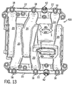
- Figure 13 shows an intake manifold 410 for a V-6 engine having two banks of cylinders, each bank having an air assist passageway to feed the three cylinders in that bank.
- the air assist port is disposed between two of the three cylinders in each bank (and hence between two induction air passageways and their associated injector pockets), with one cylinder (and passageway and associated pocket) on one side of the air assist port and two cylinders (and their associated induction air passageways and associated injectors) on the other side of the air assist port.
- the system is the same as that described herein for the manifold of Figure 1.
- air assist passageways and injector pockets are preferably formed integrally with the manifold as shown in the arrangements of Figures 1-7 and 11-13, they can be separately formed and attached to the manifold at a later date. This has the advantage of permitting the air assist passageway and the manifold to be made more precisely and positioned more accurately. In this arrangement, the air assist passageway and injector pockets would preferably be removably fastened to the intake manifold itself. Figures 8-10 illustrate such an arrangement.
- Figures 8- 10 illustrate an air assist rail for a manifold 110 similar to manifold 12, but having a separate air assist passageway formed as a separate air assist rail and removably attached to the manifold.
- manifold 110 to which they are attached is the same in every respect to that of the Figure 1 manifold 12, but does not have the integral air assist passageway 22 or integral injector pockets 18 as shown most clearly in Figure 5.
- an air assist rail 50 with associated injector pockets 118 is separately formed and attached to the modified manifold 110 as best shown in Figure 10.
- manifold 110 is designed for a V-8 engine, and has two sets of induction air passageways 120, one for each bank of cylinders, each set having four passageways 120, and each passageway being associated with one of the cylinders in that bank.
- Figure 9 illustrates the arrangement of a typical set of injector pockets together with its associated air assist passageway 122.
- Each set of induction air passageways 120 on each bank has an associated air assist rail 50 that is in fluid communication with all the fuel injectors 16 of that set. While Figure 9 shows only a single fuel injector 16 in its associated fuel injector pocket 118 it is understood that each of the injector pockets described herein will be similarly equipped.
- the air assist passageway 122 for each set of induction air passageways 120 is circular, and has a longitudinal axis 134 that extends through and intersects the fuel injector pockets 118 in each set.
- Each air assist passageway 122 and its longitudinal axis 134 preferably intersects the fuel injector pockets at a right angle to the longitudinal central axis 136 of its associated fuel injector pockets 118 to provide for better distribution of the assist air.
- air assist passageway 122 preferably intersects longitudinal axis 136 of the fuel injector pockets 118.
- longitudinal axis 134 substantially intersects longitudinal central axis 136 of the fuel injector pockets.
- Fuel injector pockets 118 in each bank are preferably arranged in a substantially straight line, and hence their associated air assist passageway 122 (which is preferably straight as well) intersects each of its fuel injector pockets 118 at the same location within each pocket.
- Fuel injectors 16 are supported in pockets 118 on two flexible seals, shown here as O-rings 138, that define air assist chambers 140 between the outer surface of the fuel injectors 16 and the inner surface of fuel injector pockets 118. These seals both support the fuel injector and prevent the pressurized assist air from escaping the fuel injector pocket. Air assist passageways 122 enter into and exit fuel injector pockets 118 in air assist chambers 140 at a point between the upper and lower flexible seals 138. In this manner, the assist air is held within the injector pockets and is prevented from leaking out.
- Air is introduced into air assist passageway of the air assist rail 50 at a point between the two inner fuel injectors on each bank.
- an air assist port 142 (similarly formed and constructed in all respects to air assist port 42), is provided in air assist passageway 122. It is through this port that assist air under pressure is supplied to air assist passageway 122.
- This port may be connected to an assist air line by any of a variety of conventional means well known to those skilled in the art.
- a single port is provided through which air is introduced. Once introduced into air assist port 142, the air is diverted in two directions, following both a leftward and a rightward path, each path directing the assist air toward a pair of associated cylinders in the bank of cylinders associated with that air assist passageway.
- each pocket 118 on the air assist rail has an associated circular sealing surface 52 extending from the bottom of injector pockets 118 that abuts a similarly circular opening 54 on manifold 110.
- a sealing material such as sealing rings or gaskets may be disposed between each of these surfaces 52 and associated openings 54.
- Air assist rail 50 is fixed to manifold 110 using a plurality of fasteners, preferably removable screw-type fasteners, and most preferably (and as shown here) machine screws 56.
- each injector pocket is provided with an ear 58 that extends upward from the pocket and has an opening 60 through which the fastener is inserted.
- the fastener is screwed into manifold 110, as shown in Figure 10, and air assist rail 50 is thereby fixed to manifold 110.
- air assist port 142 of the preferred embodiment is disposed between two pairs of injector pockets and thus feeds equal numbers of cylinders on each path, it can be disposed between any two adjacent injector pockets 118 and still provide substantial advantages over the prior art arrangement in which assist air was supplied only to one end of the air assist passageway.
- air assist rail 50 of Figures 8-10 may be used with a variety of engine arrangements, including a straight six engine, a V-4 engine, and a V-6 engine and is disposed in a similar location on the manifolds of these engines as the assist air passageways of Figures 11-13.
- the air assist passageways and the fuel injector pockets are preferably formed in a single molding operation, whether they are formed as a part of the entire manifold 12, 210, 310 or 410, or whether they are formed as a separate air assist rail 50.
- Figures 14-15 illustrate the preferred arrangement. For clarity, the mass of the mold cavity that forms the outside surface of the air assist passageways and the fuel injector pockets has been removed, and only the salient parts -- the bosses that form the fuel injector pockets and the pins that form the air assist passageways -- are shown in detail.
- the rest of the mold forming the outer surface of manifold 12, 210, 310 or 410 (if formed integrally with the manifold) or the air assist rails 50 (if formed separate from the manifold) are configured in a conventional manner well known to those skilled in the art.
- the arrangement of mold, bosses and pins described below can be used to form the injector pockets and air assist passageways of either the unitary manifold (best shown in Figures 1, and 11-13), or the separate air assist rail 50 (best shown in Figure 8).
- a first injection mold portion 62 and a second injection mold portion 64 collectively define the outer surface of the injector pockets and the air assist passageways.
- First mold portion 62 forms a portion of the lower outer surface of the manifold 12, 210, 310 or 410, or air assist rail 50 if it is being formed separately.
- Second mold portion 64 forms the upper outer surface of the manifold 12, 210, 310 or 410, or air assist rail 50 if it is being formed separately.
- First and second mold portions 62 and 64 abut one another to collectively define the mold cavity that shapes the outer surface of the manifolds or fuel rail.
- Second mold portion 64 has a plurality of injector pocket bosses 66 extending into the mold cavity from an interior surface thereof to form an upper portion of the injector bosses.
- First mold portion also has a plurality of bosses 68 that abut bosses 66 to form a bottom portion of fuel injector pockets.
- Bosses 66, 68 substantially define the interior surface of the fuel injector pockets.
- Bosses 66, 68 are preferably arranged in a straight line and have parallel longitudinal axes, thus providing fuel injector pockets in the finished manifold or air assist rail that are parallel.
- Each boss 66 has a passageway 70 defined therethrough. These passageways are coaxial to thereby define a continuous and hollow cylindrical opening extending through all the bosses 66.
- An additional air assist port boss 72 also extends into the mold cavity and has a passageway 74 extending therethrough that is coaxial with the passageways 70 extending through each of the bosses 66 that form the interior of the injector pockets.
- passageways 70 that pass through bosses 66 and passageway 74 that pass through boss 72 define a single tubular passageway extending through all the bosses 66 and 72.
- the passageways 70 and 74 are configured to receive and support two air assist passageway pins 76 and 78 that are inserted into the mold cavity.
- Pins 76 and 78 are preferably circular and meet in the middle, one of the pins having a recess 80 and the other having a protrusion 82 that, when properly abutted and mated, cause the pins to collectively define a continuous cylindrical body.
- the protrusion and recess keep their respective pins in alignment during the injection molding process to thereby form a continuous air assist passageway extending through all the injector pockets.
- Pins 76 and 78 collectively define the interior surface of the air assist passageway extending between the fuel injector pockets, as shown in Figures 1-13.
- first mold portion 62 and second mold portion 64 are closed to define a mold cavity.
- This cavity defines the outer surface of an intake manifold with integral air assist passageway and fuel injector pockets, or an assist air rail if it is to be formed separately.
- air assist passageway pins 76 and 78 are inserted into the mold cavity and through the injector pocket bosses that extend inwardly into the mold cavity from second mold portion. The pins are inserted through the bosses' passageways until they abut each other, engaging their mating protrusions and recesses. As shown in Fig. 14, at least a portion of the length of each pin 76, 78 is completely surrounded by the fuel injector pockets through which it passes.
- the mold is then filled with a material such as plastic, preferably mineral reinforced, and allowed to cool.
- the pins are then withdrawn from the mold cavity and the cavity is opened. Once the cavity is opened, the manifold or air assist rail can be removed and the air assist port can be drilled or milled if it was not formed as a part of the molding process.
- the two open ends of each air assist passageway defined by the pins are then plugged to prevent assist air from leaking out in use.
- the manifolds and air assist rails are preferably made from plastic, more preferably a mineral fiber reinforced plastic to provide dimensional stability and strength in the hot under-hood environments experienced by contemporary internal combustion engines.
- intake manifolds have been made of light metals, such as aluminum or magnesium alloys, which would be satisfactory in the present application but are not preferred due to their weight.
- the flexible seals while shown herein as O-rings, can be rectangular, oval or lobed seals depending upon the preferred degree of sealing.
Landscapes
- Engineering & Computer Science (AREA)
- Chemical & Material Sciences (AREA)
- Combustion & Propulsion (AREA)
- Mechanical Engineering (AREA)
- General Engineering & Computer Science (AREA)
- Fuel-Injection Apparatus (AREA)
Abstract
Description
Claims (18)
- An intake system for an internal combustion engine having at least one bank of cylinders adjacent to each other, the system comprising:a first plurality of air induction passageways couplable to the at least one bank of cylinders;a first plurality of fuel injector pockets, each fluidly coupled with one of the first plurality of air induction passageways; anda first air assist passageway fluidly coupled with the first plurality of fuel injector pockets to communicate assist air to each of the fuel injector pockets, wherein the first air assist passageway has a first assist air feed port for receiving assist air and the first assist air port is disposed between at least two of the first plurality of fuel injector pockets.
- The intake system of claim 1, wherein the air intake system further comprises:a second plurality of air induction passageways couplable to at least another bank of cylinders of the internal combustion engine;a second plurality of fuel injector pockets, each fluidly coupled with one of the second plurality of air induction passageways; anda second air assist passageway fluidly coupled with the first plurality of fuel injector pockets to communicate assist air to each of the fuel injector pockets, wherein the air assist passageway has a second assist air feed port for receiving assist air and the second assist air port is disposed between at least two of the second plurality of fuel injector pockets.
- The intake system of claim 2, wherein the first and second pluralities of air induction passageways each include at least three passageways, each of the at least three passageways being couplable to a corresponding cylinder of the first and second banks of cylinders, respectively.
- The intake system of claim 3, wherein the first and second pluralities of air induction passageways each include at least four passageways, each of the at least four passageways being couplable to a corresponding cylinder of the first and second banks of cylinders, respectively.
- The intake system of claim 1, wherein the first plurality of air induction passageways include at least four passageways, each of the at least four passageways being couplable to a corresponding cylinder of the first bank of cylinders.
- The intake system of claim 1, wherein the first plurality of injector pockets, the first plurality of air induction passageways, the first air assist passageway and the first assist air feed port are formed as an intake manifold.
- The air intake system of claim 6, wherein the first plurality of injector pockets, the first plurality of air induction passageways, the first air assist passageway and the first assist air feed port are injection molded in an integral form.
- An intake system for an internal combustion engine having at least one bank of cylinders adjacent to each other, the system comprising:a first plurality of air induction passageways couplable to the at least one bank of cylinders;a first plurality of fuel injector pockets, each fluidly coupled with one of the first plurality of air induction passageways; anda first air assist passageway fluidly coupled with the first plurality of fuel injector pockets to communicate assist air to each of the fuel injector pockets, wherein each of the first plurality of fuel injector pockets has a central longitudinal axis, and further wherein the first air assist passageway intersects each of the central axes of the plurality of fuel injector pockets.
- The intake system of claim 8, wherein the first air assist passageway has a longitudinal axis, and wherein the first longitudinal axis of the first air assist passageway substantially intersects the first longitudinal axes of the first plurality of fuel injector pockets.
- The intake system of claim 8, wherein the first air assist passageway intersects the plurality of fuel injector pockets between two circumferential seats on each of the plurality of fuel injector pockets, and further wherein the two circumferential seats are engageable with two flexible seals disposable between the two circumferential seats and a fuel injector.
- The intake system of claim 10, wherein the two flexible seals are O-rings.
- The intake system of claim 11, wherein the intake system further includes a plenum and a plurality of induction air passageways having a plurality of inlets disposed in the plenum and a plurality of outlets, each said outlet disposed adjacent to a corresponding one of the plurality of fuel injector pockets.
- The intake system of claim 12, wherein the intake system is integrally molded.
- An intake system for an internal combustion engine having at least one bank of cylinders adjacent to each other, the system comprising:a first plurality of fuel injector pockets; anda first air assist passageway fluidly coupled between and integrally formed with each of the first plurality of fuel injector pockets to communicate assist air to each of the fuel injector pockets; andan air assist port disposed in the air assist passageway to receive and transmit the assist air to the injector pockets, wherein each of the first plurality of fuel injector pockets has a central longitudinal axis, and further wherein the first air assist passageway intersects each of the central axes of the plurality of fuel injector pockets.
- The air intake system of claim 14 wherein the air assist port is disposed between equal numbers of fuel injector pockets.
- The air intake system of claim 15 wherein the longitudinal axis of the air assist passageway has a longitudinal axis, and further wherein the air assist passageway's longitudinal axis substantially intersects the longitudinal axes of the plurality of fuel injector pockets.
- The air intake system of claim 16 wherein the air assist passageway and the fuel injector pockets are integrally formed as an air intake rail.
- The air intake system of claim 17 wherein the fuel rail is injection molded from a mineral-filled plastic.
Applications Claiming Priority (2)
| Application Number | Priority Date | Filing Date | Title |
|---|---|---|---|
| US369471 | 1999-08-06 | ||
| US09/369,471 US6553980B1 (en) | 1999-08-06 | 1999-08-06 | Center feed of air for air assist fuel injector |
Publications (3)
| Publication Number | Publication Date |
|---|---|
| EP1074730A2 true EP1074730A2 (en) | 2001-02-07 |
| EP1074730A3 EP1074730A3 (en) | 2002-01-02 |
| EP1074730B1 EP1074730B1 (en) | 2003-04-09 |
Family
ID=23455604
Family Applications (1)
| Application Number | Title | Priority Date | Filing Date |
|---|---|---|---|
| EP00202772A Expired - Lifetime EP1074730B1 (en) | 1999-08-06 | 2000-08-04 | Center feed of air for assist fuel injector |
Country Status (3)
| Country | Link |
|---|---|
| US (1) | US6553980B1 (en) |
| EP (1) | EP1074730B1 (en) |
| DE (1) | DE60002018T2 (en) |
Families Citing this family (5)
| Publication number | Priority date | Publication date | Assignee | Title |
|---|---|---|---|---|
| GB2389147A (en) * | 2002-05-31 | 2003-12-03 | Man B & W Diesel Ltd | I.c. engine air manifold arrangement |
| US7275511B1 (en) * | 2006-07-26 | 2007-10-02 | Gm Global Technology Operations, Inc. | Intake manifold assembly |
| CN101493058B (en) * | 2008-12-08 | 2011-12-07 | 上海华普汽车有限公司 | Inlet manifold assembly |
| FR2950396B1 (en) * | 2009-09-22 | 2012-04-27 | Mark Iv Systemes Moteurs Sa | FUNCTIONAL MODULE INTEGRATING A DISTRIBUTOR AND INJECTION RAMP AND METHOD FOR MANUFACTURING THE SAME |
| JP6879068B2 (en) * | 2017-06-14 | 2021-06-02 | トヨタ紡織株式会社 | Intake manifold |
Family Cites Families (21)
| Publication number | Priority date | Publication date | Assignee | Title |
|---|---|---|---|---|
| US2833260A (en) * | 1955-05-31 | 1958-05-06 | Gen Motors Corp | Atmospheric vent for fuel injection nozzle |
| US2893365A (en) * | 1956-05-31 | 1959-07-07 | Gen Motors Corp | Fuel injection means |
| US3788287A (en) | 1972-02-18 | 1974-01-29 | Gen Motors Corp | Fuel injection system |
| JPS5845597B2 (en) * | 1977-05-04 | 1983-10-11 | トヨタ自動車株式会社 | Internal combustion engine fuel delivery device |
| JPS5549566A (en) * | 1978-10-02 | 1980-04-10 | Aisan Ind Co Ltd | Mixture feeding apparatus for interval combustion engine |
| GB2203487A (en) * | 1987-04-03 | 1988-10-19 | Ford Motor Co | A fuel injection system component |
| JPH03926A (en) * | 1989-05-29 | 1991-01-07 | Honda Motor Co Ltd | Intake system for multicylinder internal combustion engine |
| JPH0422712A (en) * | 1990-05-17 | 1992-01-27 | Mazda Motor Corp | Suction device of engine |
| DE4038509A1 (en) | 1990-12-03 | 1992-06-11 | Mann & Hummel Filter | INTAKE DISTRIBUTOR FOR AN INTERNAL COMBUSTION ENGINE |
| GB2273130B (en) * | 1992-12-07 | 1995-12-13 | Nippon Denso Co | Fuel injection system for multi-cylinder internal combustion engine |
| FR2704601B1 (en) * | 1993-04-26 | 1995-07-13 | Renault | Air supply system for fuel injectors of the air mantle type fitted to an internal combustion engine. |
| DE4315129C2 (en) * | 1993-05-07 | 1999-01-28 | Porsche Ag | Air intake system of an internal combustion engine |
| US5623904A (en) * | 1995-05-16 | 1997-04-29 | Yamaha Hatsudoki Kabushiki Kaisha | Air-assisted fuel injection system |
| DE19522074A1 (en) * | 1995-06-17 | 1996-12-19 | Bosch Gmbh Robert | Fuel supply device for an internal combustion engine |
| US5785251A (en) * | 1995-06-27 | 1998-07-28 | Siemens Automotive Corporation | Air assist fuel injector |
| US5657733A (en) * | 1996-01-22 | 1997-08-19 | Siemens Electroic Limited | Fuel injector mounting for molded intake manifold with integrated fuel rail |
| KR970070528A (en) * | 1996-04-18 | 1997-11-07 | 김영귀 | Automotive injectors for stratification of combustion chamber mixers |
| JP3127832B2 (en) * | 1996-08-01 | 2001-01-29 | トヨタ自動車株式会社 | Air assist device for internal combustion engine |
| DE19635535C2 (en) * | 1996-09-02 | 1998-07-23 | Daimler Benz Ag | Cast cylinder head of a multi-cylinder internal combustion engine |
| US6371387B1 (en) * | 1997-03-13 | 2002-04-16 | Siemens Automotive Corporation | Air assist metering apparatus and method |
| US6178632B1 (en) * | 1999-08-06 | 2001-01-30 | Siemens Canada Limited | Method for manufacturing air assist passageways for fuel insector |
-
1999
- 1999-08-06 US US09/369,471 patent/US6553980B1/en not_active Expired - Fee Related
-
2000
- 2000-08-04 DE DE60002018T patent/DE60002018T2/en not_active Expired - Fee Related
- 2000-08-04 EP EP00202772A patent/EP1074730B1/en not_active Expired - Lifetime
Also Published As
| Publication number | Publication date |
|---|---|
| EP1074730B1 (en) | 2003-04-09 |
| DE60002018D1 (en) | 2003-05-15 |
| EP1074730A3 (en) | 2002-01-02 |
| DE60002018T2 (en) | 2004-01-08 |
| US6553980B1 (en) | 2003-04-29 |
Similar Documents
| Publication | Publication Date | Title |
|---|---|---|
| EP1860319B1 (en) | Dual-system fuel injection engine | |
| US4971014A (en) | Fuel delivery rail assembly | |
| EP0876550B1 (en) | Fuel injector mounting for molded intake manifold with integrated fuel rail | |
| KR101793764B1 (en) | Gas distribution manifold in the cylinder head of an engine, set comprising a distribution manifold and an engine cylinder head | |
| US7100559B2 (en) | Engine air intake manifold | |
| US9574522B2 (en) | Assembly with cylinder head having integrated exhaust manifold and method of manufacturing same | |
| EP1074732B1 (en) | Method for manufacturing air assist passageways and injector pockets | |
| EP1074730B1 (en) | Center feed of air for assist fuel injector | |
| US6571759B2 (en) | Resin intake manifolds and manufacturing process thereof | |
| KR20180094795A (en) | Cylinder head | |
| CN114635816B (en) | Integral fuel rail structure and manufacturing method | |
| US10975812B2 (en) | Method and system for manufacturing a family of intake manifolds for a family of internal combustion engines | |
| EP0245009B1 (en) | A fuel rail | |
| CN102200046B (en) | Internal combustion engine exhaust cooling system | |
| US10247150B1 (en) | Outboard motor powerhead section and fuel delivery system | |
| US7900442B2 (en) | Engine including secondary air supply apparatus | |
| CN100467847C (en) | Cylinder head with cooling channel system for reciprocating internal combustion engines | |
| JPH09327760A (en) | Cooling device of die | |
| US10161368B1 (en) | Outboard motor powerhead section and fuel delivery system having low-profile fuel rail | |
| US20080313904A1 (en) | Three-piece lower manifold for a V-style engine intake manifold | |
| US7665449B2 (en) | V-type engine | |
| JPH0544593A (en) | Manufacture of fuel distributing pipe made of synthetic resin | |
| GB2266923A (en) | Internal combustion engine fuel supply. | |
| WO2020145155A1 (en) | Cylinder head |
Legal Events
| Date | Code | Title | Description |
|---|---|---|---|
| PUAI | Public reference made under article 153(3) epc to a published international application that has entered the european phase |
Free format text: ORIGINAL CODE: 0009012 |
|
| AK | Designated contracting states |
Kind code of ref document: A2 Designated state(s): AT BE CH CY DE DK ES FI FR GB GR IE IT LI LU MC NL PT SE Kind code of ref document: A2 Designated state(s): DE FR GB |
|
| AX | Request for extension of the european patent |
Free format text: AL;LT;LV;MK;RO;SI |
|
| 17P | Request for examination filed |
Effective date: 20010731 |
|
| PUAL | Search report despatched |
Free format text: ORIGINAL CODE: 0009013 |
|
| AK | Designated contracting states |
Kind code of ref document: A3 Designated state(s): AT BE CH CY DE DK ES FI FR GB GR IE IT LI LU MC NL PT SE |
|
| AX | Request for extension of the european patent |
Free format text: AL;LT;LV;MK;RO;SI |
|
| 17Q | First examination report despatched |
Effective date: 20020211 |
|
| RAP1 | Party data changed (applicant data changed or rights of an application transferred) |
Owner name: SIEMENS VDO AUTOMOTIVE INC. |
|
| GRAH | Despatch of communication of intention to grant a patent |
Free format text: ORIGINAL CODE: EPIDOS IGRA |
|
| AKX | Designation fees paid |
Free format text: DE FR GB |
|
| GRAH | Despatch of communication of intention to grant a patent |
Free format text: ORIGINAL CODE: EPIDOS IGRA |
|
| GRAA | (expected) grant |
Free format text: ORIGINAL CODE: 0009210 |
|
| AK | Designated contracting states |
Designated state(s): DE FR GB |
|
| PG25 | Lapsed in a contracting state [announced via postgrant information from national office to epo] |
Ref country code: FR Free format text: LAPSE BECAUSE OF FAILURE TO SUBMIT A TRANSLATION OF THE DESCRIPTION OR TO PAY THE FEE WITHIN THE PRESCRIBED TIME-LIMIT Effective date: 20030409 |
|
| REG | Reference to a national code |
Ref country code: GB Ref legal event code: FG4D |
|
| REG | Reference to a national code |
Ref country code: IE Ref legal event code: FG4D |
|
| PGFP | Annual fee paid to national office [announced via postgrant information from national office to epo] |
Ref country code: DE Payment date: 20031020 Year of fee payment: 4 |
|
| PLBE | No opposition filed within time limit |
Free format text: ORIGINAL CODE: 0009261 |
|
| STAA | Information on the status of an ep patent application or granted ep patent |
Free format text: STATUS: NO OPPOSITION FILED WITHIN TIME LIMIT |
|
| EN | Fr: translation not filed | ||
| 26N | No opposition filed |
Effective date: 20040112 |
|
| REG | Reference to a national code |
Ref country code: IE Ref legal event code: MM4A |
|
| PG25 | Lapsed in a contracting state [announced via postgrant information from national office to epo] |
Ref country code: GB Free format text: LAPSE BECAUSE OF NON-PAYMENT OF DUE FEES Effective date: 20040804 |
|
| PG25 | Lapsed in a contracting state [announced via postgrant information from national office to epo] |
Ref country code: DE Free format text: LAPSE BECAUSE OF NON-PAYMENT OF DUE FEES Effective date: 20050301 |
|
| GBPC | Gb: european patent ceased through non-payment of renewal fee |
Effective date: 20040804 |