EP1074347A2 - Grinding wheel having dust discharge impelling blades - Google Patents
Grinding wheel having dust discharge impelling blades Download PDFInfo
- Publication number
- EP1074347A2 EP1074347A2 EP00402179A EP00402179A EP1074347A2 EP 1074347 A2 EP1074347 A2 EP 1074347A2 EP 00402179 A EP00402179 A EP 00402179A EP 00402179 A EP00402179 A EP 00402179A EP 1074347 A2 EP1074347 A2 EP 1074347A2
- Authority
- EP
- European Patent Office
- Prior art keywords
- shank
- dust
- grinding
- impelling
- grinding wheel
- Prior art date
- Legal status (The legal status is an assumption and is not a legal conclusion. Google has not performed a legal analysis and makes no representation as to the accuracy of the status listed.)
- Granted
Links
- 239000000428 dust Substances 0.000 title claims abstract description 163
- 238000007599 discharging Methods 0.000 claims abstract description 56
- 239000000463 material Substances 0.000 claims description 19
- 239000000853 adhesive Substances 0.000 claims description 7
- 230000001070 adhesive effect Effects 0.000 claims description 7
- 238000003466 welding Methods 0.000 abstract description 11
- 238000005304 joining Methods 0.000 abstract description 8
- 238000001816 cooling Methods 0.000 abstract description 5
- 239000002245 particle Substances 0.000 description 13
- 229910000831 Steel Inorganic materials 0.000 description 10
- 239000010959 steel Substances 0.000 description 10
- 229910052782 aluminium Inorganic materials 0.000 description 7
- XAGFODPZIPBFFR-UHFFFAOYSA-N aluminium Chemical compound [Al] XAGFODPZIPBFFR-UHFFFAOYSA-N 0.000 description 7
- 230000006698 induction Effects 0.000 description 7
- 239000000057 synthetic resin Substances 0.000 description 7
- 229920003002 synthetic resin Polymers 0.000 description 7
- 238000011109 contamination Methods 0.000 description 4
- 230000000694 effects Effects 0.000 description 4
- 230000001965 increasing effect Effects 0.000 description 4
- 238000012423 maintenance Methods 0.000 description 3
- RYGMFSIKBFXOCR-UHFFFAOYSA-N Copper Chemical compound [Cu] RYGMFSIKBFXOCR-UHFFFAOYSA-N 0.000 description 2
- PXHVJJICTQNCMI-UHFFFAOYSA-N Nickel Chemical compound [Ni] PXHVJJICTQNCMI-UHFFFAOYSA-N 0.000 description 2
- 239000011449 brick Substances 0.000 description 2
- 239000004567 concrete Substances 0.000 description 2
- 229910052802 copper Inorganic materials 0.000 description 2
- 239000010949 copper Substances 0.000 description 2
- 230000003247 decreasing effect Effects 0.000 description 2
- 239000010438 granite Substances 0.000 description 2
- 239000004579 marble Substances 0.000 description 2
- 229910000906 Bronze Inorganic materials 0.000 description 1
- 239000010974 bronze Substances 0.000 description 1
- 239000000919 ceramic Substances 0.000 description 1
- 229910017052 cobalt Inorganic materials 0.000 description 1
- 239000010941 cobalt Substances 0.000 description 1
- GUTLYIVDDKVIGB-UHFFFAOYSA-N cobalt atom Chemical compound [Co] GUTLYIVDDKVIGB-UHFFFAOYSA-N 0.000 description 1
- KUNSUQLRTQLHQQ-UHFFFAOYSA-N copper tin Chemical compound [Cu].[Sn] KUNSUQLRTQLHQQ-UHFFFAOYSA-N 0.000 description 1
- 238000005520 cutting process Methods 0.000 description 1
- 229910003460 diamond Inorganic materials 0.000 description 1
- 239000010432 diamond Substances 0.000 description 1
- 230000002708 enhancing effect Effects 0.000 description 1
- -1 etc. Substances 0.000 description 1
- 230000004907 flux Effects 0.000 description 1
- 238000004519 manufacturing process Methods 0.000 description 1
- 229910052751 metal Inorganic materials 0.000 description 1
- 239000002184 metal Substances 0.000 description 1
- 239000007769 metal material Substances 0.000 description 1
- 150000002739 metals Chemical class 0.000 description 1
- 229910052759 nickel Inorganic materials 0.000 description 1
- 229920005989 resin Polymers 0.000 description 1
- 239000011347 resin Substances 0.000 description 1
Images


Classifications
-
- B—PERFORMING OPERATIONS; TRANSPORTING
- B24—GRINDING; POLISHING
- B24B—MACHINES, DEVICES, OR PROCESSES FOR GRINDING OR POLISHING; DRESSING OR CONDITIONING OF ABRADING SURFACES; FEEDING OF GRINDING, POLISHING, OR LAPPING AGENTS
- B24B5/00—Machines or devices designed for grinding surfaces of revolution on work, including those which also grind adjacent plane surfaces; Accessories therefor
-
- B—PERFORMING OPERATIONS; TRANSPORTING
- B24—GRINDING; POLISHING
- B24B—MACHINES, DEVICES, OR PROCESSES FOR GRINDING OR POLISHING; DRESSING OR CONDITIONING OF ABRADING SURFACES; FEEDING OF GRINDING, POLISHING, OR LAPPING AGENTS
- B24B55/00—Safety devices for grinding or polishing machines; Accessories fitted to grinding or polishing machines for keeping tools or parts of the machine in good working condition
- B24B55/06—Dust extraction equipment on grinding or polishing machines
- B24B55/10—Dust extraction equipment on grinding or polishing machines specially designed for portable grinding machines, e.g. hand-guided
- B24B55/102—Dust extraction equipment on grinding or polishing machines specially designed for portable grinding machines, e.g. hand-guided with rotating tools
-
- B—PERFORMING OPERATIONS; TRANSPORTING
- B24—GRINDING; POLISHING
- B24D—TOOLS FOR GRINDING, BUFFING OR SHARPENING
- B24D5/00—Bonded abrasive wheels, or wheels with inserted abrasive blocks, designed for acting only by their periphery; Bushings or mountings therefor
-
- B—PERFORMING OPERATIONS; TRANSPORTING
- B24—GRINDING; POLISHING
- B24D—TOOLS FOR GRINDING, BUFFING OR SHARPENING
- B24D7/00—Bonded abrasive wheels, or wheels with inserted abrasive blocks, designed for acting otherwise than only by their periphery, e.g. by the front face; Bushings or mountings therefor
- B24D7/06—Bonded abrasive wheels, or wheels with inserted abrasive blocks, designed for acting otherwise than only by their periphery, e.g. by the front face; Bushings or mountings therefor with inserted abrasive blocks, e.g. segmental
Definitions
- Conventional grinding wheels 90 and 100 for use in grinding apparatus comprise plate type shanks 91 and 101 connected with a shaft of electric motor, and grinding tips 92 and 102 disposed fixedly in single or double circumferential array on shanks 91 and 101 by means of welding or joining, as shown in FIGS. 11 and 12.
- each grinding tip and the end portion of each dust discharge-impelling blade for adhering corresponding grinding tip are bent diagonally from the circumferential direction to increase contacting area between the grinding tips and the materials to be ground.
- steel, aluminum, or synthetic resin layers 53 and 63 for fixing the grinding tips 79 can be used to replace only grinding tip portions without replacing the grinding wheel 70 as a whole when the grinding tips 79 are completely defaced, and thereby reducing the replacing and maintenance costs of the grinding wheel machine.
Abstract
Description
- The present invention relates to a grinding wheel for use in a grinding apparatus for grinding various materials such as brick, concrete, granite, marble, etc., and more particularly to a grinding wheel having dust discharge impelling blades capable of impelling to discharge the dust produced during grinding operation to the dust collection machine to decrease dispersing the dust in the air, and increase cooling efficiency of the grinding wheel, thereby enhancing the grinding ability and the life of the grinding wheel.
-
Conventional grinding wheels plate type shanks grinding tips shanks -
Grinding tips - On the
shanks round shape holes shanks Numerals 94 and 104 are rim portions. - In operation, the
grinding wheels grinding tips grinding tips round shape holes - However, at this time, since the air induction velocity of the dust collection tube of the dust collection machine is slower than the moving velocity of the grinding tips as noted above, i.e., the air induction force of the dust collection machine is smaller than the centrifugal force of grinding particles or dust, a large amount of grinding particles or dust was leaked out beyond the limits of the dust inlet portion of the dust collection machine disposed on the
grinding wheels - Further, since the air induction velocity for inducting dust into the dust collection tube of the dust collection machine is abruptly decreased to about 2m/sec at a lower surface of the
grinding tips - Also, since the
grinding tips grinding tips - It is an object of the present invention to provide a grinding wheel having dust discharge-impelling blades which are capable of impelling to discharge the dust produced during grinding operation to a dust collection machine to decrease dispersing the dust in the air and thereby to prevent the dispersed dust from giving rise to the bad effects to users' health and the contamination of environment.
- It is the other object of the present invention to provide a grinding wheel having dust discharge-impelling blades which are able to increase the cooling efficiency of the grinding wheel to enhance the cutting ability and the life of the grinding wheel.
- To accomplish these objects, a grinding wheel for use in a grinding apparatus according to one embodiment of the present invention comprises a shank for connecting with a shaft of an electric motor, having a plurality of dust discharging holes disposed at given intervals in the shank and dust discharge-impelling means disposed between dust discharging holes for impelling to discharge the dust produced during grinding operation through and in cooperation with the dust discharging holes, and a plurality of grinding tips disposed fixedly at predetermined intervals on the lower surface of a circumferential portion of the shank by means of welding or joining.
- In this embodiment of the present invention, the dust discharge-impelling means is composed of a plurality of dust discharge-impelling blades formed to be slanted in the rotation direction of the shank and respectively having upper and lower surfaces disposed to define boundaries of the dust discharging holes therebetween and inclined upwardly from a horizontal plane to produce the air propelling force for discharging dust when the shank is rotated by the electric motor.
- The shank of the present invention further includes a layer for fixing the grinding tips disposed on the lower surface of the shank.
- It is desirable that the layer is fixed by heat resistance adhesive or screws on the lower surface of the shank.
- Alternatively, the union between the layer and the lower surface of the shank can be accomplished by female and male spiral portions formed respectively in the layer and the shank.
- Also, each of the grinding tips is disposed diagonally from circumferential direction on the line projected from the end portion of the dust discharge-impelling blade to increase contacting area between the grinding tips and materials to be ground.
- It is desirable that the width of dust discharging holes in the vicinity of the center of the shank is getting narrower than that in the vicinity of circumference thereof.
- In another embodiment of the present invention, a grinding wheel for use in a grinding apparatus comprises a shank for connecting with a shaft of an electric motor, having a plurality of dust discharging openings disposed at given intervals in the shank and opened in the circumferential portion of the shank and dust discharge-impelling means disposed between the dust discharging openings for impelling to discharge the dust produced during grinding operation through and in cooperation with the dust discharging openings, and a plurality of grinding tips disposed fixedly at predetermined intervals on the lower surface of the end portion of dust discharge-impelling means by means of welding or joining.
- In this embodiment of the present invention, the dust discharge-impelling means is composed of a plurality of dust discharge-impelling blades formed to be bent at a given radius in rotation direction of the shank and respectively having upper and lower surfaces disposed to define the boundaries of the dust discharging openings therebetween and inclined upwardly from a horizontal plane to produce the air propelling force for discharging dust when the shank is rotated by the electric motor.
- It is desirable that each grinding tip and the end portion of each dust discharge-impelling blade for adhering corresponding grinding tip are bent diagonally from the circumferential direction to increase contacting area between the grinding tips and the materials to be ground.
- The shank of the present invention further includes a layer for fixing a plurality of grinding tips disposed respectively on the lower surfaces of the end portions of dust discharge-impelling blades.
- It is desirable that the layer is fixed by heat resistance adhesive or screws on the lower surface of the end portion of each dust discharge-impelling blade.
- In the other embodiment of the present invention, a grinding wheel for use in an apparatus for grinding materials comprises a shank for connecting with a shaft of electric motor, having a plurality of dust discharging holes disposed at given intervals in the shank, a dust discharge-impelling means disposed fixedly under the dust discharging holes of the shank for impelling to discharge the dust produced during grinding operation through the dust discharging holes, and a plurality of grinding tips disposed fixedly at predetermined intervals on the lower surface of a circumferential portion of shank by means of welding or joining.
- In this embodiment of the present invention, the dust discharge-impelling means is composed of a plurality of dust discharge-impelling blades disposed to be slanged in rotation direction of the shank under the dust discharging holes and inclined upwardly from a horizontal plane to produce the air propelling force for discharging dust when the shank is rotated by the electric motor.
- The shank of the present invention further includes a layer for fixing the grinding tips disposed on the lower surface of the shank.
- It is desirable that the layer is fixed by heat resistance adhesive or screws on the lower surface of the shank.
- Alternatively, the union between the layer and the lower surface of the shank can be accomplished by female and male spiral portions formed respectively in the layer and the shank.
- The above objects and other advantages of the present invention will become more apparent by describing in detail preferred embodiments thereof with reference to the attached drawings in which:
- FIG.1 is a perspective view of a grinding wheel for use in a grinding apparatus according to one embodiment of the present invention;
- FIG.2 is a cross-sectional view of the grinding wheel of the invention shown in FIG.1;
- FIG.3 is a bottom view of the grinding wheel of the invention shown in FIG.1;
- FIG.4 is a cross-sectional view of a grinding wheel of the invention having a steel layer for fixing the grinding tips;
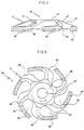
- FIG.5 and FIG.6 are front and bottom views of a grinding wheel for use in a grinding apparatus according to another embodiment of the present invention;
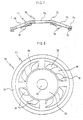
- FIG. 7 and FIG. 8 respectively illustrate a cross -sectional view and a top plan view of a grinding wheel for use in grinding apparatus according to the other embodiment of the present invention;
- FIG.9A respectively illustrates partial cross -sectional views of the grinding wheel of the present invention illustrating a state that a layer for fixing grinding tips is fixed on the lower surface of the shank.
- FIG. 9B illustrates a detailed view of 'A' portion in Fig. 9A.
- FIG.10A illustrates partial cross- sectional views of the grinding wheel of the present invention illustrating a state that a layer for fixing grinding tips is fixed on the lower surface of the shank.
- FIG. 10B illustrates a detailed view OF 'B' portion in FIG. 10A.
- FIG.11 and FIG. 12 respectively illustrate bottom views of conventional grinding wheels for use in a grinding apparatus, each of which grinding tip is disposed in single or double circumferential array on the shank.
-
- Now, embodiments of the present invention will be described with reference to FIG. 1 to FIG.12 in which the same components are illustrated and shown as the same numerals.
- Referring to FIG.1 to FIG.3, there is illustrated a grinding
wheel 10 for use in a grinding apparatus according to one embodiment of the present invention. - Grinding
wheel 10 comprises aplate type shank 20 for connecting with a shaft of electric motor, and a plurality ofgrinding tips 30 disposed fixedly at predetermined intervals on the lower surface of theshank 20 by means of welding or joining. - The
shank 20 according to the invention has adisc portion 22 having ahole 23 for receiving the shaft of electric motor, and a plurality ofdust discharging holes 25 disposed at given intervals around thedisc portion 22. - The
shank 20 can be made of synthetic resin, or metal materials such as aluminum, steel, copper, etc. - It is desirable that the width of each
dust discharging hole 25 in the vicinity of the center of theshank 20 is getting narrower than that in the vicinity of circumference. thereof. - Also, the
shank 20 includes a plurality of dust discharge-impelling blades 26 disposed between thedust discharging holes 25 for impelling to discharge dust produced during grinding operation through and in cooperation with thedust discharging holes 25, and arim portion 24 for adheringgrinding tips 30 on the lower surface thereof connected with thedisc portion 22 through the dust discharge-impelling blades 26. - The dust discharging-
impelling blades 26 are slanted in the rotation direction of theshank 20. - Each of the discharging-
impelling blades 26 has upper andlower surfaces dust discharging holes 25 and inclined upwardly from a horizontal plane to produce the air propelling force for discharging the dust ground by grindingtips 30 when theshank 20 is rotated by the electric motor. - In here, it is noted that besides forming the dust discharge-
impelling blades 26 in shape slanted in the rotation direction of theshank 20 as explained above, it is possible to form theblades 26 in any other streamline or straight shape to be able to produce the air propelling force for discharging the dust. - Also, as shown in FIG. 3, it is desirable that each of the
grinding tips 30 is disposed diagonally from the circumferential direction on the line projected from the end portion of the dust discharge-impelling blades 26 to increase contacting area between thegrinding tips 30 and .the materials to be ground. - As shown in FIG. 4, a
shank 20 of the present invention can include asteel layer 29 for fixing thegrinding tips 30 disposed on the lower surface of therim portion 24 of theshank 20. - The
steel layer 29 is used to adhere the grinding tips on the shank by welding in case that the shank is made of materials such as aluminum or synthetic resins which are not able to be welded. - The
steel layer 29 is fixed by heat resistance adhesive on the lower surface of theshank 20. - Also, as shown in FIG.9 and FIG.10, steel, aluminum, or
synthetic resin layers grinding tips wheels 50 and 60 as a whole whengrinding tips - In this case, a
layer 63 is fixed by screws on theshank 61, as shown in FIG. 10. - Alternatively, the union between the
layer 53 and theshank 51 can be accomplished by female andmale spiral portions layer 53 and theshank 51, as shown in FIG.9. - Referring to FIG.5 and FIG.6, there is illustrated a
grinding wheel 40 for use in a grinding apparatus according to another embodiment of the present invention. - The grinding
wheel 40 comprises ashank 41 including adisc portion 42 having ahole 43 for receiving the shaft of an electric motor, a plurality ofdust discharging openings 44 disposed at given intervals arpund thedisc portion 42 and opened in the circumferential portion of theshank 41, and a plurality of dust discharge-impellingblades 46 disposed between thedust discharging openings 44 for impelling to discharge dust produced during grinding operation through and in cooperation with thedust discharging openings 44. - The dust discharge-impelling
blades 46 are respectively formed to be bent at a given radius in the rotation direction of theshank 41. - The dust discharge-impelling
blades 46 have upper andlower surfaces dust discharging openings 44 therebetween, respectively and inclined upwardly from a horizontal plane to produce the air propelling force for discharging the dust whenshank 41 is rotated by the electric motor. - The grinding
wheel 40 further includes a plurality of grindingtips 49 disposed fixedly at predetermined intervals on the lower surface of the end portion of the dust discharge-impellingblades 46 by means of welding or joining. - It is desirable that each grinding
tip 49 and end portion of each dust discharge-impellingblade 46 for adhering corresponding grindingtip 49 are bent diagonally from circumferential direction to increase contacting area between the grindingtips 49 and the materials to be ground and thereby increasing the grinding ability of thegrinding wheel 40. - Also, as in grinding
wheel 10 shown in FIG.4, ashank 41 can include a steel layer for fixing a plurality of grinding tips disposed respectively on the lower surfaces of end portions of dust discharge-impellingblades 46 to be able to adhere the grinding tips thereon by welding in case that shank is made of materials such as aluminum or synthetic resins which are not able to be welded. - Also, as in grinding
wheels 50 and 60 shown in FIG.9 and FIG.10, a steel, aluminum, or synthetic resin layer for fixing the grindingtips 49 can be used to replace only grinding tip portions without replacing grindingwheel 40 as a whole when grindingtips 49 are completely defaced, and thereby reducing the replacing and maintenance costs of the grinding wheel machine. - Referring to FIG.7 and FIG.8, there is illustrated a
grinding wheel 70 for use in a grinding apparatus according to the other embodiment of the present invention. - A grinding
wheel 70 comprises ashank 71 including adisc portion 72 having ahole 73 for receiving the shaft of electric motor, and a plurality ofdust discharging holes 76 disposed at given intervals arounddisc portion 74. - The grinding
wheel 70 further includes a plurality of dust discharge-impellingblades 78 disposed fixedly under thedust discharging holes 76 of theshank 71 for impelling to discharge the dust produced during grinding operation through thedust discharging holes 76, and a plurality of grindingtips 73 disposed fixedly at predetermined intervals on the lower surface of a circumferential portion ofshank 71 by means of welding or joining. - It is desirable that dust discharge-impelling
blades 78 are disposed to be a slant in the rotation direction of theshank 71 underdust discharging holes 76 and inclined upwardly from a horizontal plane to produce the air propelling force for discharging the dust when theshank 71 is rotated by the electric motor. - Also, dust discharge-impelling
blades 78 can be fabricated separately or as one body with theshank 71, depending on the manufacturing condition. - Also, as in grinding
wheel 10 shown in FIG.4, theshank 71 can include asteel layer 29 for fixinggrinding tips 73 disposed on the lower surface of theshank 71 to be able to adhere grinding tips thereon by welding in case that theshank 71 is made of materials such as aluminum or synthetic resins which are not able to be welded. - Also, as in grinding
wheels 50 and 60 shown in FIG.9 and FIG.10, steel, aluminum, or synthetic resin layers 53 and 63 for fixing the grindingtips 79 can be used to replace only grinding tip portions without replacing thegrinding wheel 70 as a whole when the grindingtips 79 are completely defaced, and thereby reducing the replacing and maintenance costs of the grinding wheel machine. - Operation of grinding wheels for use in grinding apparatus according to embodiments of the present invention will be described, hereinafter.
- Since the operation of grinding
wheel 10 illustrated in FIG.1 to FIG.3 is the same as that of grindingwheels wheel 10 will be explained. - At first, when a
grinding wheel 10 is rotated at a high speed of 10,000 RPM by an electric motor on materials such as brick, concrete, granite, marble, etc., grindingtips 30 begin to grind materials. - By the grinding operation of grinding
tips 30, grinding particles or dusts are produced and discharged throughdust discharging holes 25 of ashank 20 to a dust collection machine by the air induction force of the dust collection machine. - At this time, grinding particles or dust is carried with the centrifugal force corresponding to the moving velocity of grinding
tip 30 and thereby urging to be leaked out beyond the limits of the dust inlet portion or the hood of the dust collection machine disposed on grindingwheel 10 for guiding dust to a dust collection tube of the dust collection machine. - However, since dust discharge-impelling
blades 26 also produce the air propelling force for discharging dust to the dust collection tube of the dust collection machine when ashank 20 is rotated by the electric motor, air induction velocity for discharging dust into a dust collection machine atlower surfaces 28 of grindingtips 30 is increased by five times as large as that obtained by means of only a dust collection machine, i.e., by about 10 m/sec to neutralize the centrifugal force of grinding particles or dust and thereby the produced grinding particles are prevented fundamentally from leaking out beyond the limits of the dust inlet portion and dispersing in the air to give rise to the bad effect to users' health and the contamination of environment. - Also, the removal speed of grinding particles is increased by 20 to 60% according to the kinds of materials to be ground and cooling efficiency is also enhanced.
- In this way, by repeating the operation of grinding
wheel 10, the grinding operation of materials is completed. - As apparent from the foregoing description, it can be appreciated that the present invention provides a grinding wheel having dust discharge-impelling blades which are able to impel to discharge dust produced during grinding operation to the dust collection machine to decrease dispersing dusts in the air and thereby to prevent the dispersed dusts from giving rise to the bad effect to users' health and the contamination of environment.
- Also, the present invention provides a grinding wheel having dust discharge-impelling blades which are able to increase the cooling efficiency of the grinding wheel to enhance grinding ability and the life of the grinding wheel.
Claims (17)
- A grinding wheel for use in a grinding apparatus comprising: a shank for connecting with a shaft of an electric motor, having a plurality of dust discharging holes disposed at given intervals in said shank and dust discharge-impelling meahs disposed between dust discharging holes for impelling to discharge the dust produced during the grinding operation through and in cooperation with said dust discharging holes; and
a plurality of grinding tips disposed fixedly at predetermined intervals on the lower surface of a circumferential portion of said shank,
wherein said dust discharge-impelling means is composed of a plurality of dust discharge-impelling blades formed to be slanted in rotation direction of said shank and respectively having upper and lower surfaces disposed to define boundaries of said dust discharging holes therebetween and inclined upwardly from a horizontal plane to produce the air propelling force for discharging dust when said shank is rotated by the electric motor. - The grinding wheel as claimed in claim 1, wherein said shank further includes a layer for fixing said grinding tips disposed on the lower surface of said shank.
- The grinding wheel as claimed in claim 2, wherein said layer is fixed by heat resistance adhesive on the lower surface of said shank.
- The grinding wheel as claimed in claim 2, wherein said layer is fixed by screws on the lower surface of said shank.
- The grinding wheel as claimed in claim 2, wherein the union between said layer and the lower surface of said shank is accomplished by female and male spiral portions formed respectively in said layer and said shank.
- The grinding wheel as claimed in claim 1, wherein each of said grinding tips is disposed diagonally from the circumferential direction on the line projected from the end portion of said dust discharge-impelling blades to increase the contacting area between said grinding tips and materials to be ground.
- The grinding wheel as claimed in claim 1, wherein the width of dust discharging holes in the vicinity of the center of said shank is getting narrower than that in the vicinity of circumference thereof.
- A grinding wheel for use in a grinding apparatus comprising: a shank for connecting with a shaft of an electric motor, having a plurality of dust discharging openings disposed at given intervals in the shank and opened in the circumferential portion of said shank and dust discharge-impelling means disposed between said dust discharging openings for impelling to discharge the dust produced during the grinding operation through and in cooperation with said dust discharging openings; and
a plurality of grinding tips disposed fixedly at predetermined intervals on the lower surface of the end portion of dust discharge-impelling means,
wherein said dust discharge-impelling means is composed of a plurality of dust discharge-impelling blades formed to be bent at a given radius in the rotation direction of said shank and respectively having upper and lower surfaces disposed to define boundaries of said dust discharging openings therebetween and inclined upwardly from a horizontal plane to produce the air propelling force for discharging dust when said shank is rotated by the electric motor. - The grinding wheel as claimed in claim 8, wherein each grinding tip and the end portion of each dust discharge-impelling blade for adhering corresponding grinding tip are bent diagonally from the circumferential direction to increase the contacting area between said grinding tips and the materials to be ground.
- The grinding wheel as claimed in claim 8, wherein said shank further includes a layer for fixing said grinding tips disposed respectively on the lower surfaces of the end portions of the dust discharge-impelling blades.
- The grinding wheel as claimed in claim 10, wherein each layer is fixed by heat resistance adhesive on the lower surface of the end portion of each dust discharge-impelling blade.
- The grinding wheel as claimed in claim 10, wherein each layer is fixed by screws on the lower surface of the end portion of each dust discharge-impelling blade.
- A grinding wheel for use in grinding apparatus comprising: a shank for connecting with a shaft of an electric motor, having a plurality of dust discharging holes disposed at given intervals in said shank;wherein said dust discharge-impelling means is composed of a plurality of dust discharge-impelling blades disposed to be a slant in rotation direction of said shank under said dust discharging holes and inclined upwardly from a horizontal plane to produce the air propelling force for discharging dust when said shank is rotated by the electric motor.a dust discharge-impelling means disposed fixedly under said dust discharging holes of said shank for impelling to discharge the dust produced during grinding operation through said dust discharging holes; anda plurality of grinding tips disposed fixedly at predetermined intervals on the lower surface of a circumferential portion of said shank,
- The grinding wheel as claimed in claim 13, wherein said shank further includes a layer for fixing said grinding tips disposed on the lower surface of said shank.
- The grinding wheel as claimed in claim 14, wherein said layer is fixed by heat resistance adhesive on the lower surface of said shank.
- The grinding wheel as claimed in claim 14, wherein said layer is fixed by screws on the lower surface of said shank.
- The grinding wheel as claimed in claim 14, wherein the union between said layer and the lower surface of said shank can be accomplished by female and male spiral portions formed respectively in said layer and said shank.
Applications Claiming Priority (2)
| Application Number | Priority Date | Filing Date | Title |
|---|---|---|---|
| KR1019990031136A KR100314287B1 (en) | 1999-07-29 | 1999-07-29 | Grinding wheel |
| KR9931136 | 1999-07-29 |
Publications (3)
| Publication Number | Publication Date |
|---|---|
| EP1074347A2 true EP1074347A2 (en) | 2001-02-07 |
| EP1074347A3 EP1074347A3 (en) | 2003-10-08 |
| EP1074347B1 EP1074347B1 (en) | 2005-11-30 |
Family
ID=36776497
Family Applications (1)
| Application Number | Title | Priority Date | Filing Date |
|---|---|---|---|
| EP00402179A Expired - Lifetime EP1074347B1 (en) | 1999-07-29 | 2000-07-28 | Grinding wheel having dust discharge impelling blades |
Country Status (5)
| Country | Link |
|---|---|
| US (1) | US6299522B1 (en) |
| EP (1) | EP1074347B1 (en) |
| JP (1) | JP3779110B2 (en) |
| KR (1) | KR100314287B1 (en) |
| DE (2) | DE19959348A1 (en) |
Cited By (9)
| Publication number | Priority date | Publication date | Assignee | Title |
|---|---|---|---|---|
| EP1319471A1 (en) * | 2001-12-17 | 2003-06-18 | HILTI Aktiengesellschaft | Grinding wheel with grinding segments |
| EP1319470A4 (en) * | 2000-09-13 | 2004-12-22 | Almt Corp | Ultra abrasive grain wheel for mirror finish |
| EP1491292A1 (en) * | 2003-06-27 | 2004-12-29 | Festool GmbH | Grinding wheel |
| EP1506841A1 (en) * | 2003-08-11 | 2005-02-16 | UFI Schleiftechnik GmbH & Co. KG | Abrasive disc for grinding machine |
| EP1977858A1 (en) | 2007-04-02 | 2008-10-08 | UFI Schleiftechnik GmbH & Co. KG | Sanding system |
| DE102008055797A1 (en) * | 2008-11-04 | 2010-05-06 | Kai Roscher | grinding machine |
| CN104626323A (en) * | 2015-02-13 | 2015-05-20 | 李永富 | Tool capable of machining antique damaged veins and plate vein scraper |
| US10456890B2 (en) | 2012-12-31 | 2019-10-29 | Saint-Gobain Abrasives, Inc. | Abrasive article having shaped segments |
| WO2022100620A1 (en) * | 2020-11-16 | 2022-05-19 | 湖南大学 | Self-adaptive grinding wheel device of grinding machine |
Families Citing this family (57)
| Publication number | Priority date | Publication date | Assignee | Title |
|---|---|---|---|---|
| WO2001076821A1 (en) * | 2000-04-05 | 2001-10-18 | Sankyo Diamond Industrial Co., Ltd. | Grinding stone |
| KR100433194B1 (en) * | 2001-02-19 | 2004-05-28 | 이화다이아몬드공업 주식회사 | Grinding wheel with segment for preventing side abrasion |
| DE10139762A1 (en) * | 2001-08-13 | 2003-02-27 | Hilti Ag | grinding wheel |
| US6551181B2 (en) * | 2001-08-31 | 2003-04-22 | Ewha Diamond Ind. Co., Ltd. | Abrasive wheel |
| KR20030052466A (en) * | 2001-12-21 | 2003-06-27 | 주식회사 실트론 | A grinding wheel for grinding silicon wafer |
| US7367872B2 (en) * | 2003-04-08 | 2008-05-06 | Applied Materials, Inc. | Conditioner disk for use in chemical mechanical polishing |
| US7104725B1 (en) | 2004-04-22 | 2006-09-12 | Kelly Kipp | Concrete finishing attachment |
| US7144194B2 (en) * | 2004-04-22 | 2006-12-05 | Kipp Jr John H | Surface finisher |
| ITMO20050005U1 (en) * | 2005-03-23 | 2006-09-21 | Giovanni Ficai | PERFECTED CUTTING WHEEL |
| KR100764035B1 (en) * | 2005-12-23 | 2007-10-09 | 동영다이아몬드공업(주) | Grainder for stone working and it's manufacturing process |
| DE102006010975B4 (en) | 2006-03-09 | 2008-04-03 | Hans Lingl Anlagenbau Und Verfahrenstechnik Gmbh & Co. Kg | Grinding wheel for machining objects, in particular natural or artificial stones |
| DE102006013221A1 (en) * | 2006-03-22 | 2007-09-27 | Gämmerler AG | Method of cutting paper products |
| RU2008142121A (en) * | 2006-03-24 | 2010-04-27 | Бластрэк Н.А., Инк. (Us) | DEVICE AND METHOD FOR REMOVING DUST FROM GRINDING MACHINE |
| US7775741B2 (en) * | 2006-05-26 | 2010-08-17 | Paul Copoulos | Apparatus and method for surface finishing cured concrete |
| US7530762B2 (en) * | 2006-05-26 | 2009-05-12 | Johnny Reed | Methods and apparatuses for surface finishing cured concrete |
| AT503981B1 (en) * | 2006-07-25 | 2008-12-15 | Swarovski Tyrolit Schleif | WHEEL |
| US7833088B1 (en) | 2006-08-11 | 2010-11-16 | Studer Ronald M | Construction method and tool supporting said method |
| US20080160883A1 (en) * | 2006-12-15 | 2008-07-03 | Tbw Industries, Inc. | Abrasive configuration for fluid dynamic removal of abraded material and the like |
| KR100831038B1 (en) * | 2007-02-23 | 2008-05-22 | 권순철 | Abrader for surface treatment |
| KR100865934B1 (en) * | 2007-06-11 | 2008-10-29 | 정진헌 | Grinding wheel for Grinding machines |
| KR100901171B1 (en) | 2007-12-28 | 2009-06-04 | 한국타이어 주식회사 | Tire buffing apparatus having dust gathering function |
| TW200942378A (en) | 2008-04-11 | 2009-10-16 | Jiong-Zhang Cai | Structural improvement for handle |
| KR101004548B1 (en) * | 2008-10-09 | 2011-01-03 | 김근식 | Grinding wheel |
| USD658005S1 (en) * | 2010-07-09 | 2012-04-24 | Grace Manufacturing, Inc. | Culinary cutting blade |
| US20120190279A1 (en) * | 2011-01-24 | 2012-07-26 | Giovanni Ficai | Ventilating insert for abrasive tools |
| KR101255614B1 (en) * | 2011-08-31 | 2013-04-16 | 이화다이아몬드공업 주식회사 | Grinding tools |
| WO2013032115A1 (en) * | 2011-08-31 | 2013-03-07 | Ehwa Diamond Industrial Co., Ltd. | Grinding tool |
| US20140242891A1 (en) * | 2012-09-20 | 2014-08-28 | Michael Rogler Kildevaeld, III | Tornado pad |
| DE202012009283U1 (en) * | 2012-09-27 | 2014-01-22 | Heger Gmbh European Diamond Tools | Base disk for a cup grinding wheel |
| DE102012220944A1 (en) * | 2012-11-16 | 2014-05-22 | Hilti Aktiengesellschaft | Machining disc for processing a substrate |
| US11471998B2 (en) * | 2013-02-01 | 2022-10-18 | Global Polishing Systems, Llc | Tools for polishing and refinishing concrete and methods for using the same |
| US9302369B2 (en) * | 2014-01-20 | 2016-04-05 | Pratt & Whitney Canada Corp. | Grinding wheel and method |
| USD795316S1 (en) | 2014-08-08 | 2017-08-22 | Cullen Raichart | Bud trimmer |
| USD755263S1 (en) * | 2014-08-08 | 2016-05-03 | Cullen Raichart | Bud trimmer |
| SE540285C2 (en) * | 2015-01-20 | 2018-05-22 | Htc Sweden Ab | System comprising a carrier disk and a floor grinding machine |
| DE202015100548U1 (en) * | 2015-02-05 | 2015-02-26 | Industrias Tenazit, S.A. De C.V. | Support plate for lamella grinding wheels |
| TWI599454B (en) * | 2015-03-04 | 2017-09-21 | 聖高拜磨料有限公司 | Abrasive article and method of use |
| KR101747363B1 (en) * | 2015-03-17 | 2017-06-14 | 김완석 | Method of polishing for granitie flooring |
| CN106312841A (en) * | 2015-06-15 | 2017-01-11 | 章小进 | Plane metal part surface rust removing disc |
| EP3632619B9 (en) | 2015-09-24 | 2021-04-14 | Husqvarna AB | Polishing or grinding pad assembly |
| US9718163B1 (en) * | 2016-01-27 | 2017-08-01 | Storm Pneumatic Tool Co., Ltd. | Eraser wheel assembly structure |
| US11697182B2 (en) | 2016-04-27 | 2023-07-11 | Dynamic Concrete, Llc | Method and apparatus for removing stock material from a surface |
| US10259095B2 (en) | 2016-04-27 | 2019-04-16 | Ron Yagur | Method and apparatus for treating a floor surface with zero-tolerance edging |
| USD854902S1 (en) | 2016-09-23 | 2019-07-30 | Husqvarna Construction Products North America, Inc. | Polishing or grinding pad |
| TWI595965B (en) * | 2016-12-30 | 2017-08-21 | Super Master Developing Co Ltd | Abrasive pieces |
| USD927952S1 (en) | 2017-08-30 | 2021-08-17 | Husqvarna Ab | Polishing or grinding pad assembly with abrasive disk, spacer, reinforcement and pad |
| AU201810919S (en) | 2017-08-30 | 2018-04-13 | Husqvarna Construction Products North America | Polishing or grinding pad assembly with abrasive discs reinforcement and pad |
| USD958626S1 (en) | 2017-08-30 | 2022-07-26 | Husqvarna Ab | Polishing or grinding pad assembly with abrasive disks, reinforcement and pad |
| JP7108399B2 (en) * | 2017-12-08 | 2022-07-28 | 株式会社ディスコ | dry polishing equipment |
| US10710214B2 (en) | 2018-01-11 | 2020-07-14 | Husqvarna Ab | Polishing or grinding pad with multilayer reinforcement |
| KR20190101276A (en) | 2018-02-22 | 2019-08-30 | 주식회사 넥스트젠 | Polishing wheels for thin sheet glass polishing |
| EP3542961A1 (en) * | 2018-03-23 | 2019-09-25 | HILTI Aktiengesellschaft | Holder for an abrasive material |
| KR102203469B1 (en) | 2018-11-29 | 2021-01-15 | 주식회사 넥스트젠 | Manufacturing method of diamond cluster powder used for making abrasive wheel |
| DE102019211349A1 (en) * | 2019-07-30 | 2021-02-04 | Robert Bosch Gmbh | Grinding tool |
| US11685016B2 (en) * | 2019-08-26 | 2023-06-27 | Lake Country Tool, Llc | Cooling device for a rotating polishing disk |
| CN113547407B (en) * | 2021-06-04 | 2022-11-15 | 福建省德化佳诚陶瓷有限公司 | Wear-resistant domestic ceramic processing system and method |
| CN114473860B (en) * | 2022-02-17 | 2023-06-23 | 广州叶诚实业有限公司 | Iron spare part grinding device for automobile manufacturing |
Citations (4)
| Publication number | Priority date | Publication date | Assignee | Title |
|---|---|---|---|---|
| DE3607106A1 (en) * | 1986-03-05 | 1987-09-10 | Fabritius Hans Josef | Dust extraction device for rotary grinding machines |
| EP0535431A1 (en) * | 1991-09-27 | 1993-04-07 | Tyrolit Schleifmittelwerke Swarovski KG | Angle grinder |
| EP0865879A2 (en) * | 1997-02-21 | 1998-09-23 | S.A. Carbodiam | Abrasive grinding disc and method of manufacturing the same |
| US5911620A (en) * | 1997-02-25 | 1999-06-15 | Hilti Aktiengesellschaft | Pot-shaped grinding wheel |
Family Cites Families (5)
| Publication number | Priority date | Publication date | Assignee | Title |
|---|---|---|---|---|
| JPS58192759A (en) * | 1982-04-27 | 1983-11-10 | Masayuki Oka | Grinding stone with air cooling device |
| JPS6144521A (en) * | 1984-08-02 | 1986-03-04 | Mitsubishi Heavy Ind Ltd | Method of processing curved surface of thin article |
| GB2260721A (en) * | 1991-10-24 | 1993-04-28 | Stevens Fibreglass Limited | Sanding tool with dust collector |
| JPH0639734A (en) * | 1992-07-27 | 1994-02-15 | Fuji Daiyamondo Kogyo Kk | Grinding wheel for polishing stone material surface |
| KR100329307B1 (en) * | 1995-12-08 | 2002-09-26 | 생-고뱅 어브레이시브즈, 인코포레이티드 | backing plate for abrasive disk |
-
1999
- 1999-07-29 KR KR1019990031136A patent/KR100314287B1/en not_active IP Right Cessation
- 1999-12-09 DE DE19959348A patent/DE19959348A1/en not_active Ceased
- 1999-12-14 US US09/460,637 patent/US6299522B1/en not_active Expired - Lifetime
- 1999-12-14 JP JP35420199A patent/JP3779110B2/en not_active Expired - Lifetime
-
2000
- 2000-07-28 DE DE60024365T patent/DE60024365T2/en not_active Expired - Lifetime
- 2000-07-28 EP EP00402179A patent/EP1074347B1/en not_active Expired - Lifetime
Patent Citations (4)
| Publication number | Priority date | Publication date | Assignee | Title |
|---|---|---|---|---|
| DE3607106A1 (en) * | 1986-03-05 | 1987-09-10 | Fabritius Hans Josef | Dust extraction device for rotary grinding machines |
| EP0535431A1 (en) * | 1991-09-27 | 1993-04-07 | Tyrolit Schleifmittelwerke Swarovski KG | Angle grinder |
| EP0865879A2 (en) * | 1997-02-21 | 1998-09-23 | S.A. Carbodiam | Abrasive grinding disc and method of manufacturing the same |
| US5911620A (en) * | 1997-02-25 | 1999-06-15 | Hilti Aktiengesellschaft | Pot-shaped grinding wheel |
Cited By (15)
| Publication number | Priority date | Publication date | Assignee | Title |
|---|---|---|---|---|
| EP1319470A4 (en) * | 2000-09-13 | 2004-12-22 | Almt Corp | Ultra abrasive grain wheel for mirror finish |
| EP1319471A1 (en) * | 2001-12-17 | 2003-06-18 | HILTI Aktiengesellschaft | Grinding wheel with grinding segments |
| US6814657B2 (en) | 2001-12-17 | 2004-11-09 | Hilti Aktiengesellschaft | Grinding wheel with grinding members |
| US7029384B2 (en) | 2003-06-27 | 2006-04-18 | Festool Gmbh | Grinding disk |
| EP1491292A1 (en) * | 2003-06-27 | 2004-12-29 | Festool GmbH | Grinding wheel |
| EP1506841A1 (en) * | 2003-08-11 | 2005-02-16 | UFI Schleiftechnik GmbH & Co. KG | Abrasive disc for grinding machine |
| WO2005016600A1 (en) * | 2003-08-11 | 2005-02-24 | Ufi Schleiftechnik Gmbh & Co. Kg | Grinding disc for grinding machines |
| EP1775071A1 (en) | 2003-08-11 | 2007-04-18 | UFI Schleiftechnik GmbH & Co. KG | Abrasive disc for grinding machine |
| US7458884B2 (en) | 2003-08-11 | 2008-12-02 | Ufi Schleiftechnik Gmbh & Co. Kg | Grinding disc for grinding machines |
| EP1977858A1 (en) | 2007-04-02 | 2008-10-08 | UFI Schleiftechnik GmbH & Co. KG | Sanding system |
| DE102008055797A1 (en) * | 2008-11-04 | 2010-05-06 | Kai Roscher | grinding machine |
| US8591292B2 (en) | 2008-11-04 | 2013-11-26 | Kai Roscher | Ceiling grinder |
| US10456890B2 (en) | 2012-12-31 | 2019-10-29 | Saint-Gobain Abrasives, Inc. | Abrasive article having shaped segments |
| CN104626323A (en) * | 2015-02-13 | 2015-05-20 | 李永富 | Tool capable of machining antique damaged veins and plate vein scraper |
| WO2022100620A1 (en) * | 2020-11-16 | 2022-05-19 | 湖南大学 | Self-adaptive grinding wheel device of grinding machine |
Also Published As
| Publication number | Publication date |
|---|---|
| DE60024365T2 (en) | 2006-08-24 |
| JP2001038621A (en) | 2001-02-13 |
| DE19959348A1 (en) | 2001-03-01 |
| EP1074347B1 (en) | 2005-11-30 |
| KR20000017712A (en) | 2000-04-06 |
| DE60024365D1 (en) | 2006-01-05 |
| JP3779110B2 (en) | 2006-05-24 |
| EP1074347A3 (en) | 2003-10-08 |
| US6299522B1 (en) | 2001-10-09 |
| KR100314287B1 (en) | 2001-11-23 |
Similar Documents
| Publication | Publication Date | Title |
|---|---|---|
| EP1074347B1 (en) | Grinding wheel having dust discharge impelling blades | |
| JP3923729B2 (en) | Diamond blade with rim-type cutting tip for use in grinding or cutting equipment | |
| US5040341A (en) | Rotary cutter wheel | |
| US7235006B2 (en) | Power tool with dust collection function | |
| JP2003300168A (en) | Rotating tool and edge portion thereof | |
| CN109648479A (en) | A kind of grinding wheel with dedusting heat sinking function | |
| CN110480511A (en) | A kind of external-change-internal cold type mechanism for grinding tool | |
| JP2001018174A (en) | Rotary grinding wheel | |
| US6551181B2 (en) | Abrasive wheel | |
| CN108858808B (en) | Method for preparing combined diamond slotted saw blade | |
| JP5511177B2 (en) | Powder processing equipment | |
| CN207522407U (en) | Limit cooling medium stream to grinding wheel | |
| US8562396B1 (en) | Grinding or polishing disc with improved visibility and air fins for vortex cooling of the workpiece during eh grinding operation | |
| US20050255798A1 (en) | Grinding or polishing arrangement | |
| JP3273394B2 (en) | Mechanical grinding equipment | |
| CN206663014U (en) | A kind of flap wheel of easy heat radiation | |
| CN114052535B (en) | Grinding knife, grinding assembly and food processor | |
| JP2018012956A (en) | Road surface cutting apparatus | |
| US6273795B1 (en) | Method and apparatus of dressing a grinding wheel | |
| CN218427753U (en) | Double-folded abrasive cloth wheel | |
| JP3759047B2 (en) | Abrasive layer adhesion method for cup type grindstone | |
| CN214717203U (en) | Powder grinding device | |
| CN210414160U (en) | Efficient cutting grinding wheel | |
| JPS643647Y2 (en) | ||
| CN215903344U (en) | Durable diamond grinding wheel |
Legal Events
| Date | Code | Title | Description |
|---|---|---|---|
| PUAI | Public reference made under article 153(3) epc to a published international application that has entered the european phase |
Free format text: ORIGINAL CODE: 0009012 |
|
| AK | Designated contracting states |
Kind code of ref document: A2 Designated state(s): AT BE CH CY DE DK ES FI FR GB GR IE IT LI LU MC NL PT SE |
|
| AX | Request for extension of the european patent |
Free format text: AL;LT;LV;MK;RO;SI |
|
| PUAL | Search report despatched |
Free format text: ORIGINAL CODE: 0009013 |
|
| AK | Designated contracting states |
Kind code of ref document: A3 Designated state(s): AT BE CH CY DE DK ES FI FR GB GR IE IT LI LU MC NL PT SE |
|
| AX | Request for extension of the european patent |
Extension state: AL LT LV MK RO SI |
|
| 17P | Request for examination filed |
Effective date: 20040325 |
|
| AKX | Designation fees paid |
Designated state(s): CH DE LI |
|
| 17Q | First examination report despatched |
Effective date: 20040921 |
|
| GRAP | Despatch of communication of intention to grant a patent |
Free format text: ORIGINAL CODE: EPIDOSNIGR1 |
|
| RAP1 | Party data changed (applicant data changed or rights of an application transferred) |
Owner name: EHWA DIAMOND IND. CO., LTD. |
|
| GRAS | Grant fee paid |
Free format text: ORIGINAL CODE: EPIDOSNIGR3 |
|
| GRAA | (expected) grant |
Free format text: ORIGINAL CODE: 0009210 |
|
| AK | Designated contracting states |
Kind code of ref document: B1 Designated state(s): CH DE LI |
|
| REG | Reference to a national code |
Ref country code: CH Ref legal event code: EP |
|
| REF | Corresponds to: |
Ref document number: 60024365 Country of ref document: DE Date of ref document: 20060105 Kind code of ref document: P |
|
| REG | Reference to a national code |
Ref country code: CH Ref legal event code: NV Representative=s name: BOVARD AG PATENTANWAELTE |
|
| PLBE | No opposition filed within time limit |
Free format text: ORIGINAL CODE: 0009261 |
|
| STAA | Information on the status of an ep patent application or granted ep patent |
Free format text: STATUS: NO OPPOSITION FILED WITHIN TIME LIMIT |
|
| 26N | No opposition filed |
Effective date: 20060831 |
|
| REG | Reference to a national code |
Ref country code: CH Ref legal event code: PFA Owner name: EHWA DIAMOND IND. CO., LTD. Free format text: EHWA DIAMOND IND. CO., LTD.#520-2, WON-DONG, OSAN-SI#KYONGKI-DO 447-060 (KR) -TRANSFER TO- EHWA DIAMOND IND. CO., LTD.#520-2, WON-DONG, OSAN-SI#KYONGKI-DO 447-060 (KR) |
|
| PGFP | Annual fee paid to national office [announced via postgrant information from national office to epo] |
Ref country code: CH Payment date: 20150727 Year of fee payment: 16 |
|
| REG | Reference to a national code |
Ref country code: CH Ref legal event code: PL |
|
| PG25 | Lapsed in a contracting state [announced via postgrant information from national office to epo] |
Ref country code: CH Free format text: LAPSE BECAUSE OF NON-PAYMENT OF DUE FEES Effective date: 20160731 Ref country code: LI Free format text: LAPSE BECAUSE OF NON-PAYMENT OF DUE FEES Effective date: 20160731 |
|
| PGFP | Annual fee paid to national office [announced via postgrant information from national office to epo] |
Ref country code: DE Payment date: 20190716 Year of fee payment: 20 |
|
| REG | Reference to a national code |
Ref country code: DE Ref legal event code: R071 Ref document number: 60024365 Country of ref document: DE |