EP1074340A2 - Target-lens-shape measuring device and eyeglass-lens processing apparatus having the same - Google Patents
Target-lens-shape measuring device and eyeglass-lens processing apparatus having the same Download PDFInfo
- Publication number
- EP1074340A2 EP1074340A2 EP00116520A EP00116520A EP1074340A2 EP 1074340 A2 EP1074340 A2 EP 1074340A2 EP 00116520 A EP00116520 A EP 00116520A EP 00116520 A EP00116520 A EP 00116520A EP 1074340 A2 EP1074340 A2 EP 1074340A2
- Authority
- EP
- European Patent Office
- Prior art keywords
- template
- measuring
- lens
- feeler
- frame
- Prior art date
- Legal status (The legal status is an assumption and is not a legal conclusion. Google has not performed a legal analysis and makes no representation as to the accuracy of the status listed.)
- Granted
Links
Images




Classifications
-
- B—PERFORMING OPERATIONS; TRANSPORTING
- B24—GRINDING; POLISHING
- B24B—MACHINES, DEVICES, OR PROCESSES FOR GRINDING OR POLISHING; DRESSING OR CONDITIONING OF ABRADING SURFACES; FEEDING OF GRINDING, POLISHING, OR LAPPING AGENTS
- B24B17/00—Special adaptations of machines or devices for grinding controlled by patterns, drawings, magnetic tapes or the like; Accessories therefor
- B24B17/02—Special adaptations of machines or devices for grinding controlled by patterns, drawings, magnetic tapes or the like; Accessories therefor involving mechanical transmission means only
-
- B—PERFORMING OPERATIONS; TRANSPORTING
- B24—GRINDING; POLISHING
- B24B—MACHINES, DEVICES, OR PROCESSES FOR GRINDING OR POLISHING; DRESSING OR CONDITIONING OF ABRADING SURFACES; FEEDING OF GRINDING, POLISHING, OR LAPPING AGENTS
- B24B9/00—Machines or devices designed for grinding edges or bevels on work or for removing burrs; Accessories therefor
- B24B9/02—Machines or devices designed for grinding edges or bevels on work or for removing burrs; Accessories therefor characterised by a special design with respect to properties of materials specific to articles to be ground
- B24B9/06—Machines or devices designed for grinding edges or bevels on work or for removing burrs; Accessories therefor characterised by a special design with respect to properties of materials specific to articles to be ground of non-metallic inorganic material, e.g. stone, ceramics, porcelain
- B24B9/08—Machines or devices designed for grinding edges or bevels on work or for removing burrs; Accessories therefor characterised by a special design with respect to properties of materials specific to articles to be ground of non-metallic inorganic material, e.g. stone, ceramics, porcelain of glass
- B24B9/14—Machines or devices designed for grinding edges or bevels on work or for removing burrs; Accessories therefor characterised by a special design with respect to properties of materials specific to articles to be ground of non-metallic inorganic material, e.g. stone, ceramics, porcelain of glass of optical work, e.g. lenses, prisms
- B24B9/146—Accessories, e.g. lens mounting devices
Definitions
- the present invention relates to a target-lens-shape measuring device for measuring a target lens shape of a template (including a dummy lens) obtained by tracing the shape of a lens frame of an eyeglass frame, and an eyeglass-lens processing apparatus having the same.
- a measuring pin (template feeler) which is to be brought into contact with an outer periphery of the template is attached to a measuring mechanism section so as to effect the measurement. After completion of the template measurement, the measuring pin is removed from the measuring mechanism section so that it will not hinder the measurement of the eyeglass frame.
- the operator must manually attach and detach the measuring pin on each occasion of the template measurement, so that the operation is time-consuming and troublesome.
- the measuring pin since the measuring pin is unnecessary other than during the template measurement, the measuring pin must be removed and stored separately. However, the storage is troublesome, and the measuring pin may be lost.
- a switch panel section 410 having switches for operating the target-lens-shape measuring device 2 and a display 415 for displaying processing information and the like are disposed in front of the target-lens-shape measuring device 2.
- reference numeral 420 denotes a switch panel section having various switches for inputting processing conditions and the like and for giving instructions for processing
- numeral 402 denotes an openable window for a processing chamber.
- a pulley 604 is attached to an end of the rotating shaft 601, and is linked through a belt 605 to a pulley 607 which is attached to a rotating shaft of an abrasive-wheel rotating motor 606.
- a lens-shape measuring section 500 is provided in the rear of the carriage 701.
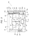
- Fig. 3 is a plan view of the frame holding section 200
- Fig. 4 is a cross-sectional view taken along line A - A in Fig. 3 and illustrating an essential portion.
- a front slider 202 and a rear slider 203 for holding an eyeglass frame are slidably placed on a pair of guide rails 204 and 205 arranged on the right- and left-hand sides of a holding section base 201.
- Pulleys 207 and 208 are rotatably attached respectively to a front-side block 206a and a rear-side block 206b that support the guide rail 204.
- An endless wire 209 is suspended on the pulleys 207 and 208.
- An upper side of the wire 209 is secured to a pin 210 attached to a right end member 203R extending from the rear slider 203, while a lower side of the wire 209 is secured to a pin 211 attached to a right end member 202R extending from the front slider 202.
- the frame is clamped by clamp pins 230 arranged at total four locations, i.e. by clamp pins 230 at right and left two locations of the front slider 202 and clamp pins 230 at right and left locations of the rear slider 203, so as to be held in a reference plane for measurement.
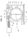
- the geared portion 250a of the rotating base 250 meshes with an idle gear 252, and the idle gear 252 meshes with a gear 253 attached to a rotating shaft of a pulse motor 254 secured to the lower side of the transversely movable base 241.
- a pulse motor 254 secured to the lower side of the transversely movable base 241.
- a feeler unit 255 is attached to the underside of the rotating base 250.
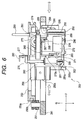
- a gear 257a attached to a rotating shaft of the motor 257 meshes with a rack 262 fixed to a lower portion of the transversely movable supporting base 260, and the transversely movable supporting base 260 is moved in the left-and-right direction (in the arrow F direction) in Fig. 6 by the rotation of the motor 257. Further, the rotation of the gear 257a attached to the rotating shaft of the motor 257 is transmitted to the encoder 258 through an idle gear 259, and the amount of movement of the transversely movable supporting base 260 is detected from this amount of rotation.
- a vertically movable supporting base 265 is supported by the transversely movable supporting base 260 to be movable in the vertical direction (in the arrow G direction).
- a slide rail (not shown) attached to the vertically movable supporting base 265 is slidably held on a guide rail receiver 266 attached to the transversely movable supporting base 260 and extending in the vertical direction.
- a vertically extending rack 268 is secured to the vertically movable supporting base 265, a gear 270a of a DC motor 270 attached to the transversely movable supporting base 260 by means of a fixing metal plate meshes with the rack 268, and as the motor 270 rotates, the vertically movable supporting base 265 is moved vertically. Further, the rotation of the motor 270 is transmitted through an idle gear 271 to an encoder 272 attached to the transversely movable supporting base 260 by means of a fixing metal plate, and the encoder 272 detects the amount of movement of the vertically movable supporting base 265. Incidentally, a downward load of the vertically movable supporting base 265 is reduced by a power spring 275 attached to the transversely movable supporting base 260, thereby rendering the vertical movement of the vertically movable supporting base 265 smooth.
- a limiting member 281 is attached to a lower end of the shaft 276.
- This limiting member 281 has a substantially hollow cylindrical shape, and a protrusion 281a is formed on its side surface along the vertical direction (the arrow G direction), while another protrusion 281a is formed on the opposite side opposite with respect to the paper surface of Fig. 6.
- these two protrusions 281a respectively abut against notched surfaces 265a (the illustrated notched surface 265a, and a similar notched surface 265a that is provided on the opposite side with respect to the paper surface of Fig. 6) formed in the vertically movable supporting base 265, the rotation of the shaft 276 (i.e., the rotation of the feeler 280) is limited to a certain range.
- An obliquely cut slanting surface is formed on a lower portion of the limiting member 281.
- this slanting surface abuts against a slanting surface of a block 263 secured to the transversely movable supporting base 260.
- the rotation of the limiting member 281 is guided to the state shown in Fig. 6, thereby correcting the orientation of the tip of the feeler 280.
- a measuring pin i.e. a template measuring feeler, 290 is vertically slidably held on a right-hand side portion of the transversely movable supporting base 260.
- a mechanism for vertically moving the measuring pin 290 a mechanism is conceivable in which a motor is attached to the transversely movable supporting base 260, and the measuring pin 290 is vertically moved by such as a mechanism including a rack and a pinion.
- the motor, the rack, the pinion, and the like are merely attached to the transversely movable supporting base 260 adds weight of these components, an inertial force becomes large when the transversely movable supporting base 260 is moved.
- a pin moving supporting base 291 is attached to a lower end of the measuring pin 290 which is vertically slidably held on the transversely movable supporting base 260.
- a plate 292 extending in a direction perpendicular to the plane of the drawing of Fig. 6 is attached to a lower end of the transversely movable supporting base 260.
- a spring 293 is stretched between this plate 292 and a lower portion of the pin moving supporting base 291, so that the measuring pin 290 is constantly urged in the downward direction.
- photosensors 286 and 287 are attached to the transversely movable supporting base 260 on upper and lower sides thereof, respectively, and as a light shielding plate 285 enters the photosensor 286 or 287, it can be detected whether the measuring pin 290 is at the measuring position (at the position where the measuring pin 290 is at the most elevated position) or at the retreated position (at the most lowered position). In addition, only the photosensor 287 maybe used so as to only detect whether or not the measuring pin 290 is at the measuring position.
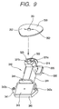
- a hole 331 for inserting a basal part 361 of a cup 360 with a dummy lens fixed thereon is formed in the cup holding portion 330, and a projection 332 for fitting to a key groove 362 formed in the basal part 361 is formed inside the hole 331.
- a sliding member 327 is fixed to the movable shaft 312 inserted in the main body block 311, and its front-side end face 327a is circular-arc shaped (a circular arc of the same diameter as that of the hole 331).
- the template 350 is positioned such that a central hole 351 is fitted over the movable pin 323 while two small holes 352 provided on both sides of the central hole 351 are engaged with the pins 321a and 321b. Subsequently, if the button 314 pushed in toward the main body block 311 side is released, the movable pin 323 is returned in the direction of arrow E by the urging force of the spring 313, and its recessed portion 324 abuts against the wall of the central hole 351 in the template 350, thereby fixing the template 350.
- a fitting portion 340 for fitting the template holder 310 to the attaching plate 300 of the holding section base 201 is provided on the rear side of the main body block 311, and its obverse side (the template holding portion 320 side is assumed to be the obverse side) has the same configuration as the reverse side.
- Pins 342a, 342b and 346a, 346b for insertion into the two holes 302 formed in the upper surface of the attaching plate 300 are respectively implanted on the obverse surface 341 and the reverse surface 345 of the fitting portion 340.
- iron plates 343 and 347 are respectively embedded in the obverse surface 341 and the reverse surface 345.
- Flanges 344 and 348 are respectively formed on the obverse surface 341 and the reverse surface 345 of the fitting portion 340.
- a description will be given of a lens chuck mechanism and a lens rotating mechanism as well as an X-axis moving mechanism and a Y-axis moving mechanism of the carriage 701 by assuming that the direction in which the carriage 701 is moved in parallel to the abrasive-wheel rotating shaft 601 is the X axis, and the direction for changing the axis-to-axis distance between the chuck shafts (702L, 702R) and the abrasive-wheel rotating shaft 601 by the rotation of the carriage 701 is the Y axis.
- a right trace switch 413 on the switch panel section 410 is pressed, whereas in a case where the template 350 is for the left use, a left trace switch 411 is pressed.
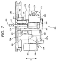
- control unit 150 upon receiving a tracing start signal, drives the motor 283, the gear 297 in mesh with the gear 284 attached to the shaft of the motor 283 rotates, which in turn causes the arm 295 secured coaxially to the gear 297 through the shaft 294 to rotate in the direction of arrow H.
- the pin moving supporting base 291 As the arm 295 rotates in the direction of arrow H, the pin moving supporting base 291 is raised, so that the measuring pin 290 secured to the pin moving supporting base 291 is also raised.
- the light shielding plate 285 attached to the pin moving supporting base 291 enters the photosensor 287, so that the photosensor 287 detects that the measuring pin 290 has risen to the measuring position.
- the measurement of the template 350 is effected in the state in which the measuring pin 290 is separated from the vertically moving mechanism including the motor 283 and the like, and the measuring pin 290 is placed at the measuring position.
- the driving current to the motor 257 is controlled to provide a predetermined driving torque.
- the pulse motor 254 is rotated in accordance with each predetermined unit number of rotational pulses to rotate the feeler unit 255.
- the pin moving supporting base 291 and the measuring pin 290 are moved downward by the slight rotation of the arm 295 in the direction of arrow I with the motor 283 and by the urging force of the spring 293.
- the light shielding plate 285 attached to the pin moving supporting base 291 enters the photosensor 286, thereby detecting the fact that the measuring pin 290 has been lowered to the lower position (retreated position).
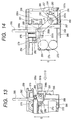
- Fig. 13 is a side elevational view for explaining the modification of the feeler unit 255
- Fig. 14 is a view taken in the direction of arrow D in Fig. 13.
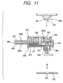
- the construction shown in Fig. 13 differs from the construction shown in Fig. 6 in that the plate 292 and the spring 293 are omitted, and a downward force acts on the pin moving supporting base 291 due to its own weight.
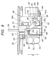
- the construction shown in Fig. 14 differs from the construction shown in Fig. 8 in that a pin 291b is provided on the pin moving supporting base 291 instead of the slot 291a, and the arm 295 is provided with pins 296a and 296b on its upper and lower sides, respectively, so that the pin 291b is interposed between the pins 296a and 296b.
- control unit 150 When the control unit 150, upon receiving a tracing start signal, rotates the motor 283, the gear 297 is rotated, which, in turn, rotates the arm 295 in the direction of arrow H. The rotation of the arm 295 in the direction of arrow H causes the pin moving supporting base 291 to be moved upward, so that the measuring pin 290 secured to the pin moving supporting base 291 is also moved upward.
- the control unit 150 drives the motor 257 to move the transversely movable supporting base 260 so that the measuring pin 290 is oriented toward the center (in the direction of arrow D).
- the control unit 150 drives the motor 257 to move the transversely movable supporting base 260 so that the tip of the feeler 280 is inserted into the frame groove of the frame.
- the driving current (driving torque) to the motor 257 can be controlled to provide a predetermined driving torque. Therefore, it is possible to impart a weak pressing force of such a degree that the frame in not deformed and that the feeler 280 is not dislocated.
- the pulse motor 254 is rotated in accordance with each predetermined unit number of rotational pulses to rotate the feeler unit 255 together with the rotating base 250.
- the transversely movable supporting base 260 together with the feeler 280 moves along the direction of the rail of the guide rail receiver 256a (in the direction of arrow F) in accordance with the radius vector of the frame groove, and the amount of its movement is detected by the encoder 258.
- the vertically movable supporting base 265 together with the feeler 280 moves in accordance with the warp (curve) of the frame groove vertically along the direction of the rail of the guide rail receiver 266 (in the direction of arrow G), and the amount of its movement is detected by the encoder 272.
- the lens frame shape is measured from the angle of rotation ⁇ of the pulse motor 254, the amount r detected by the encoder 258, and the amount z detected by the encoder 272.
- the inertial force at the time of movement does not become large. Therefore, the tip of the feeler 280 moves along the frame groove without being dislocated from the frame groove, and the target lens shape of the lens frame is measured with high accuracy.
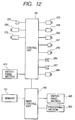
- the operator Upon completion of the measurement of the target lens shape in the above-described manner, the operator presses a data switch 421 on the switch panel section 420, so that the target lens shape data is transferred to a data memory 161, and the target lens shape is graphically displayed on the display 415.
- the operator By operating switches for data input arranged on the switch panel section 420, the operator enters layout data such as the PD value of the wearer, the frame PD, and positional data on the optical center height. Further, the operator enters data on the processing conditions such as the material of the frame, lens material, and the like. Subsequently, the operator allows the lens LE to be chucked by the chuck shafts 702L and 702R to perform processing.
- a main control unit 160 of the lens processing apparatus executes the lens shape measurement by using the lens-shape measuring section 500 in accordance with a processing sequence program. Subsequently, on the basis of the processing data obtained in accordance with the inputted data, the driving of the respective motors of the lens processing section 800 is controlled to move the carriage 701 transversely (in the X direction) and vertically (in the Y direction), and bring the lens LE into pressure contact with a rotating abrasive wheel of a group of abrasive wheels 602 for processing.
Landscapes
- Engineering & Computer Science (AREA)
- Mechanical Engineering (AREA)
- Chemical & Material Sciences (AREA)
- Ceramic Engineering (AREA)
- Inorganic Chemistry (AREA)
- Grinding And Polishing Of Tertiary Curved Surfaces And Surfaces With Complex Shapes (AREA)
- Eyeglasses (AREA)
- A Measuring Device Byusing Mechanical Method (AREA)
- Length Measuring Devices With Unspecified Measuring Means (AREA)
Abstract
Description
wherein the template is measured using a space that is defined when the sliders are located away from each other at a predetermined distance against an urging force of the urging means.
wherein the sliders are fixed to have the predetermined distance therebetween when the template is fixed at the position by the fixing means.
wherein the first moving means and the third moving means have a common moving mechanism.
Claims (9)
- A target lens shape measuring device for measuring a target lens shape of an eyeglass lens, comprising:a template feeler contactable with a periphery of a template;first moving means for moving the template feeler in a radius vector direction of the template along a guide;template measuring means for detecting movement of the template feeler, and obtaining radius vector information of the template based on a result of detection thereof;second moving means for moving the template feeler between a measuring position and a retracted position, the second moving means including a driving power source and a transmitting mechanism for transmitting power of the driving power source, wherein the transmitting mechanism moves the template feeler from one of the measuring position and the retracted position to the other of the measuring position and the retracted position in a state in which the transmitting mechanism is engaged with a member of the first moving means, and the transmitting mechanism is disengaged from the member of the first moving means upon the template feeler reaches the measuring position; anddetecting means for detecting a state in which the template feeler is located at the measuring position.
- The device according to claim 1, further comprising:control means for operating the first moving means to measure the template based on a result of detection by the detecting means.
- The device according to claim 1, further comprising:fixing means for fixing the template at a predetermined position.
- The device according to claim 1, further comprising:an eyeglass frame holding unit including a pair of sliders contactable respectively with an upper end surface and a lower end surface of an eyeglass frame, clamp pins provided on the sliders and adapted to clamp the eyeglass frame, and urging means for urging the sliders toward each other,
wherein the template is measured using a space that is defined when the sliders are located away from each other at a predetermined distance against an urging force of the urging means. - The device according to claim 4, further comprising:fixing means for fixing the template at a predetermined position,
wherein the sliders are fixed to have the predetermined distance therebetween when the template is fixed at the position by the fixing means. - The device according to claim 4, further comprising:slider detecting means for detecting whether or not the sliders are located to have the predetermined distance therebetween; andmode detecting means for detecting, based on a result of detection by the slider detecting means, a template measuring mode in which the template is to be measured.
- The device according to claim 1, further comprising:a frame feeler contactable with a frame groove of a lens frame of an eyeglass frame;third moving means for moving the frame feeler in a radius vector direction of the lens frame; andframe measuring means for detecting movement of the frame feeler, and obtaining radius vector information of the lens frame based on a result of detection thereof;
wherein the first moving means and the third moving means have a common moving mechanism. - The device according to claim 7, wherein the template measuring means and the frame measuring means have a common movement detecting mechanism.
- An eyeglass lens processing apparatus, provided with the target lens shape measuring device of claim 1, for processing the eyeglass lens based on the obtained target lens shape, the apparatus comprising:lens processing means having a rotatable abrasive wheel and a lens rotating shaft adapted to hold and rotate the lens; andprocessing control means for controlling the lens processing means based on the obtained target lens shape.
Applications Claiming Priority (2)
| Application Number | Priority Date | Filing Date | Title |
|---|---|---|---|
| JP22008999A JP3734386B2 (en) | 1999-08-03 | 1999-08-03 | Ball shape measuring device |
| JP22008999 | 1999-08-03 |
Publications (3)
| Publication Number | Publication Date |
|---|---|
| EP1074340A2 true EP1074340A2 (en) | 2001-02-07 |
| EP1074340A3 EP1074340A3 (en) | 2003-07-09 |
| EP1074340B1 EP1074340B1 (en) | 2008-12-17 |
Family
ID=16745764
Family Applications (1)
| Application Number | Title | Priority Date | Filing Date |
|---|---|---|---|
| EP00116520A Expired - Lifetime EP1074340B1 (en) | 1999-08-03 | 2000-07-31 | Target-lens-shape measuring device and eyeglass-lens processing apparatus having the same |
Country Status (5)
| Country | Link |
|---|---|
| US (1) | US6530156B1 (en) |
| EP (1) | EP1074340B1 (en) |
| JP (1) | JP3734386B2 (en) |
| DE (1) | DE60041106D1 (en) |
| ES (1) | ES2319720T3 (en) |
Cited By (1)
| Publication number | Priority date | Publication date | Assignee | Title |
|---|---|---|---|---|
| CN111958393A (en) * | 2020-08-17 | 2020-11-20 | 何福生 | Quick molding equipment that polishes of hyperopia glasses substrate |
Families Citing this family (9)
| Publication number | Priority date | Publication date | Assignee | Title |
|---|---|---|---|---|
| JP3916445B2 (en) * | 2001-11-08 | 2007-05-16 | 株式会社ニデック | Eyeglass lens processing equipment |
| JP4267228B2 (en) * | 2001-12-03 | 2009-05-27 | 株式会社トプコン | Lens frame shape measuring device |
| JP5204527B2 (en) * | 2008-03-28 | 2013-06-05 | 株式会社トプコン | Ball shape measuring device |
| JP5435918B2 (en) * | 2008-09-30 | 2014-03-05 | 株式会社トプコン | Target lens shape measuring method and apparatus |
| JP5562624B2 (en) * | 2009-12-09 | 2014-07-30 | 株式会社ニデック | Eyeglass frame shape measuring device |
| US8860931B2 (en) * | 2012-02-24 | 2014-10-14 | Mitutoyo Corporation | Chromatic range sensor including measurement reliability characterization |
| US8928874B2 (en) | 2012-02-24 | 2015-01-06 | Mitutoyo Corporation | Method for identifying abnormal spectral profiles measured by a chromatic confocal range sensor |
| CN102853748A (en) * | 2012-08-29 | 2013-01-02 | 江苏太平洋精锻科技股份有限公司 | Spherical measuring device of planet bevel gear |
| CN108788989A (en) * | 2018-09-03 | 2018-11-13 | 上海光和光学制造大丰有限公司 | A kind of glass grinding device on vehicle mounted guidance |
Family Cites Families (16)
| Publication number | Priority date | Publication date | Assignee | Title |
|---|---|---|---|---|
| DE3578898D1 (en) * | 1984-12-25 | 1990-08-30 | Topcon Corp | DEVICE FOR MEASURING THE PROFILE OF GLASSES. |
| JP2761590B2 (en) | 1989-02-07 | 1998-06-04 | 株式会社ニデック | Eyeglass lens grinding machine |
| JP2845945B2 (en) | 1989-06-07 | 1999-01-13 | 株式会社日立製作所 | Magnetron |
| FR2652893B1 (en) * | 1989-10-06 | 1993-03-19 | Essilor Int | CONTOUR READING APPARATUS, PARTICULARLY FOR GLASSES. |
| JP2925685B2 (en) | 1990-08-02 | 1999-07-28 | 株式会社ニデック | Frame shape measuring device |
| US5333412A (en) * | 1990-08-09 | 1994-08-02 | Nidek Co., Ltd. | Apparatus for and method of obtaining processing information for fitting lenses in eyeglasses frame and eyeglasses grinding machine |
| JP2918657B2 (en) | 1990-08-09 | 1999-07-12 | 株式会社ニデック | Eyeglass lens grinding machine |
| JP2907974B2 (en) | 1990-08-28 | 1999-06-21 | 株式会社ニデック | Eyeglass frame tracing device |
| JP3011526B2 (en) | 1992-02-04 | 2000-02-21 | 株式会社ニデック | Lens peripheral processing machine and lens peripheral processing method |
| JPH0799329B2 (en) * | 1993-06-24 | 1995-10-25 | 株式会社トプコン | Eyeglass lens frame or template shape measuring device |
| FR2751433B1 (en) * | 1996-07-18 | 1998-10-09 | Essilor Int | PROCESS FOR TAKING UP THE CROWNING SECTION OF A GLASSES FRAME, CORRESPONDING SENSOR, AND APPLICATION OF THIS PROCESS TO OVERFLOWING THE MOUNTING GLASS |
| US5959199A (en) | 1996-11-22 | 1999-09-28 | Kabushiki Kaisha Topcon | Apparatus for measuring the contour of a lens-shaped template formed to be fit in a lens frame of an eyeglass frame |
| US6006592A (en) | 1996-11-22 | 1999-12-28 | Kabushiki Kaisha Topcon | Apparatus for measuring the contour of a lens-shaped template formed to be fit in a lens frame of an eyeglass frame |
| JP3929568B2 (en) | 1996-11-29 | 2007-06-13 | 株式会社トプコン | Eyeglass shape measuring device for eyeglass frames |
| JP4068177B2 (en) | 1997-03-31 | 2008-03-26 | 株式会社ニデック | Lens grinding machine |
| JP3989593B2 (en) * | 1997-05-26 | 2007-10-10 | 株式会社トプコン | Eyeglass shape measuring device for eyeglass frames |
-
1999
- 1999-08-03 JP JP22008999A patent/JP3734386B2/en not_active Expired - Fee Related
-
2000
- 2000-07-31 ES ES00116520T patent/ES2319720T3/en not_active Expired - Lifetime
- 2000-07-31 EP EP00116520A patent/EP1074340B1/en not_active Expired - Lifetime
- 2000-07-31 DE DE60041106T patent/DE60041106D1/en not_active Expired - Lifetime
- 2000-08-03 US US09/631,962 patent/US6530156B1/en not_active Expired - Fee Related
Cited By (1)
| Publication number | Priority date | Publication date | Assignee | Title |
|---|---|---|---|---|
| CN111958393A (en) * | 2020-08-17 | 2020-11-20 | 何福生 | Quick molding equipment that polishes of hyperopia glasses substrate |
Also Published As
| Publication number | Publication date |
|---|---|
| US6530156B1 (en) | 2003-03-11 |
| ES2319720T3 (en) | 2009-05-12 |
| DE60041106D1 (en) | 2009-01-29 |
| JP2001041734A (en) | 2001-02-16 |
| JP3734386B2 (en) | 2006-01-11 |
| EP1074340A3 (en) | 2003-07-09 |
| EP1074340B1 (en) | 2008-12-17 |
Similar Documents
| Publication | Publication Date | Title |
|---|---|---|
| US6325700B1 (en) | Eyeglass-frame-shape measuring device and eyeglass-lens processing apparatus having the same | |
| EP1050372B1 (en) | Eyeglass-lens processing apparatus | |
| USRE35898E (en) | Lens periphery processing apparatus, method for obtaining processing data, and lens periphery processing method | |
| EP1090716A2 (en) | Target-lens-shape measuring device, and eyeglass-lens processing apparatus having the same | |
| US6350190B1 (en) | Template holder, target lens shape measuring device having the holder, and eyeglass lens processing apparatus having the device | |
| US5959199A (en) | Apparatus for measuring the contour of a lens-shaped template formed to be fit in a lens frame of an eyeglass frame | |
| US6241577B1 (en) | Lens grinding apparatus and lens grinding method and component therefor | |
| US6719609B2 (en) | Eyeglass lens processing apparatus | |
| EP1074340B1 (en) | Target-lens-shape measuring device and eyeglass-lens processing apparatus having the same | |
| US6871158B2 (en) | Apparatus for measuring shape of lens-frames | |
| US6006592A (en) | Apparatus for measuring the contour of a lens-shaped template formed to be fit in a lens frame of an eyeglass frame | |
| EP0881037B1 (en) | Spectacle lens shape measuring apparatus | |
| JP5356082B2 (en) | Eyeglass lens processing equipment | |
| EP1060834B1 (en) | Lens measuring device | |
| JP3778726B2 (en) | Template holder | |
| JPH06194153A (en) | Shape measuring device for ophthalmic lens | |
| JP2512940Y2 (en) | Frame shape measuring device | |
| JP2005238378A (en) | Processing method for eyeglass lenses | |
| JPH07112355A (en) | Shape measuring device for rimless glasses |
Legal Events
| Date | Code | Title | Description |
|---|---|---|---|
| PUAI | Public reference made under article 153(3) epc to a published international application that has entered the european phase |
Free format text: ORIGINAL CODE: 0009012 |
|
| AK | Designated contracting states |
Kind code of ref document: A2 Designated state(s): AT BE CH CY DE DK ES FI FR GB GR IE IT LI LU MC NL PT SE |
|
| AX | Request for extension of the european patent |
Free format text: AL;LT;LV;MK;RO;SI |
|
| PUAL | Search report despatched |
Free format text: ORIGINAL CODE: 0009013 |
|
| AK | Designated contracting states |
Designated state(s): AT BE CH CY DE DK ES FI FR GB GR IE IT LI LU MC NL PT SE |
|
| AX | Request for extension of the european patent |
Extension state: AL LT LV MK RO SI |
|
| 17P | Request for examination filed |
Effective date: 20031120 |
|
| AKX | Designation fees paid |
Designated state(s): DE ES FR GB |
|
| 17Q | First examination report despatched |
Effective date: 20060801 |
|
| 17Q | First examination report despatched |
Effective date: 20060801 |
|
| GRAP | Despatch of communication of intention to grant a patent |
Free format text: ORIGINAL CODE: EPIDOSNIGR1 |
|
| GRAS | Grant fee paid |
Free format text: ORIGINAL CODE: EPIDOSNIGR3 |
|
| GRAA | (expected) grant |
Free format text: ORIGINAL CODE: 0009210 |
|
| AK | Designated contracting states |
Kind code of ref document: B1 Designated state(s): DE ES FR GB |
|
| REG | Reference to a national code |
Ref country code: GB Ref legal event code: FG4D |
|
| REF | Corresponds to: |
Ref document number: 60041106 Country of ref document: DE Date of ref document: 20090129 Kind code of ref document: P |
|
| REG | Reference to a national code |
Ref country code: ES Ref legal event code: FG2A Ref document number: 2319720 Country of ref document: ES Kind code of ref document: T3 |
|
| PLBE | No opposition filed within time limit |
Free format text: ORIGINAL CODE: 0009261 |
|
| STAA | Information on the status of an ep patent application or granted ep patent |
Free format text: STATUS: NO OPPOSITION FILED WITHIN TIME LIMIT |
|
| 26N | No opposition filed |
Effective date: 20090918 |
|
| PGFP | Annual fee paid to national office [announced via postgrant information from national office to epo] |
Ref country code: DE Payment date: 20130724 Year of fee payment: 14 Ref country code: ES Payment date: 20130628 Year of fee payment: 14 |
|
| PGFP | Annual fee paid to national office [announced via postgrant information from national office to epo] |
Ref country code: GB Payment date: 20130731 Year of fee payment: 14 Ref country code: FR Payment date: 20130724 Year of fee payment: 14 |
|
| REG | Reference to a national code |
Ref country code: DE Ref legal event code: R119 Ref document number: 60041106 Country of ref document: DE |
|
| GBPC | Gb: european patent ceased through non-payment of renewal fee |
Effective date: 20140731 |
|
| REG | Reference to a national code |
Ref country code: FR Ref legal event code: ST Effective date: 20150331 |
|
| PG25 | Lapsed in a contracting state [announced via postgrant information from national office to epo] |
Ref country code: DE Free format text: LAPSE BECAUSE OF NON-PAYMENT OF DUE FEES Effective date: 20150203 |
|
| REG | Reference to a national code |
Ref country code: DE Ref legal event code: R119 Ref document number: 60041106 Country of ref document: DE Effective date: 20150203 |
|
| PG25 | Lapsed in a contracting state [announced via postgrant information from national office to epo] |
Ref country code: GB Free format text: LAPSE BECAUSE OF NON-PAYMENT OF DUE FEES Effective date: 20140731 Ref country code: FR Free format text: LAPSE BECAUSE OF NON-PAYMENT OF DUE FEES Effective date: 20140731 |
|
| REG | Reference to a national code |
Ref country code: ES Ref legal event code: FD2A Effective date: 20150827 |
|
| PG25 | Lapsed in a contracting state [announced via postgrant information from national office to epo] |
Ref country code: ES Free format text: LAPSE BECAUSE OF NON-PAYMENT OF DUE FEES Effective date: 20140801 |